
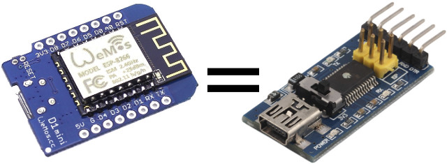
USB to serial boards are necessary to program and debug boards, and/or access the serial console, and while they are very cheap, you may be in a situation where you don’t have any around, but you do have some Arduino compatible boards. It’s been possible to transform an Arduino board into a USB to TTL debug for several years using ArduinoSerialBypass.ino sketch, but I’ve been informed this also works on ESP8266 boards such as Wemos D1 Mini.
 The sketch could not be simpler:
|
1 2 3 4 5 6 7 8 9 |
void setup() { pinMode(0,INPUT); pinMode(1,INPUT); } void loop() { } |
The code simply makes sure that Tx and Rx pins are set as inputs in order not to disturb the serial connection as explained below:
This code makes the Arduino not interfere with pins 0 and 1 which are connected to RX and TX on the FTDI chip. This allows the data coming from the FTDI USB 2 Serial chip to flow directly to another device. Since RX and TX are labeled from the Arduino’s point of view, don’t cross the wires, but plug the device’s RX wire into the RX pin 0 and the TX wire into the TX pin 0
This should work with any Arduino compatible boards with a USB to serial chip, but it’s nice that it has been confirmed to work on Wemos D1 mini. If you’d rather get a WiFi to serial bridge, that’s what ESPLink firmware is for.
Thanks to Zoobab for the tip.

Jean-Luc started CNX Software in 2010 as a part-time endeavor, before quitting his job as a software engineering manager, and starting to write daily news, and reviews full time later in 2011.
Support CNX Software! Donate via cryptocurrencies, become a Patron on Patreon, or purchase goods on Amazon or Aliexpress


Is there any complete tutorial for ESP noobs?
@Peter
You need to install the Arduino firmware to the board, and load the Arduino IDE on your computer, then create a sketch with the code above, and load it to the board. You should be able to adapt the instructions @ http://www.cnx-software.com/2016/03/22/getting-started-with-wemos-d1-mini-esp8266-board-dht-relay-shields/
Finally, you connect the board via USB to your computer, and connect the Tx, Rx, and GND pins between the ESP8266 board and your target board. Connect with your prefer software (minicom, screen, putty…) and serial settings, and you should be good to go.
I think I’m missing something here: Load the Arduino IDE on your computer Connect the board via USB to your computer and select the basic board/port settings for your board in the IDE so it can communicate with the board. Create a sketch with the code above and load it to the board. Disconnect the board from USB? With both boards unplugged from power/USB, connect the Tx, Rx, and GND pins between the ESP8266 board and your target board. Reconnect USB to the board you’re using as a passthrough. Connect with your prefer software (minicom, screen, putty…) and serial settings,… Read more »
Usually, the serial debug board (ESP8266 here) gets its power from the USB port on the computer, but the target board may also need its own power, although sometimes it can be powered by the 5V/GND from the serial debug board.
Seems I misunderstood: I though this is serial to wifi adapter. I’m thinking to build one with spare NanoPi NEO I have.
@Peter
For serial to WiFi check the ESPLink link at the end of the post. It will do what you want.
@Jean-Luc Aufranc (CNXSoft) Perfect! This is exactly what I’m looking for.
And sorry all for spamming thread 🙁
Beware some Arduinos are normally running at 5V, so the usb-serial converter will run at 5V as well.
Years ago I hacked a USB cable to feed the power of the USB into the external connector, so that the whole board would run at 3.3V:
http://www.zoobab.com/arduino-duemilanove-in-3-3v
This hack only works for the Duemilanove, which has 2 voltage regulators cascaded.
The ESP runs at 3.3V, so if you have a Wemos or a Witty cloud, the TTL output is at 3.3V.