
When I review media player or development boards, I’m often asked about power consumption figures. One way to measure power consumption is to use a Kill-a-Watt, but for low power devices it’s not always accurate enough, and it also includes the heat dissipation from the power adapter, which may or may not be useful depending on what you want to measure. For USB powered devices or boards, an easy way to measure power consumption is to use CHARGER Doctor, a small $5 USB dongle that displays both voltage and current alternatively. Unfortunately, most products I’ve received lately use barrel type connectors, so this little tool has not been as useful as I hoped. The only solution is then to measure voltage and current with a multimeter. Voltage is measured in parallel, so you just need to point the multimeter’s leads where you want to perform the measurements. However, the current is measure in series, so you need to insert the multimeter in the circuit somehow. A few possibilities:
- Unsoldering a component on the board to place the multimeter in series.
- Cut one wire of the power cable to insert the multimeter.
- Get and make a board to insert the multimeter.
Solutions 1 and 2 are not really desirable, so I decided to look into solution 1, and since I could not find any board that could match my requirements, I decided to work out a solution by myself allowing various power inputs and outputs.
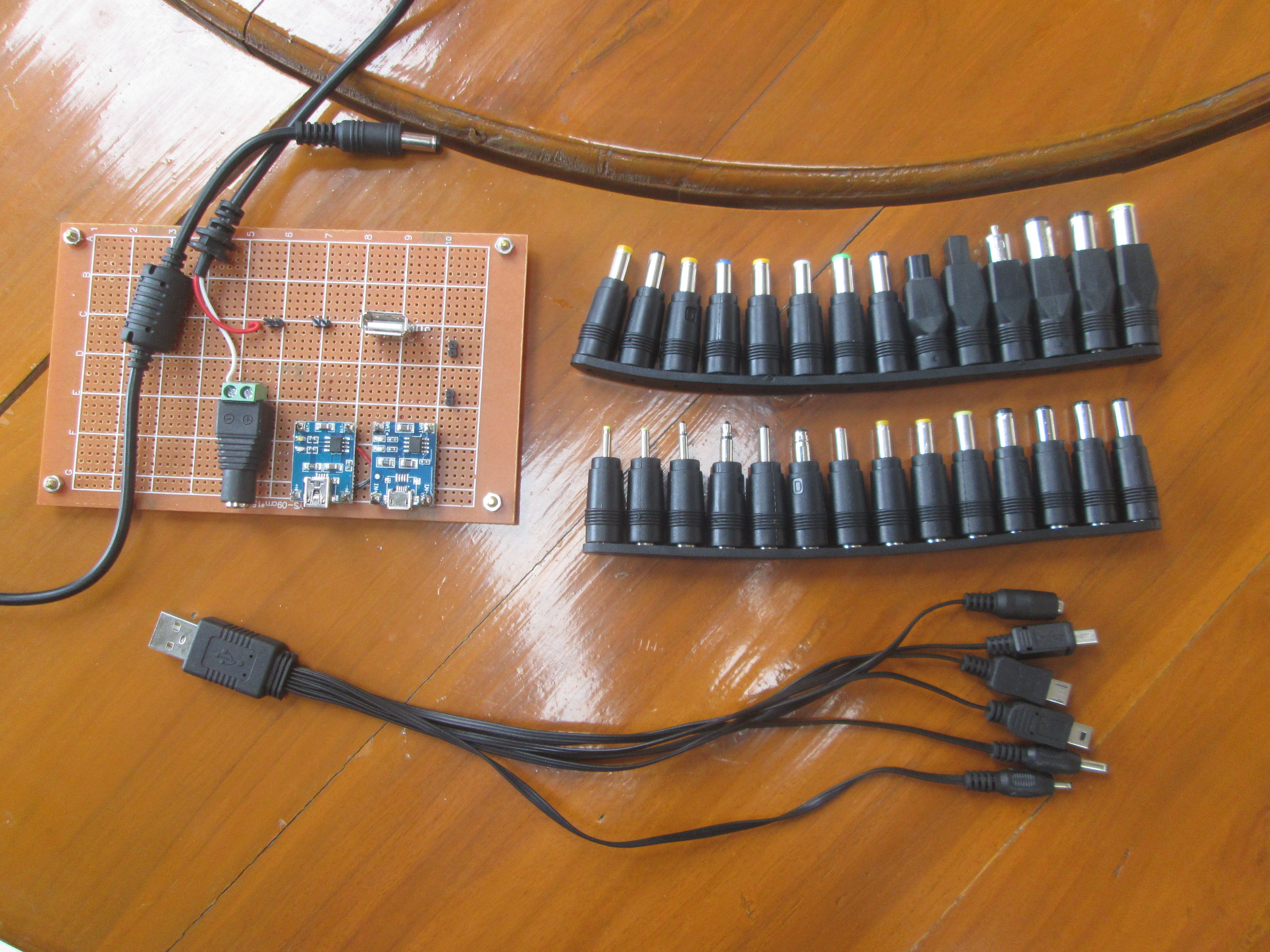
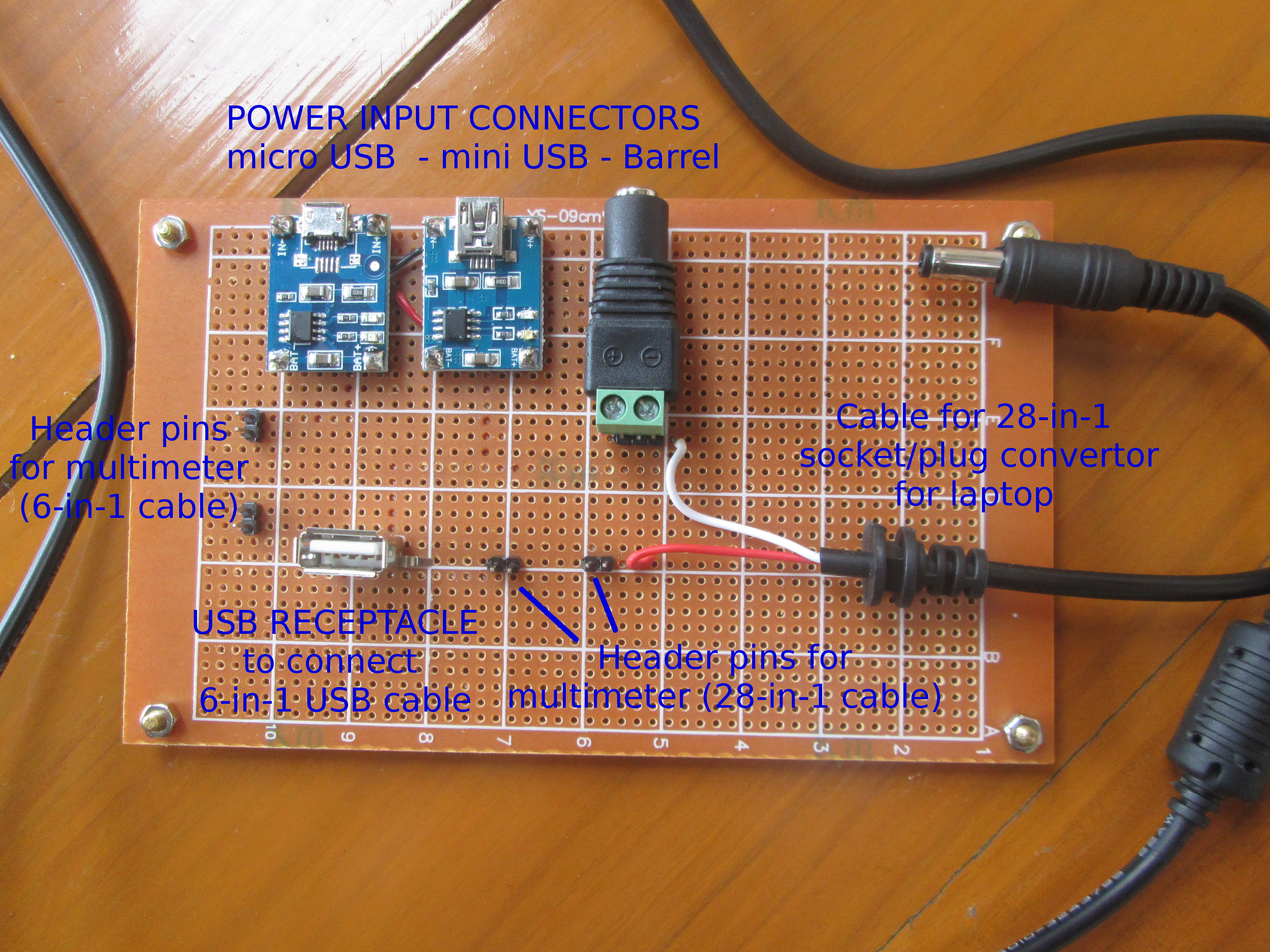
The board can take power adapter using micro USB, mini USB or 5.5/2.1mm barrel connectors, 32 different output connectors thanks to two cables, and header pins are used to connect the multimeter’s leads.
Here’s the different components required for this solution:
- 1x perfboard or veroboard
- Some 2.54mm pin headers (straight and right angle)
- micro USB breakout board – $1.50 on Adafruit, but shipping + insurance was $12, so instead I purchased 5x micro USB charging board for $4.24 on Ebay (asp_ezone)
- mini USB breakout board – $1.95 on Sparkfun, but shipping killed it again, so I purchase 2x mini USB charging boards for $2.75 on asp_ezone shop.
- 5.5/2.1mm DC power socket – $4.18 for 10 pieces
- USB Female DIP Socket Connector – $1.73 for 10 pieces
- 6-in-1 Universal USB charging cable – $3.41
- Universal 28-in-1 DC power socket / plug converter for laptop – $11.30
If you purchase everything from scratch the cost would be around $35.
In case the introduction is not clear, the board description below may help.
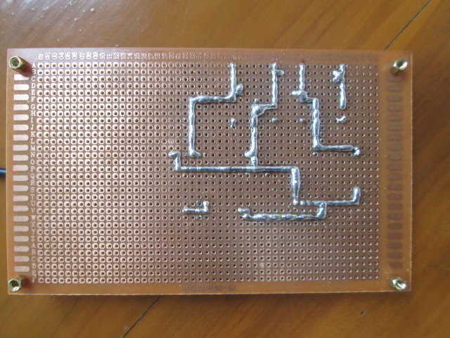
Iv’e also included the back of the board with the soldering for reference.
 After double checking I had not made a mistake inverting GND and VCC, which could be fatal, I tried it out by making some power measurements with Tronsmart Vega S89 Elite.
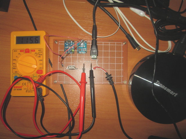 In power off mode, I get 115 mA (~ 575 mW @ 5V), so I’m confident it’s working just fine… Unfortunately, I quickly realized something is wrong as the boot does not complete most of the time, as it reaches 1A, the boot just simply stops, or I just get a blue screen. Only once or twice did I managed to get to the home screen (about 0.52A after most background tasks are done), but starting an app will hang the system most of the time. So I’ve tried to replace the multimeter by a breadboard female to female cable, and everything works normally. So I suspect the contact surface with the leads is not large enough, or the multimeter introduces some noise that disturbs the device…. I’ll get some crocodile clips to see if things work out better…

Jean-Luc started CNX Software in 2010 as a part-time endeavor, before quitting his job as a software engineering manager, and starting to write daily news, and reviews full time later in 2011.
Support CNX Software! Donate via cryptocurrencies, become a Patron on Patreon, or purchase goods on Amazon or Aliexpress


I see you’ve got a multiheaded USB to male barrel adapter. Wouldn’t a female barrel to USB adapter let you use the ‘Charger Doctor’?
Ah, good ol’ low impedance of some el-cheapo multimeter, simplest try to see is it the low impedance prob, simply use the high ampere measurement connector on the multimeter (commonly 10A range, instead of 1A range, can’t see your multimeter labels).
You might also consider getting the simple to use uCurrent (microCurrent) adapter from EEVBlog guy from down under. 🙂
@onebir
I could use the Charger Doctor via the USB female connector, It would work but only for 5V power supply. 9V and 12V powered adapter which are still relatively common would not work. I’d also need another “USB to barrels” cable.
Not sure how I would use a female barrel to USB adapter with Charger Doctor and this setup.
@anon
I’m using 200 mA range in the pic above, that’s the max supported in the standard range, and I only used it in power off mode. Before I booted the device I had already switched to 10A, since such devices will usually .
I’ve checked uCurrent (http://www.eevblog.com/projects/ucurrent/), it looks like it’s to improve accuracy when measuring very low current (nanoamp…). It’s quite possible I do not clearly understand what it is for…
I might need a better multimeter… The specifications do not mention anything about the impedance for current measures, just the accuracy. They also mention “In 10A range, measure time cannot exceed 15 seconds”. Not sure why, but this could explain my issue…
Yeah, personally do not have uCurrent, so had to check the ampere range, and it is good only for 1.25A… The idea of it is tyo convert Amperes to Voltages, so you would use normal voltage meter, instead of Ampere meter, that messes up with impedance (burden voltage = voltage drop).
Quick’n’dirty explanation of “impedance” is that it is almost exactly what resistance is (but varies per voltage), high impedance = high resistance = bigger drop in series voltage = lower currencies possible to measure, low impedance = low resistance = lower drop in series voltage = higher currency measure (why I talked about the 10A plug, instead of 1A plug).
Obviously your multimeter is somewhat crusty… Real way would to do a shunt resistor (uber low impedance) with an opamp… But that starts to be somewhat too involving for such simple currency measurements, the Net likely has such circuits already been made for cheap (SeeedStudio/SparkFun/AdaFruit and alike).
Anywho the Net is full of reference/educational documentation about it… Good luck, took awhile myself to get the idea when I was in EE school way back when. 😉
@anon
Electronic Engineering degree here, although I have not used it much.
What I meant is that they did not mention the impedance value in the specs.
For my DIYs, I use a WM-010 watt meter, with your same solution (multiple jacks in and out) for the devices.
With the external temperature sensor, I check the heating of the chips of the board (devices under test)…to decide heatsink or not.
http://www.hobbyhot.com/SKYRC-RC-Model-WM-010-High-Precision-Battery-Watt-Meter-BK210.html
To control the amount of power used by the power adapter + devices, I use a PZEM-002, DIYed into a box with socket for 220Vac + fuse + switch for each line of output.
http://www.aliexpress.com/item/AC-Digital-LED-Power-Meter-Monitor-Voltage-KWh-Time-Watt-Energy-Volt-Ammeter-5pcs-lot/1784207995.html
So I’ve given it another try with UNI-T UT61E multimeter (http://www.cnx-software.com/2014/10/19/50-uni-t-ut61e-digital-multimeter-supports-data-logging-to-a-windows-computer/)
At first I had the same problem, but with anything over 400 mA failing. I used cable with crocodile clip for a better connection, but then I measured the impedance of the cables: 0.90 Ohm… So even if I remove the multimeter, and simply use these cables, the board won’t boot.
I measured my two pair of test leads:
Pair 1 – 0.30 Ohm
pair 2 – 0.13 Ohm
Pair 2 works OK, and I can boot, but the TV will often blink, and the device will reboot in benchmarks when I see the current jump to 2A or so. I’m using a 5V/8A SMPS power supply.
So the key for current measurement is the impedance of the multimeter and test leads.
Maybe I should use some shunt resistance instead..