
Yesterday one person contacted me on Facebook asking me whether there was any chance of me doing a “which usd-micro usb cable is best”, as there’s not much clear information on the Internet. His purpose was to charge his phone, but many development boards come with a micro USB port, and I’ve read many comments about powering the board. It also happened to me, and the main cause can either be the power supply which does not work as rated (usually 5V/2A), or the micro USB cable which may have a resistance a little to high leading to voltage drops. You’ll know you may have a power problem when the board refuses to boot, and usually boot loop, or randomly reboots especially under high load. The first solution is to get a power supply that provide the right voltage and amperage, and you can test that with USB Charger doctor an ultra cheap tool that will show both the voltage and intensity on an LCD display, although it will only work on chargers with a USB port.
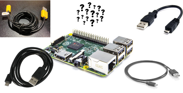 But what about the micro USB cable? Let’s consider the actual problem, which is well explained in a post about USB cable resistance, but I’ll summarize below. First all conductor have some tiny resistance, and usually the thicker the cable the less resistance there is. The American Wire Gauge (AWG) value is often used to describe the thickness of the cable, with numbers from 0 to 40 ranging from the larger diameter/smaller resistance/higher capacity to the smaller diameter/larger resistance/lower capacity. For USB cable, AWG20 to AWG28 are often used for USB cables, and the latter seems to be very common for data wires, but what matters here is the AWG value for the power wires (5V/GND) of the cable. The resistance also depends on the length of the cable with longer cables having a longer resistance, as well as the USB contact resistance, but I’m not sure we can do much about that one. Anyway, that means a short cable with a lower AWG value would be better suited here, as shown in the table below from the aforelinked post using 5V/1A and 5V/1A loads. This table assumes 30 mOhms contact resistance, so the values would be lower if there’s a lower resistance.
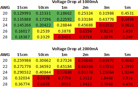
Boards can normally work in a range around 5V. For the sake of argument, let’s assume a board taking 4.5V to 5.5V DC input. and would reboot if the voltage drops below 4.5V. If you have a 5V power supply use with a non-optimal AWG rating and length, the voltage will drop more than 0.5V (red zone above) and the board will not work properly. 5V/1A (5W) is a very common on development boards, while getting to 10Watts is possible for you’d need a high load plus possible some USB storage device to reach the power level.
Based on those results, what we want is an AWG20 cable (ideally) with a length of less than one meter, and the shorter the better. So I’ve been looking for such cables on the web and found a bunch. I did not test any, but they may be good candidates to look at:
- KoPI 20AWG micro USB cable selling for $5.99 on Newegg.
- 5x Tronsmart micro USB cables for $8.49 shipped: 1x 6 feet (not ideal), 3x 3.3 feet (~1 meter), 1x 1 foot (33 cm).
- 35 cm micro USB cable (AWG20) for $2.99 shipped on eBay. It can also be found on Aliexpress for $2.49.
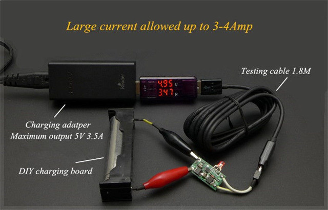
There are many others, just search for AWG20 micro USB cable, or in some cases micro USB charging cables, and you should find decent cables that should not cause power or charging troubles. The last cable in the list above (eBay) was tested with a Charger Doctor dongle showing 4.95V/3.47A going through the cable (1.8 meter length). The voltage value should be lower when measured at the DIY charging board due the internal resistance of the cable, but it still shows the cable allows around 3 to 4 amps.

Jean-Luc started CNX Software in 2010 as a part-time endeavor, before quitting his job as a software engineering manager, and starting to write daily news, and reviews full time later in 2011.
Support CNX Software! Donate via cryptocurrencies, become a Patron on Patreon, or purchase goods on Amazon or Aliexpress


It should be noted that approx 100% of all RPi 2 or 3 users are affected by this problem but simply don’t know since the Raspberry Pi’s ‘firmware’ masquerades the problem and in case under-voltage occurs simply throttles the CPU cores down to prevent freezes/reboots. That’s why people using their RPi PSU and cable with other dev boards that are equipped with the horrible Micro USB connector (Pine64+, Tinkerboard, MiQi and some others) think those SBC would be failing while Raspberries are fine.
It’s simple to test this on Raspberries:
If you have one or more 1 digits on the left you’re affected and most probably also suffer from bad performance without even knowing. I made a script for more convenience: https://github.com/bamarni/pi64/issues/4#issuecomment-292707581
@tkaiser
Now that you talk about this, I’ve read the desktop UI displayed a yellow icon in case of under-voltage in Raspberry Pi board.
While I agree that it’s not ideal, having a board that runs is better than a board that does not run at all. Would other boards be able to handle that, or under voltage detection is just not possible on most other boards?
@cnxsoft
In fact it’s a rainbow now that gets displayed by the VideoCore IV over the HDMI framebuffer if under-voltage is detected. And unlike other boards Raspberries have an own low-voltage detection circuitry that toggles a GPIO pin which then triggers the above. See at the bottom of: https://www.raspberrypi.org/forums/viewtopic.php?f=28&t=155244
Some other SBC have some circuitry to measure DC-IN current and voltage (eg. most Allwinner A10/A20 boards with their AXP209 PMIC) but the majority not. And unfortunately most users of these Micro USB equipped boards are simply not aware of Ohm’s law and that so many stability problems they blame software for are related to PSU and/or USB cable between PSU and board.
What’s even worse: When people run into these issues (freezes, spontaneous reboots) sometimes they fix it later by accident (buying a 10A rated PSU which is pretty useless but just comes with a cable that is not totally crap) but since now their installation/filesystem on SD card or eMMC is already damaged due to the many unsafe shutdowns they now run in software related stability issues and finally throw their boards away or put them in the drawer.
I really don’t understand why RPi folks don’t fix the problem and other vendors still use the crappy connector with new designs. ASUS Tinkerboard for example: everything as expected including the useless recommendation to replace the PSU with another one showing higher amperage ratings: http://tinkerboarding.co.uk/forum/thread-266.html
@tkaiser
The rainbow icon is the old one. THey’ve changed it since it was not really representative.
They now have three icons with under-voltage (yellow lightning bolt), Throttling arm due to temperature (thermometer up a bit), Throttling arm and gpu due to temperature (thermometer full)
https://github.com/raspberrypi/firmware/issues/367#issuecomment-246752301
@cnxsoft
Ah, thanks. I confused it (again). But I still rely on ‘vcgencmd get_throttled’ instead since the bits on the left side indicate that these events happened between now and last boot. So it would be pretty easy to inform every RPi user about insufficient powering or the need to improve heat dissipation to prevent throttling. Just use a shutdown routine in Raspbian that saves the firmware’s answer to the ‘get_throttled’ query and display a warning dialog on next reboot to the user.
@tkaiser when I saw the headline, I thought you would be the first to comment on this 🙂
These are very good tips for cables. One question though, how do SBCs handle max current? Do they pull whatever they want, therefore maybe tripping over-current protections and rebooting the PSU circuit? Or do they look at PSU/charger type?
I’ve been looking at this site for pointers on good PSUs for tablets and phones:
http://lygte-info.dk/info/ChargerIndex%20UK.html
So far I’ve settled on Ravpower PSUs w/ iSmart 2.0, as that applies voltage compensation over load and can handle the rated current without issue.
On my HP Chromebook 11, 24AWG 1m cable can get 4.65-4.8v @ 1.5A, though it doesn’t draw more power due to charger type signaled.
For RPi you probably want 30cm cables or AWG20/22 and it should be able to draw the full 2.4A.
Devices that supply PSUs capable of 3A@5.25v seem to use even thicker, AWG 18, cable with charge only wires. This has very little voltage drop but also needs very sturdy connectors so contact resistance isn’t the main issue.
Isnt the above test setup useless? I mean the voltage is measured before the cable, not after… So not really any value in those (voltage) values.
@itchy n scratchy
That’s mostly testing the power supply, and I mentioned the voltage value was not so useful, for wouldn’t the current be lower if the cable had some higher resistance?
I also like to get USB charning cables with a ON/OFF power-switch on them for dev boards.
https://www.aliexpress.com/item/Raspberry-Pi-3-Power-Cable-with-switch-ON-OFF-button-Micro-USB-charging-cable-for-Banana/32779474605.html
https://www.aliexpress.com/item/Raspberry-Pi-Power-Cable-with-switch-ON-OFF-button-Micro-USB-charging-cable-for-Banana-PI/32685693451.html
That way you can easily power-off the dev boards without pulling out the cable.
@Harley
The switch is good, but those cable are most probably not 20AWG rated based on the price.
One is also 1.5 meter long, so it may cause problems.
There are 20AWG cables with on/off switch, but fairly expensive: http://www.ebay.com/itm/Raspberry-Pi-3-Retropie-OFFICIAL-Power-Supply-ON-OFF-Switch-Cable-Adapter-20AWG-/201857713896
Same with 5V/2.5A power supply: http://www.ebay.com/itm/Raspberry-Pi-3-USB-Power-Supply-5-1V-2-5A-2500mA-20AWG-Switch-microUSB-Cable-/201753550422
@Harley
Do you use those cables with Raspberries? Then you should waste 30 seconds of your life and do the test:
If there are only zeros on the left you’re fine, if not better throw the cables away. I got such a cable with the original Banana Pi over two years ago. Not only the switch on the cable was great to power down the board but also a connected 2.5″ disk trying to spin up. But back at that time I had zero knowledge about Micro USB crappiness and voltage drops 🙂
See also this blog post about fake wire values:
http://nerdralph.blogspot.be/2016/06/when-does-18-26-when-buying-cheap-cables.html
And a nice one about crappy iGadget charging cables: https://youtu.be/VeuiA92fxZI
BTW: One of the reasons why Apple chose to introduce an own proprietary ‘Lightning’ connector standard 5 years ago instead of adopting Micro USB is the same why they also sent truckloads of engineers to USB implementors forum technical commitee responsible for USB-C: since Micro USB is crap and not suitable to charge/power anything with higher current.
And another one showing the power of open minded communities! 🙂
https://forum.armbian.com/index.php?/topic/4767-powering-through-micro-usb/