
After Amlogic S905X based Le Potato board, and the on-going Kickstarter campaign for Tritium Allwinner H2+/H3 boards, Libre Computer has now launched an Indiegogo campaign for their Renegade SBC (Single Board Computer) powered by Rockchip RK3328 SoC.
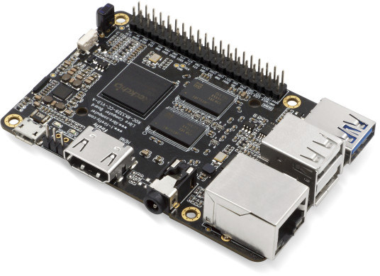
The board follows Raspberry Pi 3 form factor like the two previous models, and three versions of the board are offered with 1, 2 or 4GB RAM, making Renegade SBC a direct competitor to Pine64 ROCK64 board.
 Renegade SBC specifications:
- SoC – Rockchip RK3328 quad core Cortex A53 processor with ARM Mali-450MP2 GPU
- System Memory – 1, 2, or 4 GB DDR4
- Storage – eMMC 5.x flash module socket (8 to 128 GB) + micro SD card slot
- Video & Audio Output – HDMI 2.0a up to 4K @ 60 Hz with HDR10 and HLG support, 3.5mm AV port (composite video + stereo audio)
- Video Codec – 4K VP9, H.265 and H.264, 1080p VC-1, MPEG-1/2/4, VP6/8
- Connectivity – Gigabit Ethernet
- USB – 2x USB 2.0 ports, 1x USB 3.0 port
- Expansion Headers
- 40-pin (mostly) Raspberry Pi compatible GPIO header with PWM, I2C, SPI, GPIOs
- 3-pin ADC Header with 2x analog inputs, GND
- Debugging – UART header pins
- Misc – IR receiver; button
- Power Supply – 5V via micro USB port
- Dimensions – 85 x 56 mm
The specifications are very close to the ones of ROCK64, but one important difference is that the Libre Computer board uses DDR4 memory instead of LPDDR3, so some 4K HDR videos may play better on the latter (TBC). However, based on the information provided in the product page, Renegade appears to be missing the 128Mbit SPI flash (mostly useful for network boot), comes with less I/O pins, and uses a micro USB port for power instead of a power barrel jack, so you’d have to make sure you use a low resistance USB cable to avoid any power issues.
The board will run Linux distributions and Android 7.1 Nougat, but images for this board are not available for download yet. Support is provided via LoveRpi forums, and the Linux source code for all Libre Computer boards will be found on Github (now only for Amlogic AFAIK).
A pledge of $35 should get you Renegade 1GB board, $50 Renegade 2GB, and $70 Renegade 4GB. The company also offers rewards with various accessories including heatsink, active cooling case, 5V/2.5A power supply, and a micro SD card (8 or 32GB). Shipping adds $7 to $10 to the US depending on the perk, and $9 to $14 to the rest of the world. Delivery is planned for January 2018. For reference, ROCK64 board sells for $24.95, $34.95 or $44.95 with respectively 1, 2 or 4 GB LPDDR3 RAM, to which you add around $12 shipping.

Jean-Luc started CNX Software in 2010 as a part-time endeavor, before quitting his job as a software engineering manager, and starting to write daily news, and reviews full time later in 2011.
Support CNX Software! Donate via cryptocurrencies, become a Patron on Patreon, or purchase goods on Amazon or Aliexpress


Is the hardware design openly available ?
@Jay Aurabind
Nope. Their boards are not open source hardware, usually they only release the PDF schematics.
I don’t get it. Each USB2 port has to provide 500mA, each USB3 port has to provide 900mA. In total 1900mA for peripherals alone. This is a 3A device since the board needs some power for itself.
There’s Micro USB (rated for 1800mA, known to encourage inexperienced SBC users to choose both insufficient PSUs/chargers and cables), there are barrel plugs that allow for more than 3A, there’s USB-C that allows for 3A which will of course work only when combined with a good 3A PSU.
Why is Micro USB used here (inheriting all those unnecessary undervoltage drama the RPi and all other boards using this crappy connector are plagued with… and adding undercurrent related instabilities too)?
@tkaiser
I think they do it for sports these days.
‘The user is familiar with and loves micro-usb, ergo that’s what we’ll provide for this connection.’
— anonymous plumber
All Raspberry Pi starting with 2nd gen (A+, B+) got undervoltage detection circuitry. If due to crappy Micro USB ‘power cables’ or insufficient phone chargers DC-IN falls below 4.65V a GPIO is toggled which immediately underclocks various subsystems (CPU, GPU, VPU and IIRC also DRAM) and also displays a warning symbol on a connected HDMI display (in headless mode you need to query ‘the firmware’ eg. using my raspimon script).
This way most Raspberry Pi are able to workaround undervoltage issues at the price of underperforming most of the time (an RPi 2 or 3 won’t be allowed to clock faster than 600 MHz when this happens and I’ve seen a lot of headless RPi misused as servers where this happens 24/7 — none of the owners was aware of this since the cpufreq reported by the kernel is bogus).
Also on Raspberry Pi maximum current provided on all USB ports combined is limited to 600 mA (compare with the 1900 mA above). It needs to manually set max_usb_current=1 in /boot/config.txt to allow for 1200 mA available on USB ports (all ports share this current!). A user doing this modification, rebooting and later running in instabilities is both aware of a problem he introduced and able to recover from (revert the change and power his disk externally).
So while the Raspberries more or less introduced this ‘Micro USB for powering’ crap they masquerade the problem in different areas and manage to run somewhat stable even if underpowering occurs since they implemented countermeasures and so some indirect user education.
None of this I’ve ever seen on other SBC who copied the crappy Micro USB powering variant. But why? Such countermeasures would be most basic requirement to choose Micro USB for powering in the first place.
With Micro USB for powering the main problem will sit between mains and the Micro USB jack (crappy chargers, crappy cables). Something the average user won’t understand/accept (‘It works fine with my phone, my tablet and even my RPi, there can’t be problem with powering’). The symptoms users will run into (data corruption, kernel panics, freezes) smell like software and not underpowering. The average user does not accept ‘insufficient hardware’ being an answer to the kernel failing (‘That’s software not hardware!’).
This creates a huge amount of completely unnecessary support efforts but fortunately there exist idiot communites out there like Armbian who are happy to continue adding support for boards that feature this sick connector and do this stupid support job repeating the same boring stuff over and over again when users complain about software instabilities that are just related to hardware vendors knowingly misusing DC-IN connectors causing well known issues.
Where’s the point using Micro USB in 2018 when an USB-C receptacle on the board bundled with a 3A PSU could avoid all these hassles?
I believe they do it to be able to advertise their RPi clones as drop-in replacements (re-use your enclosure, re-use your crappy phone charger, re-use your average/crappy Micro USB cable).
Original Raspberries are well prepared for this mess while the clones are not. The maximum possible consumption of a real Raspberry Pi is very very limited. It’s 600mA max on all USB ports together and less than 1000mA for an RPi 3 itself (running really heavy stuff on the VideoCore’s CPU and GPU/VPU cores). If the user manages to buy a proper PSU and ‘power cable’ he might be able to allow maximum USB consumption going up to 1200mA and then we’re talking about 2200mA max (which just might be somewhat possible with this crappy Micro USB connector rated for 1800mA maximum).
In reality people will leave the 600mA USB current limitation in place and if they use crappy chargers and cables in the vast majority of cases the VideoCore’s frequency capping detecting input voltage falling below 4.65V will limit both CPU and GPU cores to much lower clockspeeds and then DVFS (dynamic voltage frequency scaling) does the rest: the board’s whole consumption including attached USB consumers stays below 1000mA even when all cores are busy since the firmware does its magic.
This does not exist anywhere else and those clones also using the crap connector simply introduce an awful lot of underpowering hassles for exactly no other reason than tricking their customers into believing they would get a drop-in replacement for the SBC they already own and could save on additional costs for a proper PSU and power cable. And the very same ‘SBC they already own’ (the RPi) will also prevent users from understanding that they’ve an underpowering issue since ‘With my Raspberry Pi everything is fine. It can not be a powering issues, your software is unstable’.
And some projects like Armbian are happy to deal with these avoidable issues on a daily basis with volunteers happily wasting their spare time explaining the same boring things again and again to newbies recently bought something advertised as RPi drop-in replacement.
They introduce so many boards at once, I worry they take on to much at once, since they are a new board manufacturing company.
Didn’t the max_usb_current option in config.txt disappear with the Pi 3B – as the addition of WiFi and Bluetooth and changes to GPIO mean that they ran out of GPIO pins to implement it? AIUI on the Pi 3B all USB ports deliver the max USB Current as standard now?
@Steve
Oh, yes you’re right, the 1.2A max current on USB ports are default with RPi 3 now (didn’t know that). But doesn’t change that much since due to undervoltage detection the RPi unlike those clones can both limit its own consumption and warn the user about this problem.
At least the Pi remains stable (and undervoltage then ‘only’ affects eg a connected USB disk starting to make funny clicking noise and corrupting the filesystem) while with those clones you still run in issues that look software related once underpowering occurs. Tested it myself few weeks ago with another RK3328 device by accident and even fooled myself thinking about software and SD card issues first just to realize that kernel panics are just one of the many symptoms of underpowering happening on boards that are not prepared for.
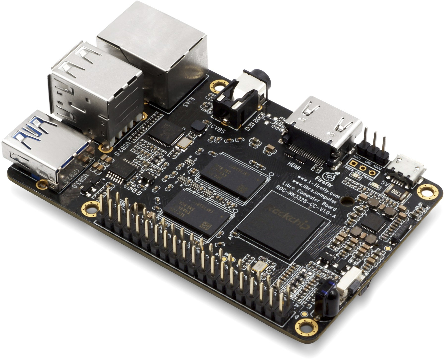
So this board is in cooperation with firefly? Next to the 3 gpio pins you can see the firefly logo. What is a 3 pin adc connector?
Analog-to-digital converter. It’s usually a single pin for mic input on these boards, maybe the 3-pin one means it can be used for line-in stereo audio? I dunno.
@tkaiser
Type-c connectors and cables are still much too costly to make sense on these boards, even crappy, short, USB 2.0 type-c cables cost several dollars.
I wish they’d stuck with the mini-USB standard honestly, it just feels a lot better. I guess it does make your hardware look eight years older though –so does a barrel jack for that matter. I think that’s part of the problem too — marketing people will demand micro USB to make the board look hip and fresh and groovy and IOT-y and whatnot.
@ahrlad
Because on the picture you can see ADC0 / GND /ADC1, I thought it could mean alternative DC. 🙂
@roel
” . We are teaming up with the Firefly team and BayLibre to bridge the gap with additional software support. There are so many boards that people buy that end up in a box somewhere unused due to the lack of software support. We are letting you know now that this will not be one of those. We will be bringing software support for Media Center, Retro Gaming, Desktop Computing, and many other use cases.”
Source indiegogo fund site.
@tkaiser
Please see https://libre.computer/2017/12/03/performance-and-power-consumption-comparison-for-aml-s905x-cc-le-potato-and-raspberry-pi-3-model-b/
The overall current draw profile for RK3328 is similar to S905X. Using ssvb’s cpuburn-a53, the board consumes around 0.7A compared to Raspberry Pi 3’s 1.3A. The Raspberry Pi 3 also suffers from a large voltage drop between the MicroUSB pins and the 5V rail due to the connector, polyfuse, and diodes. This is not an issue if a board is designed properly. Using a real 2.5A power supply, you should be fine for all but the most extreme use cases. If you are using a 1A cell phone power supply, you will hit the aforementioned issues.
I would rather see a laptop style 19.5V input. You’re using switching mode regulators that can handle the input voltage anyway, so why not take advantage of it. With the low power consumption of these boards, the current on that jack would be tiny. (W=V*I, so high V means lower I for a given W)
@tkaiser
Raspberry Pi 3 is designed not to exceed 1.5A. You can’t pull more than 1.5A if you wanted to which leads to numerous issues with power delivery to USB devices. If you mention it, Raspberry Pi fanatics get all upset and the issue never gets addressed. That stupid GPIO low power indicator is about to next to useless if you need 5.5V which no normal power supply can deliver since you will trigger it anytime the CPU clocks past 800MHz.
There are many designs currently on the market with barrel DC in jacks. They forgo input protection altogether and many devices end up dead when a power issues occur. I will not name names of these numerous “better” boards.
@willmore
Future designs will move to USB PD which is 20V with proper negotiation so I think it’s a non-issue long term.
Ok, here my numbers for RK3328 (with ROCK64 limited to 1.3GHz@1300mV DVFS settings):
– sysbench on 4 cores: 2.8W/550mA
– cpuburn-a53 on 4 cores: 6.3W/1250mA
For obvious reasons I question your S905X numbers but it really doesn’t matter that much anyway since why should these consumption figures above have any relevance at all? We’re talking about a board with USB ports that are there to be used by people. It’s not about the board’s own consumption, it’s about the additional consumption generated by the fast USB ports.
I’m looking at these boards only from a user and support perspective.
– Why do users buy them? –> Gigabit Ethernet and USB3 in the meantime known to be pretty fast and making up for a good NAS as fast as any x86 box with GbE
– What will users do? –> Attach a 2.5″ HDD ot the USB3 port
– What happens next? –> All sorts of problems since the engineer’s choice to power through Micro USB encouraged users to do something really stupid: combining shitty phone chargers with crappy Micro USB cables since ‘worked very well with Raspberry Pi all the time’ (why the hell are engineers not able to understand users?)
That’s all I deal with and I will stop further wasting my time with this stuff. If it has Micro USB and needs more than a few hundred mA then it’s a clear sign to not touch this piece of $something ever. Since it’s a support nightmare.
If as I learned today USB-C is too expensive then the only alternative is a barrel plug. If other boards with barrel plug do not implement input protection then do it better. Nothing more to say, I’m sooooo tired of dealing with this Micro USB crap and of course engineers/designers with an imagination limited to their lab environment with a great bench PSU and superiour thick cables totally forgetting about the user reality out there: users encouraged to do it wrong introducing that support mess that’s present with all of these Micro USB equipped fails.
I really couldn’t care less which technical limitations on any of these ultra boring Raspberry Pi boards exist or not. It’s only about user expectations. The RPi foundation instead of fixing the crappy connector simply masqueraded the problem. So RPi users simply do not realize that they run frequency capped almost all the time since those RPi people also took care that users don’t know. The firmware running on the VideoCore caps the frequency of CPU, GPU and VPU cores in undervoltage situations while the kernel running on the ARM cores has not the slightest idea what’s going on.
The ‘firmware’ is cheating both when frequency capping occurs and when throttling occurs. This is how it looks like with a crappy USB cable and a RPi 2 when something demanding starts and input voltage drops below 4.65V:
(see the raspimon link in my first comment above for details). The firmware both decreases the Vcore voltage to 1.2V and the CPU clockspeed to 600 MHz while the kernel is told CPU cores would still run at 900 MHz or 1200 MHz on RPi 3 (that’s the 900/600 mismatch above). And the average RPi user doesn’t notice and is just happy with the situation since he has not the slightest idea that there even is a problem. He is not aware that his powering situation is crap and he runs all the time only with a fraction of possible performance (on RPi 3 it’s exactly half the performance possible since there frequency capping results in 600 MHz instead of 1200 MHz).
Now another SBC vendor starts to sell incompatible boards as drop-in replacement encouraging users to just swap out the board and use their existing PSU + Micro USB cable. And now the problems start since this other board does not implement undervoltage detection/compensation, the board is stuck in a crash/boot cycle (good!) or worse just randomly crashing/freezing and meanwhile corrupting the OS installation as well. This is the stuff we @ Armbian deal every day with these Micro USB fails at the same time not able to explain to users underpowering being the real problem since ‘No, with my RPi it just works fine, the problem can’t be power related’.
Obviously hardware engineers are not able to understand this.
The ‘crap’ word has been used 17 times here 🙂
@tkaiser how about powering over GPIO? Is it a good idea to use DC buck converter for that?
@tkaiser
As for AML-S905X-CC, it runs with 100% stablility with 4.1V coming from the DC power supply so I think MicroUSB is a non-issue for that board at least. I will test the ROC-RK3328-CC and let you know. The fact of the matter is Raspberry Pi and Shenzhen et al. did everybody a dis-service by not properly designing their boards for real world scenarios.
“Obviously SOME hardware engineers are not able to understand this.”
@tkaiser
With for the Raspberry Pi 3, the initial data was all over the place. If you run ssvb’s cpuburn-a53, the Raspberry Pi’s red LED will turn off and the firmware throttle will kick in for all power supplies on the market including Raspberry Pi’s own power supplies. It would immediately drop to 600MHz and any benchmark data would have to be discarded. The final input voltage we were able to get stable benchmark numbers reflecting the Raspberry Pi 3 hardware capabilities was 5.55V. This kept the 5V rail at about 4.8V at full load which is absolutely mind boggling. We have repeatedly flagged this issue with Raspberry Pi but fanboys are like ultra left/right wing fanatics that refuse to have a meaningful discussion.
That’s a very expensive solution to the problem. USB3 type C ports are still pretty rare and those supporting USB-PD are even more rare. And those aren’t even required to support 20V.
Laptop supplies are super cheap–assuming you don’t have a pile of them from old dead laptops. With a simple buck converter, any input >5.5V (up to whatever value the converter can handle) will be fine. That means 12V, automotive power, etc. will be good inputs.
I understand that some small boards might have to compromise, but there’s little excuse for larger boards like this one to have poor power circuitry.
@Tesla
This is not a technical problem but just one of user expectations and so much wasted time with useless support efforts.
If you are aware that powering through Micro USB is a real problem you are always able to buy a good PSU and a good and short Micro USB cable (search for ’20awg micro usb’ on Amazon for example), you can even order them with this board on Indiegogo (and that’s what I would recommend). The problem is that users neither are aware that powering can be a problem nor that when they already use a SBC (most probably a Raspberry Pi) the powering equipment they currently use is very often not sufficient and they’ll run in problems with their new board.
If Libre Computer would add a mandatory 5V/2.5A PSU with low resistance fixed Micro USB cable to every board they want to sell a) the problem wouldn’t exist and b) they wouldn’t sell that much since the average RPi user they try to address wants to use his old phone chargers and Micro USB cables lying around in his drawer (good for 500mA max). And when they unbox their new board and combine it with their old PSU/cable the problems start with a user not able or willing to understand why something that worked ‘flawlessly’ with a Raspberry Pi (almost always not true) now should be a problem with the new and ‘better’ board that should replace the RPi.
PS: powering via GPIO pins depends on board design, sometimes it bypasses some input protection (eg. Raspberry Pi), sometimes not (eg. Orange Pi), sometimes it might not even be possible (not aware of an example).
@Tesla
I’m not tkaiser, but… My small testing cluster:
ODROID-C2 (barrel connector)
Orange Pi PC (barrel connector)
Orange Pi PC2 (barrel connector)
Orange Pi One (barrel connector)
The power supply is a repurposed ATX supply that’s good for 20A on the 5V rail.
I certainly expect not to have power issues. 🙂
I don’t have a problem with the micro-usb connector as long as you know the limitations of it and if it is possible to safely power the board in another way if necessary. I can understand the idea the boards should fit a rpi case, that’s why I backed the tritium boards because I wanted to replace my rpi b+ (in a to expensive case) with a more powerfull board that has decent support (sunxi).
On the other side I don’t support the miro-usb at all, as all rpi’s I saw in action displayed the lightning symbol. But none of the users did care, they think it’s a part of raspbian. If I say they have to use a proper psu instead of their laptop usb port and use a short quality usb cable, they don’t even listen. Poeple don’t understand ohm’s law and the fact that P=U*I.
Not so long ago some guy would show me his rpi with Windows IOT. The board kept on rebooting (due to lack of power, but he didn’t know/realize) He blamed the Pi instead of windows and he was probably wright.
I wish Firefly would produce an updated version of their discontinued OpenWRT FireWRT with similar spec to the article on it on https://www.cnx-software.com/2015/05/14/firewrt-is-an-openwrt-802-11ac-board-powered-by-mediatek-mt7621a-processor/ perhaps with a newer more integrated WiFi than the MT7621A/MT7602E/MT7612E chipset. (it used a barrel connector & SPI Flash memory)
Not a single person being aware of the micro-usb connector being such a pile of crap has any problem with it (buy an 20AWG rated cable and you’re done). It’s the remaining 99.99999% of people who don’t know what’s happening.
@willmore
There’s no reason why PD should be rare though, and it does 100% solve the aforementioned problems. Functionally your standard 5V USB charger will be one step-down voltage regulator from about 20V plus an 8 pin microcontroller to handle basic negotiation. A PD charger will beef up the microcontroller a little to maybe 16 pins and the voltage regulator needs to be adjustable. The SBC side is even easier, if you draw less than 15W an 8 pin MC for comms will do.
The problem is that we need copycat manufacturing to catch up and reduce the price of a fully functioning design that someone else tested properly to practically 0. Looking into it, the STUSB4710 is a good match but that came out in April 2017. I reckon in 2018 we’ll see the price of PD plummet and by 2019 it’ll be the norm at most levels.
Or just provide a 2-pin JST connector just behind the micro-usb connector and clearly say “never ever plug anything in the USB ports when the board is powered via micro-USB, you MUST provide a real 5V/3A power source via the extra 2-pin connector”. Then it becomes simple for everyone.
I understand how convenient micro-USB is, we all have plenty on our desks waiting to be plugged somewhere. Some of us know how crappy it is. Recently though I got hit with barrel connectors just because the cables I bought on e-bay had a total 1-ohm resistance and were not even able to boot my nanopc-t3. Cables are a real pain these days!
I always though USB-C has been designed with 2 modes not requiring PD (USB power delivery): 5V@1.5A and 5V@3A do not require PD but only some pull-down resistors? And I really don’t see the point to even implement this (limiting the board’s consumption in case the other end of the cable signals only being capable of 1.5A) since with this Micro USB crap currently people try to squeeze 2.5A out of a connector rated for 1.8A max combined with cables rated for 0.5A. Can it get worse with a simple USB-C receptacle on the PCB combined with 3A PSU using a fixed cable with thick enough wires to avoid voltage drops?
Better but the rock then, its cheaper and already availible
Would this old thing help or make it worse?
https://www.adafruit.com/product/2789
@Jeroen
Once shipping is taken into account the price for the 1GB version is only slightly different, and you do get DDR4 which may help with some 4K HDR videos.
Libre Computer may also spend more resources on software than Pine64 (TBC), based on @theguyuk‘s comment.
Isn’t part of the problem the very connector itself, though? How much current would it let through before it fuses?
Of course the connector itself is a problem since rated only for 1.8A maximum current. But usually the part behind the connector on the PCB is also problematic since not only the contacts inside the receptacle are too tiny but also the contact areas on the PCB: https://forum.mqmaker.com/t/miqi-based-build-farm-finally-up-and-running/605/10
But normally crappy cables prevent the connector becoming the main bottleneck (wire resistance ‘winning’ over contact resistance). And when people are finally aware of the problem and try to buy good Micro USB cables with a nice low AWG rating then this happens: http://nerdralph.blogspot.de/2016/06/when-does-18-26-when-buying-cheap-cables.html
@tkaiser
I’m going to print “you can’t say it is fake just because it is thin” on a t-shirt.
I start to think that new dev boards won’t focus on the $10-15 price range anymore. It’s so sad, because a rockchip board for $15 with 1GB RAM is very feasible.
@tkaiser
They use a 3.5mm barrel jack 5v 3amp…that goes to your wall power. That image is not a ROCK64! I got mine couple weeks ago works fine.
I know, the Rock64 fortunately does NOT use crappy Micro USB for DC-IN while the picture above shows the Renegade with a Micro USB connector to be powered and Libre Computer’s product page clearly states ‘MicroUSB Power In’
So are you telling you hold one in your hands and they replaced Micro USB with something sane? The same 3.5mm/1.35mm barrel plug as Rock64?