
A few years ago, we already saw it was possible to transmit color signals over NTSC using an ESP8266 board with the signal received on a TV with an analog tuner. CNLohr had to connect an antenna to the I2S pin of his ESP8266 module, and disable WiFi.
But surely we should be able to do the same with ESP32, and potentially even better thanks to the two cores. That’s exactly what Bitluni successfully managed by connecting his LoLin32 board to the composite input of his TV with one handling the TV signal output (in grayscale) and the other core rendering 3D objects in real-time.
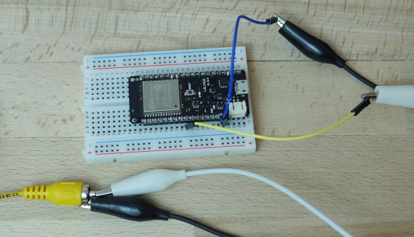
But any ESP32 board could be use instead. The hardware connection is very easy. We just need two wires, one connected to the GND pin and outer part of the RCA connector, and the other connected to GPIO 25 (DAC1) and the inner part of the RCA connector.
The software is more complicated, and basically some Arduino code leverages I2S to push data at high speed to the DAC which then converts the digital signal into analog signal fed to the TV. The 3D rendering engine is able to draw 2k triangles at CGA (320×200) resolution, and if I understand correctly, he was memory limited in what he could do, so maybe high resolution 3D rendering is possible on boards with external PSRAM (TBC). The theory and full details about the implementation can be found on Bitluni website. Watch the video below for a demo, and a quick explanation of how it all works.
Thanks to Karl for the tip.

Jean-Luc started CNX Software in 2010 as a part-time endeavor, before quitting his job as a software engineering manager, and starting to write daily news, and reviews full time later in 2011.
Support CNX Software! Donate via cryptocurrencies, become a Patron on Patreon, or purchase goods on Amazon or Aliexpress


Slightly off topic but this reminds me the original Sinclair ZX Spectrum used some of the z80 CPU time for its display. The designer even received a patent on the design
”
Hardware design was by Richard Altwasser of Sinclair Research, and the outward appearance was designed by Sinclair’s industrial designer Rick Dickinson.[6]
Video output is through an RF modulator and was designed for use with contemporary television sets, for a simple colour graphic display. Text can be displayed using 32 columns × 24 rows of characters from the ZX Spectrum character set or from a set provided within an application, from a palette of 15 shades: seven colours at two levels of brightness each, plus black.[10] The image resolution is 256×192 with the same colour limitations.[11] To conserve memory, colour is stored separate from the pixel bitmap in a low resolution, 32×24 grid overlay, corresponding to the character cells. In practice, this means that all pixels of an 8×8 character block share one foreground colour and one background colour. Altwasser received a patent for this design.[12]
An “attribute” consists of a foreground and a background colour, a brightness level (normal or bright) and a flashing “flag” which, when set, causes the two colours to swap at regular intervals.[11] This scheme leads to what was dubbed colour clash or attribute clash, where a desired colour of a specific pixel could not necessarily be selected. This became a distinctive feature of the Spectrum, meaning programs, particularly games, had to be designed around this limitation. ”
Ref Wikipedia.
Video made my day. Respect!
Very nice!
From the performance values I’ve heard of for the PSRAM, don’t expect it to help this application at all. The BW to it is very low and the latency is pretty high. It’s not going to be of use in a racing-the-beam type of application like this.
I higher memory ESP chip would help if they ever make one of those. 😉