
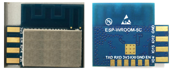
You’d think by now we’d have enough ESP8266 or ESP8285 WiFi modules, but based on an FCC listing, we now know that Espressif Systems has been working on another ESP8285 WiFi module – ESP-WROOM-5C – designed to be side-mounted.
 ESP-WROOM-5C specifications:
- SoC – Espressif Systems ESP8285
- Wi-Fi
- 802.11 b/g/n WiFi 4 @ 2412 MHz ~2462 MHz;
- Station/SoftAP/SoftAP + Station modes
- WPA/WPA2 security with EP/TKIP/AES encryption
- PCB antenna
- Peripheral interface
- I2C/IR Remote Control
- GPIO/PWM
- Operating voltage – 2.7V ~ 3.6V
- Operating current – Average: 80 mA
- Minimum current delivered by power supply – 500 mA
- Dimensions – 19 x 16 x 3.2 mm
- Temperature Range – -40°C ~ 105°C
- Reliability Tests – HTOL/HTSL/uHAST/TCT/ESD
The module supports firmware upgrade over UART or OTA (Over-The-Air). Software development can be done with the IDF SDK for custom firmware, but “Cloud Server development” is also possible, and an Android/iOS app can be provided for user configuration.
There isn’t any other public information about ESP-WROOM-5C module at this stage other than on the FCC page, where you’ll find the user manual (PDF) for more technical details.
Thanks to Mikkel for the tip

Jean-Luc started CNX Software in 2010 as a part-time endeavor, before quitting his job as a software engineering manager, and starting to write daily news, and reviews full time later in 2011.
Support CNX Software! Donate via cryptocurrencies, become a Patron on Patreon, or purchase goods on Amazon or Aliexpress


I don’t understand, what do you mean by side-mounted?
I’m not 100% sure. I adapted the title from the following sentence in the user manual “Espressif now offers a side-mounted module ESP-WROOM-5C based on ESP8285.” I suppose it means it could be inserted in the main board, a bit like a USB stick, instead of being soldered like most other modules.
The note at the bottom of table 2-1 on page 6 of the PDF says:-
Pins 1 ~ 8 are pluggable pads that can be welded to your own development board, while pins 9 ~ 15 are reserved for testing and cannot be welded to the development board.
…which clears up things a bit. There’s also a recommended pad layout (for the motherboard) later in the document.
To get a smaller footprint on the PCB and to (probably) increase the wifi performance the module is mounted vertically on the PCB. Afaik fiddling the module into the PCB and solder it can only be done by hand. So they are targeting low volume products..?
Or will they try to get into the OEM iot-cloud-market where they sell preprogrammed ESPs, cloud hosting and the apps (like ipowerful or smart life) ?
And here is a picture of such side mounted module:
It’s confusing. The user manual PDF suggests the board should be plugged in to a mainboard via the 4 sticking-out edge pads (actually 8 pads, double sided) i.e. the image in this article needs rotated 90 degrees, whereas your linked image shows the board connected via the 6 ‘test pads’ along the other edge. Weird.
I don’t think the image is of exactly this module.
The six pads is for programming the module, maybe with pogo pins. The eight pads is for using the module after it programmed, maybe by plugging it like computer RAM or old game cartridge.
I guess that it is supposed to be plugged inside a socket. This is great for products with optional WiFi.