
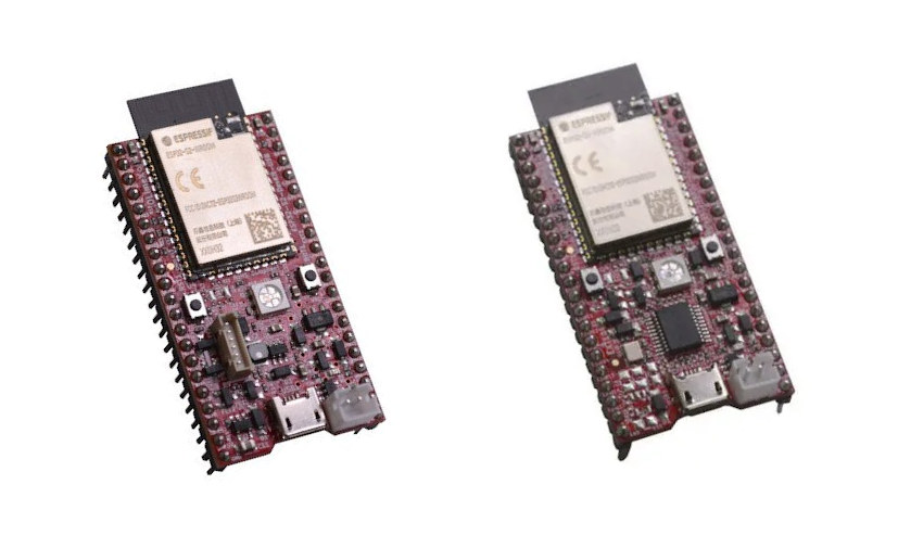
Last year, Olimex introduced ESP32-S2-DevKit-LiPo and ESP32-S2-WROVER-Devkit-LiPo boards optimized for battery-powered applications with as little as 30uA deep sleep power consumption.
ESP32-S2 processor comes with a USB OTG interface, but at the time, Espressif Systems ESF-IDF SDK did not support programming via the built-in USB interface, so Olimex added CH340T USB to serial converter for programming.
The good news is that the SDK can now support USB programming without an external chip, so the company designed new versions of the boards without a USB to serial chip with namely ESP32-S2-DevKit-LiPo-USB and ESP32-S2-WROVER-Devkit-LiPo-USB boards.
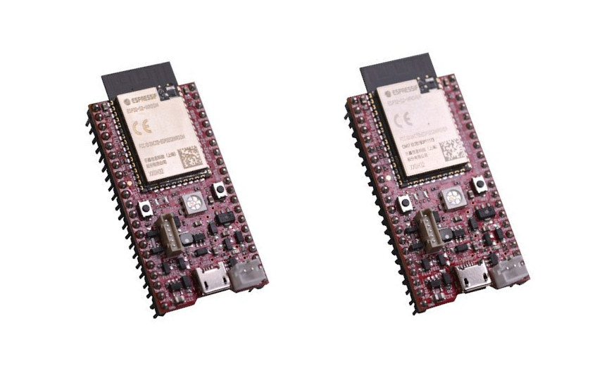
The specifications are basically the same as previously except for the removal of the USB to serial chip, support for USB OTG, and even lower power consumption:
- Wireless module:
- ESP32-S2-DevKit-LiPo – ESP32-S2-WROOM with Espressif ESP32-S2 single-core 32-bit LX7 microprocessor up to 240 MHz with 128 KB ROM, 320 KB SRAM, 16 KB SRAM in RTC, 4MB SPI flash
- ESP32-S2-WROVER-Devkit-LiPo – ESP32-S2-WROVER – same as above plus 2MB PSRAM
- Wireless connectivity – 2.4 GHz 802.11 b/g/n WiFI 4 up to 150 Mbps
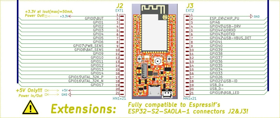
- Expansion – 2x 20-pin I/O headers with SPI, I2S, UART, I2C, touch sensors, PWM, etc… (pin-to-pin compatible with ESP32-S2-SAOLA-1)
- USB – Micro OTG USB port
connected via CH340T USB to serial chip - Misc – RGB LED, Reset button, user button, 6-pin header for programming
- Power Supply
- 5V via micro USB port or I/O pins
- 2-pin header for LiPo battery plus battery charging and monitoring circuit, external power supply sense
- Power consumption as low as 20 uA in deep sleep mode, 65 uA for ESP32-S2-WROVER
One may think removing a chip and connecting the USB interface directly to the micro USB port may be a trivial task, but Olimex explains it was quite complicated as they wanted to keep the LiPo charger and battery circuit, and notably be able to charge the battery in USB OTG mode, while providing 5V in host mode.
Since the boards are open-source hardware, you can also check out the schematics posted to Github, where you’ll also find an Arduino sketch controlling the RGB LED. It should however be noted that while the hardware supports USB device and host modes, but USB host functionality is still missing in ESP-IDF SDK.
You can buy the boards for 6.95 and 7.95 Euros respectively, and find additional links to documents on Olimex website.

Jean-Luc started CNX Software in 2010 as a part-time endeavor, before quitting his job as a software engineering manager, and starting to write daily news, and reviews full time later in 2011.
Support CNX Software! Donate via cryptocurrencies, become a Patron on Patreon, or purchase goods on Amazon or Aliexpress


This is 20uA not 20nA
Open source schema. Expect clone from Chinese.
Not necessarily. You can search for one of Olimex’s presentations/videos on the topic (e.g. Open Source Hardware. Why we do it, why it matters?). There are benefits in doing OSHW and in certain cases they far outstrip the drawbacks (e.g. has Arduino bankrupted?). As for ultra-low-cost bad quality clones – these are always there, no matter if the design is public or not, so it doesn’t really matter in the grand schema of things. This board could easily (and cheaply) be reverse-engineered. And ultra-low-cost bad quality isn’t Olimex’s market anyways, so there is no intersection 🙂 (They do relatively low… Read more »
It’s also important what the target market size is.
Someone in the business may shed more light on the economics of this, but I imagine that for ultra low cost boards to be viable one needs to produce them in batches of at least 100K pieces (just a wild guess from an end-user’s standpoint).
a legend tell CH340T is under metal enclosure 😉
I looked at the schema, and the design is really nice. It covers all use cases commonly encountered in IoT, experimentation and development. The PCB silkscreen recalls the pinouts. I’m seeing one small change which would have improved it further, the RGB_LED signal ought to have been taken from the RGB LED’s DOUT instead of the DIN, because using it for an external light strip will necessarily force the on-board LED to mimmick the external one, while chaining them after it could have simplified the management of a LED strip by simply skipping the first one. Probably going to buy… Read more »
I could see a “LED ENABLE” solder jumper on the back of the board.
Not exactly the same as what you envisioned, but could probably be used to disable the onboard LED and use any externally attached LED strips only.
Ordered on Saturday, already arrived, not flashed yet but I’m pretty sure I’ll find good projects to install on them 🙂