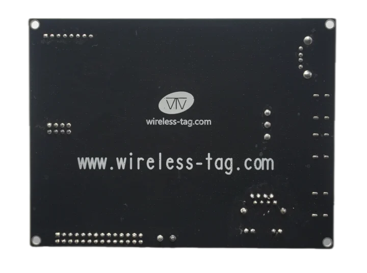
All ESP32-P4 boards and devkits we’ve covered so far rely on ESP32-C6 for wireless connectivity, but the Wireless Tag WT99P4C5-S1 differs in that it pairs the ESP32-P4 RISC-V SoC with an ESP32-C5 wireless module featuring dual-band WiFi 6, Bluetooth LE 5.0, and an 802.15.4 radio for Zigbee, Thread, and Matter connectivity.
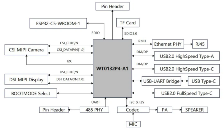
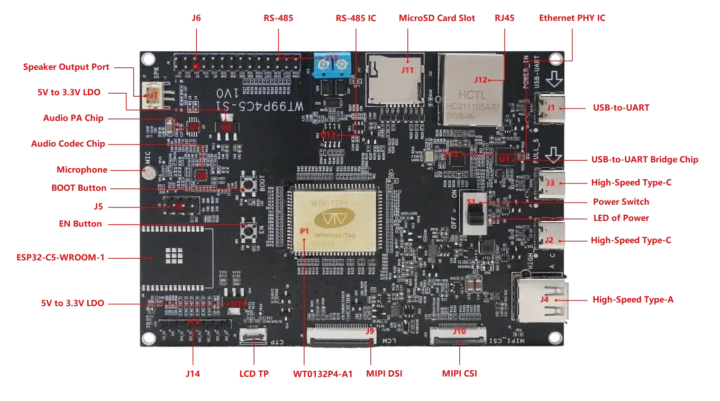
The board also features MIPI DSI and CSI connectors for a display and a camera, GPIO headers for the ESP32-P4 and ESP32-C5 modules, a microSD card slot, a Fast Ethernet port, a built-in microphone, a speaker connector, an RS485 terminal block, and a few USB ports for data and debugging.
Wireless Tag WT99P4C5-S1 board specifications:
- Core module – Wireless Tag WT0132P4-A1
- SoC – Espressif Systems ESP32-P4
- CPU
- Dual-core 32-bit RISC-V HP (High-performance) CPU @ up to 400 MHz with AI instructions extension and single-precision FPU
- Single-RISC-V LP (Low-power) MCU core @ up to 40 MHz with 8KB of zero-wait TCM RAM
- Memory
- 768 KB HP L2MEM (for dual-core CPU), 32 KB LP SRAM, 8 KB TCM (for LP MCU core)
- 16MB or 32MB PSRAM
- Storage – 128 KB HP ROM, 16 KB LP ROM
- GPU – 2D Pixel Processing Accelerator (PPA)
- VPU – H.264 and JPEG codecs support
- CPU
- Storage – 16MB NOR flash
- Dimensions – 25 x 20mm
- SoC – Espressif Systems ESP32-P4
- Storage – MicroSD card slot
- Display I/F – MIPI DSI connector for display + “LCD TP” connector for touchscreen
- Camera I/F – MIPI CSI connector
- Audio
- Speaker connector
- Built-in microphone
- Audio amplifier chip
- ES8311 audio codec
- Networking
- 10/100Mbps Ethernet RJ45 port
- Optional ESP32-C5-WROOM-1 wireless module for dual-band 802.11ax WiFi 6, Bluetooth 5.0 LE, and 802.15.4 (Zigbee 3.0 and Thread 1.3)
- USB
- 2x USB Type-C ports
- 1x USB Type-A port
- Serial – 2-pin RS485 terminal block using SIT3088EESA chip
- Expansion
- 28-pin GPIO header (J6) for ESP32-P4
- 8-pin GPIO header (J14) for ESP32-C5 with 7x GPIO, C5 EN pin
- 8-pin GPIO header (J5) for ESP32-C5 with UART, ADC, 3.3V, GND
- Debugging – USB-C port via USB-to-UART chip
- Misc
- Power switch
- BOOT and EN buttons
- Power LED
- Power Management
- 5V DC input via USB-C port
- 5V to 3.3V LDO
- Dimensions – TBD

Documentation is limited to an 11-page English datasheet for the ESP32-P4 module and a 13-page datasheet in Chinese for the board itself, both of which are available for download on the product page. We’re told to program the board with the ESP-IDF framework, and there’s also a link to code samples on GitHub (https://github.com/wireless-tag-com/WT99P4C5-S1/tree/master/examples/WT99P4C5). However, that link does not work, probably because they haven’t made it public yet, and I can’t find any references to “WT99P4C5” or “ESP32-P4” on the Wireless Tag GitHub account.

The Wireless Tag WT99P4C5-S1 board is sold on AliExpress for $24.99 or $25.01 on another shop with an ESP32-C5-WROOM-1 module soldered on the board. I could not find the WT0132P4-A1 ESP32-P4 module on AliExpress, but it is sold on the company’s online store for $5 plus shipping.

Jean-Luc started CNX Software in 2010 as a part-time endeavor, before quitting his job as a software engineering manager, and starting to write daily news, and reviews full time later in 2011.
Support CNX Software! Donate via cryptocurrencies, become a Patron on Patreon, or purchase goods on Amazon or Aliexpress. We also use affiliate links in articles to earn commissions if you make a purchase after clicking on those links.


