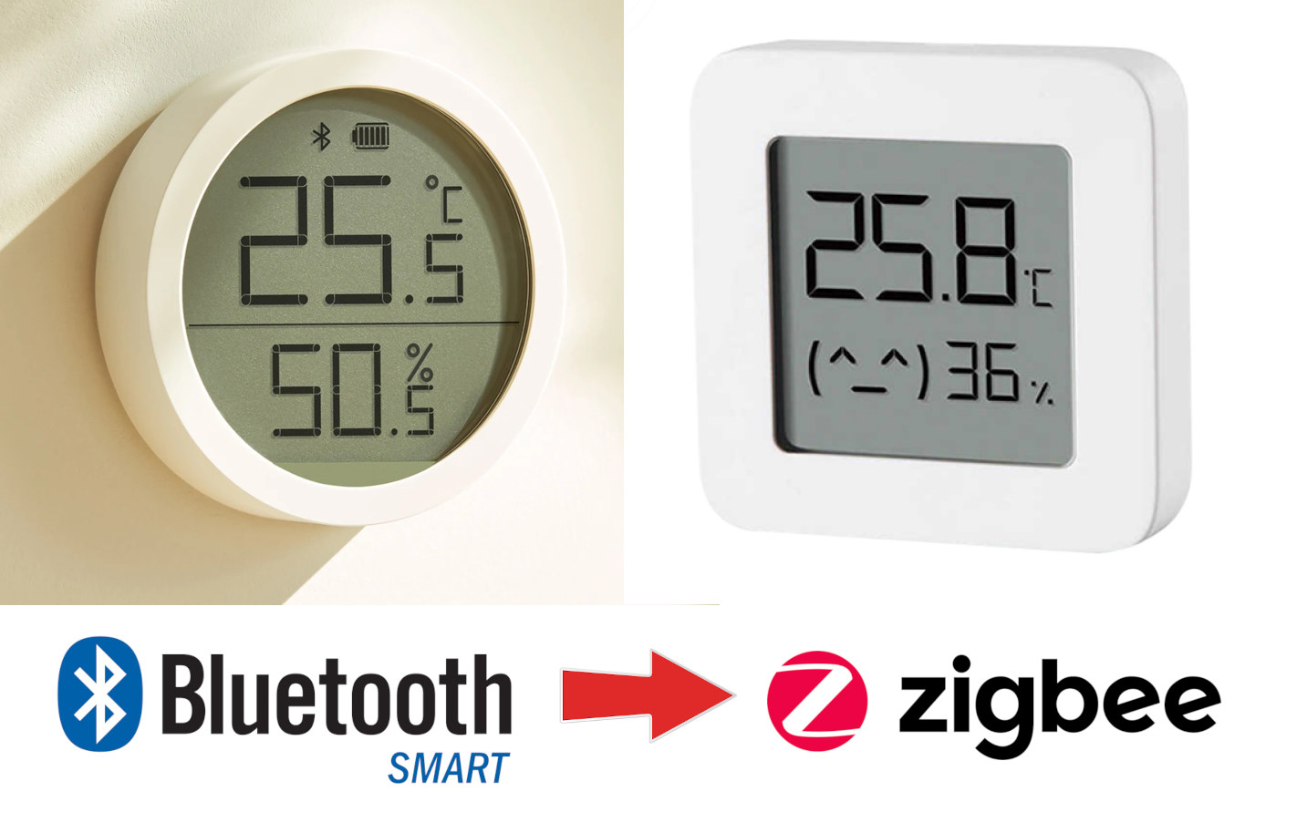
Archive

Posts Tagged ‘hack’

Design West Summit – 23-25 April 2013

April 9th, 2013 No comments

design_west_2013Design West 2013, previously known as the Embedded Systems Confertence, will take place later this month, on 23-25 April to be exact, at San Jose McEnery Convention Center in San Jose, California, US. The event will be divided into 22 tracks dealing with software development, hardware design, operating systems, security and more:

  • Android Certificate Program – Two-day hands-on embedded android workshop.
  • Black Hat Summit – The Black Hat Embedded Security Summit will provide electronics professionals with essential information and tools, as well as a forum for the discussion and evaluation of the latest solutions for securing their embedded systems. Training courses will focus on topics such as Network Security, Incident Response, Web Application Security, and Exploit Development.
  • Connectivity and Networking – The Connectivity and Networking track educates design engineers on wired and wireless communications, spanning need-to-know topics from essentials of USB device development to antenna and RF system design.
  • Debugging and Test – This track features a mix of lectures focusing on useful insights on troubleshooting real world embedded software, and tips and tricks with highly practical takeaways that embedded systems designers can apply immediately.
  • Embedded Android – This track covers the tradeoffs of Android versus Linux in a real-world case study, teaches engineers how to streamline Android implementation on embedded systems, and provides information on how to apply USB technology and provide connectivity to various configurations of Android platforms.
  • Hardware: Design, I/O, and Interfacing – This track examines how to ameliorate the challenges associated with design element such as the interface between hardware and firmware; synchronizing I/O, integrating embedded vision and motion control, and leveraging existing sensor drivers.
  • Internet of Things – This track covers some of the specific challenges and opportunities for embedded designers, including today’s fragmented sensor and device market, the move from IPv4 to IPv6, and the return to resource-constrained embedded systems.
  • Linux Kernel and Operating Systems – The Linux Kernel and Operating Systems Track focuses on the kernel itself, and the operating system and programs running above it. Sessions cover best practices for engineers to leverage the use of open source software within embedded systems while avoiding common pitfalls, plus a session showing how Linux, though not a real time kernel, is likely good enough for your application.
  • Low-Power Design – The Low-Power Design track covers the latest techniques to conserve power at the system; architectural and component level as well as the advantages and trade-offs of different power optimization techniques.
  • Processors and Programmable Devices – The Processors and Programmable Devices track focuses on embedded systems that feature the use of processors (MPUs, MCUs, DSPs) and/or programmable devices (FPGAs, Programmable SoCs).
  • Programming – The Programming track focuses on embedded system programming languages, tools and techniques. Sessions provide practical tips and tricks and actionable information that developers can apply immediately to their code.
  • Prototyping – The Prototyping track focuses on the science and art of rapidly creating embedded systems for proof of concepts, demonstrations and iterative product developments.
  • Real Time Operating Systems – This track focuses on delivering real-time performance with the assistance of a real-time scheduler and related tools and techniques. Sessions include practical information on the design of real-time embedded systems that will be timely and predictable, design options for achieving real time without an RTOS, and the application of RTOS in safety critical applications.
  • Safety, Security and Hacking Embedded Systems – The Safety, Security, and Hacking Embedded Systems covers the latest techniques for designing and managing more secure systems. Sessions cover a mixture of hacking history, security knowledge, techniques for building more secure embedded system, and coping with the special case of Android.
  • Software Architecture and Design – Using practical, real-world advice from experts, this track will guide you through everything from requirements and specification development techniques, to optimizing your multicore and user-interface design. Agile design techniques will also be introduced.
  • Software Development – The Software Development Track will guide you toward a more disciplined approach to software development to improve performance, while emphasizing agility. A special session on common traps and pitfalls when developing real-time software will underscore the importance of such approaches.
  • Systems Engineering – The Systems Engineering Track’s objective is to improve analytical skills, impart an enhanced understanding of the impact of your engineering decisions on others on the design team, and the impact of other decisions on you. Engineers will learn the benefits of looking at the big picture, in addition to focusing only on the detail.
  • Hello World! – Track engineers share their embedded design experiences and provide information that will help you bring your ideas to life more quickly and successfully.
  • Lessons and Lessons Learned – Engineers share their successes and failures along with some practical tips, tricks, and how-tos to jump start your next big embedded systems project.
  • Connected Devices – Learn about the whacky wonderful future of mobility and learn about some real world examples of products with embedded systems that are already talking to the cloud.
  • Tech Fundamentals – This 3-day series consists of 18 45-minute sessions designed specifically for engineers who are new to embedded or experienced embedded engineers who want an introduction to topics outside of their core expertise. These practical sessions delivered in a tutorial format cover topics ranging from Embedded 101 to Analog for Digital Designers to Why the Programming Language C matters.
  • Hands-on Speed Training – Attendees can get some drive time on the latest development boards, hardware, and software tools and face time with expert engineer-trainers.  Developments boards include Arduino, Beaglebone, Raspberry Pi… software tools include Microchip MPLAB X, TI WEBENCH Power Designer, etc..

To select the sessions, the best way is to use the schedule builder available on UBM website.

If you plan to only access the expositions, attend a few of the many vendor-sponsored sessions, and listen to keynotes, the pass (Expo Only Pass) is free and you only need to register. For details about the other pass see table below.

All Access
Pass
Expo
Plus Pass
Expo Only Pass Black Hat
Summit
Advanced | Feb 16 – Apr 18 $1,999 $199 Free $1099
Onsite | April 19 – 25 $2,299 $199 Free $1199
Conference Sessions
April 21 – April 25
Check
Black Hat Conference Sessions
April 23 – April 24
Check Check
Monday Workshops Check
Monday Lunch Check
Vendor Sessions
April 22 – April 25
Check Check Check Check
Keynotes
April 23 – April 25
Check Check Check Check
Expo
April 22 – April 25
Sketch to Shenzhen, Fundamentals, and Hands-On Training Lab Included
Check Check Check Check
Parties & Giveaways
April 22 – April 25
Check Check Check Check
DESIGN West Conference Proceedings Check Check
Black Hat Summit Proceedings Check Check
Android Certification
April 22 – April 23
Check
IEEE Certification
April 22 – April 25
Check
Expo Plus Extras

– 3 Class Passes
Check

Further details are available on Design West Official Website.

Digg This
Reddit This
Stumble Now!
Buzz This
Vote on DZone
Share on Facebook
Bookmark this on Delicious
Kick It on DotNetKicks.com
Shout it
Share on LinkedIn
Bookmark this on Technorati
Post on Twitter

How to Access the Serial Console in MK808 mini PC

January 30th, 2013 3 comments

Omegamoon has done a pretty neat hack on MK808 Rockchip RK3066 mini PC to connect a Sparkfun USB to TLL board and access the serial console for bootloader and kernel debugging. The first thing he had to do was to open the device, remove the heatsink, and locate the Rx/Tx pads on the board.

3 Wires connected to Ground (Blue), Rx (Green) and Tx (Yellow)

3 Wires Connected to Ground (Blue), Rx (Green) and Tx (Yellow)

The Rx and Tx pins are accessible through pads, not via through holes, so it’s just a little more difficult to solder, but nothing too challenging. He and his brother also soldered another cable to the ground. Then they inserted a 6-pin header via the ventilation holes of the device, soldered the 3 wires to the header, and fix the latter to the casing.

MK808 UART Pin Header

Finally, they just inserted the debug board in the pin header, connected the USB cable to their PC, and started minicom (or equivalent) to start accessing the serial console.

MK808 UART Debug Board

I think that looks awesome. You can find all the steps, and high resolution pictures on Omegamoon blog.

Digg This
Reddit This
Stumble Now!
Buzz This
Vote on DZone
Share on Facebook
Bookmark this on Delicious
Kick It on DotNetKicks.com
Shout it
Share on LinkedIn
Bookmark this on Technorati
Post on Twitter
Categories: Hardware, Testing Tags: hack, how-to, mini-pc, mk808

Beaglebone: The Perfect Telemetry Platform? – ELCE 2012

January 15th, 2013 No comments

Matt Ranostay, technical staff at Ranostay Industries, gives a presentation about a telemetry system based on Beaglebone at the Embedded Linux Conference Europe on November 5, 2012.

Abstract:

The author will discuss his ongoing and other team members efforts to develop hardware and software that reports sensor data to the community. This talk will be split into several parts a) types of useful sensors b) hardware design of Beaglebone capes c) and telemetry reports to Pachube/Cosm. Demonstrating that in the new world of cheap prototyping boards with I2C, GPIO, and SPI that anyone can setup a decent monitoring system for home security, automation, and weather reporting. There will be a live demo of prototype geiger counter + weather station.

The audience targeted is the professional hobbyist who likes to hack on microcontrollers in their spare time. It will take little to medium knowledge of electrical engineering to follow this talk.

Telemetry System (Weather Station + Geiger Counter) Block Diagram

Telemetry System (Weather Station + Geiger Counter) Block Diagram

You can download the slides for this presentation, and demo source (Python) is available on Github. There are also many other references at the end of the presentation slides.

Digg This
Reddit This
Stumble Now!
Buzz This
Vote on DZone
Share on Facebook
Bookmark this on Delicious
Kick It on DotNetKicks.com
Shout it
Share on LinkedIn
Bookmark this on Technorati
Post on Twitter

Rockchip RK3066/RK30xx Processors Documentation, Source Code and Tools

November 4th, 2012 27 comments

Rockchip RK3066 (part of RK30xx family) is a Chinese dual ARM Cortex A9 SoC targeting multimedia products such as tablets (e.g. Cube U30GT), mini PC (e.g UG802, MK808) and in theory set-top boxes, but I can’t find any products based on this Rockchip processor. It seems mini PCs/ HDMI TV sticks have taken over this market.

RK3066 Processor

The processor features two ARM Cortex A9 clocked at up to 1.6 Ghz with a quad core Mali-400MP GPU. It can support 1080p (3D) encoding/decoding, provides HDMI 1.4a, VGA, composite, component and LVDS video outputs (Dual display support),  USB 2.0 Host and OTG ports, a MAC interface (Ethernet), and much more…

RK3066: Dual core Cortex A9, Video encoder/decoder, JPEG decoder/encoder, Peripherals

Rockchip RK3066 Block Diagram (Click to Enlarge)

Here are the key features of Rockchip RK3066 processor:

  • Dual Core A9 + Quad Core Mali-400MP GPU
  • 2 banks, 8/16 bit Nor flash / SRAM interface
  • 8 banks, 8/16 bit async NAND flash, LBA NAND flash and 8-bit sync ONFI NAND flash, all up to 60-bit hardware ECC
  • 2 GB space for 2 ranks, 16-bit / 32-bit DDR3-800, LPDDR2-800 and LVDDR3-800
  • 3 channels SD/MMC interface to support MMC 4.1 and SD3.0
  • 2 channels TFT LCD interface with 5 layers and 3D display with resolution up to 1920×1080
  • HDMI 1.4 to support 1080p@30 3D video
  • 2 channels 8-bit CCiR656 interface and 10-bit/12-bit raw data interface
  • Audio interfaces: 2 x 2ch  I2S/PCM, 1 x 8ch I2S/PCM interface and SPDIF interface
  • 1x USB OTG 2.0 interface and 1x USB 2.0 Host interface
  • 10/100M RMII interface
  • High-speed ADC interface and TS stream interface
  • Peripheral I/F: 5x I2C, 4x UART, 2x SPI and 4x PWM.
  • Video decoder supporting MPEG-1, MPEG-2, MPEG-4,H.263, H.264, AVS, VC-1, RV8/RV9/RV10, VP6/VP8, Sorenson Spark and MVC codecs.
  • Video encoder supporting H.264 ([email protected], [email protected], [email protected]), MVC and VP8
  • JPEG decoder/encoder

The chip contains a 10 KB internal bootROM that support system boot from 8bits/16bits Async Nand Flash, SPI0 interface and eMMC interface. So if you were expecting to be able to boot from SD card like for AllWinner A10, you’re out of luck. The ROM also supports system code download by USB OTG and  UART0 in CPU system.

Rockchip usually provides close to zero information about their processors on their website, so most of the information must be gathered from videos, blog articles or leaked documents.

RK3066 Development Boards and Documentation

Rockchip does appear to have some development boards, but I could not find any information apart from the picture below (Source) which shows RK3066 set-top-box reference design board. There must also a MID (Tablet) reference design since the schematics (below) have been leaked ,as well as smartphone development boards as there are mentioned in the source code.

rk3066_box_v1.0 development board

Rockchip RK3066 Set-top Box Reference Design

Documentation is sparse by there’s at least 3 interesting documents that have been leaked (found via ArmTvTech Forums):

  • RK30xx_TRM_Rev2_0_p25_38.pdf – Page 25 to 38 extracted from RK3066 Technical Reference Manual (TRM) revision 2.0 just showing the detailed features of the processor. Better use RK3066 datasheet brief below that contains the same information (and more) and is searchable.
  • RK3066_MID.pdf – Schematics for RK3066 reference tablet (RK3066_REF_2CELL). See block diagram below.
  • RK3066_datasheet_brief.pdf – RK3066 “datasheet” (46 pages) giving a detailed description of the processor processor features,  pinout and electrical characteristic. Don’t expect to find any information about registers in this document.

RK3066 MID Block Diagram (Click to Enlarge)

This documentation is good if you want to better understand the features of the processor, find the connection on the boards (e.g. UART), but unfortunately they do not help much when it comes to software development.

RK3066 Linux Kernel Source Code

Rockchip and the companies developing products based on their processors usually drag their feet to release the GPL source code. bq, a Spanish company, appears to be the first company to release the GPL source with RK3066 devices, more exactly their bq Edison and Edison 3G tablets.

They released the source as a tarball (GPL_Edison.tar.gz), but omegamoon imported the code to his github account, and added what’s necessary to build the kernel for MK808 mini PC. Please note that only the Linux kernel source code was released, and apparently the bootloader and no part of Android fall under the GPL license…

As the .config in the root directory is for MK808 at the time of writing, I gave it a try as follows:

git clone https://github.com/omegamoon/rockchip-rk30xx-mk808.git
cd rockchip-rk30xx-mk808
make -j 12 CROSS_COMPILE=arm-linux-gnueabihf- uImage
make -j 12 CROSS_COMPILE=arm-linux-gnueabihf- modules

and was able to build the code successfully on a Debian Wheezy 64-bit build machine. The first time it actually failed because uuencode utility was missing. If you encounter the same issue you can install it with apt-get:

sudo apt-get install sharutils

I did not try the kernel since I don’t have RK3066 hardware, but the guys at ArmTvTech appeared to be successful.

I always interesting to look in arch/arm/configs to see what configs are available for a given platform:

  • rk30_sdk_defconfig – RK30 SDK board (Apparently a tablet board)
  • rk3066_sdk_defconfig – RK3066 SDK board. Basically the same as above except a different gyroscope and a different WiFi (memory?) option are used.
  • bqEdison_defconfig – This is the configuration file for bq Edison tablet

In the KConfig we can also find some other hardware (mobile phone boards), but no defconfig files are using those in the source code released:

  • RK30 smart phone board (MACH_RK30_PHONE)
  • RK30 smart phone loquat board (MACH_RK30_PHONE_LOQUAT)
  • RK30 smart phone a22 board (MACH_RK30_PHONE_A22)

Since we now have the source code, and some people have started to work on a Linux port, but this will certainly take some, and don’t expect GPU acceleration ever on RK30xx Linux. And the lack of SD card boot capability really makes it a pain, since you’ll have to choose Linux over Android and vice versa. However, this kernel has already been useful for Android as some kernel modules have been build for MK802/UG802 (e.g. Bluetooth)

RK3066 Tools

There are also some tools available for RK29xx & RK3066 (rktools) mainly to modify ROMs which you can retrieve and build as follows:

git clone https://github.com/rk3066/rk-tools.git
cd rk-tools
sudo apt-get install libssl-dev libcrypto++-dev
make

This will generate 4 tools:

  • afptool – Tool to unpack and pack the firmware files
    Command line:

    • afptool -pack xxx update.img
    • afptool -unpack update.img xxx
  • img_maker – Tool to create rkimage files (and it seems to convert the old firmware format to the new firmware format)
    Command line: img_maker [-rk30|-rk29] [loader] [major version] [minor version] [subversion] [old image] [out image]
  • img_unpack – A tool to unpack (new format) firmware images
    Command line: ./img_unpack <source> <destination>
  • mkkrnlimg – Tool to pack and unpack Kernel images (Also part of omegamoon github account in binary form).
    Command line: ./mkkrnlimg [-a|-r] <input> <output>

Another tools call rkflashtool can be used to reflash the NAND. The source code is here, and it’s for RK29xx / RK28xx processor, but RK3066 modding instructions are available. “This tool uses a low level protocol supported by the internal bootloader of the RK processor. Because of that, this tool doesn’t need anything to be present on NAND flash, and can be used to successfully reflash bricked tablets”. See Arctablet for details.

Finally Romdump allows you to dump RK3066 ROM to an SD card, check Vondroid for details.

Sorry, if the usage for each tool is not very clear, but it’s just not obvious to me either, and I could not find a wiki or tutorial to use them. So if any reader has already worked with those, better descriptions or links to tutorials/wikis are welcome.

Digg This
Reddit This
Stumble Now!
Buzz This
Vote on DZone
Share on Facebook
Bookmark this on Delicious
Kick It on DotNetKicks.com
Shout it
Share on LinkedIn
Bookmark this on Technorati
Post on Twitter

Crowdfunding Initiative to Open AMLogic AML8726-M3 STB Source Code

October 31st, 2012 22 comments

J1nx (Peter Steenbergen) has spend a lot of time together with XBMC developers to try to bring XBMC (Linux) to ARM based set-top boxes, and initially AllWinner A10 processor seemed like a good candidate, unfortunately due to the lack of proper video engine libraries for Linux, progress on this SoC has been extremely slow. Then when Pivos and XBMC announced Pivos Xios DS set-top box based on AMLogic aml8726-M(1) would support XBMC natively, and the kernel and bootlooader (u-boot) source code was made available both on Pivos github account and AMLogic open source website, AML8726 series of processors appeared to be an ideal solution for this purpose.

Instead of AML8726-M (aka AML8726-M1) which is limited to 512 MB, it was decided instead to use a faster processor AML8726-M3 that supports 1 GB RAM. The STB of choice is based on “MBX – f16ref” which should be some kind of development board. You would think that since a lot of source code is already it should be feasible to simply use the existing source to run it on this hardware. However, some hardware config files (e.g. def_config) are missing, and attempts to reverse-engineer the configuration has failed. This is mainly a problem for u-boot, and to lesser extend for Linux.

This is why j1nx has decided to contact several Chinese manufacturers who would be willing to release the full source code for their STB based on AML8726-M3. After several week, he managed to find one, but there’s a condition: ordering 500 pieces. This is where crowdfunding comes into play with “Open up the AMLogic box” campaign on Indiegogo, where you can either donate or commit funds to buy a STB with the following specs:

  • Amlogic-8726M3 Cortex A9, CPU Max 1GHz.
  • Mali-400 GPU
  • 1 GB memory
  • 4 GB flash storage
  • WiFi: 802.11b/g/n
  • 10/100Mbps LAN
  • 2 USB
  • Cardreader slot
  • Coaxial Jack / Optical Socket / HDMI Socket
  • Remote control

Getting the box via Indiegogo will cost $99. You may think it is expensive, but since it is imported into Europe, it will already include VAT, import duties and shipping. With taxes around 35%, this is equivalent to $74 if you buy through websites such as Aliexpress and Dealextreme assuming individual buyers also pay VAT and import duties. It may also be the small price to pay to get a better XBMC ARM Linux media player.

If the campaign is successful, you’ll get the following:

  • The Set Top Box with external wifi antenna
  • A populated UART connector on the inside
  • FULL software build system
  • Linux kernel sources and drivers
  • The U-Boot bootloader system sources including the proper def_config file.

The UART board (debug board) can be connected the same way as it is in the Mele A1000/A2000, and no soldering is involved.

If you have questions/comments, you can post them below or directly in j1nx’s blog.

Digg This
Reddit This
Stumble Now!
Buzz This
Vote on DZone
Share on Facebook
Bookmark this on Delicious
Kick It on DotNetKicks.com
Shout it
Share on LinkedIn
Bookmark this on Technorati
Post on Twitter

$86 ZAP-A10 Android 4.0 Set-Top Box Powered by AMLogic AML8726-M3

August 27th, 2012 15 comments

You may already know that XBMC has been working on the Pivox XIOS DS set-top box based on AMLogic AML8726-M3. Pivosgroup has sponsored the development of XBMC for Android and Linux on their new media player, and it costs about $115 on sites like Amazon, but it’s not available worldwide right now.

If you’re looking for an alternative AMLogic AML8726-M3 device, and are a bit adventurous, you may have a look at the ZAP-A10, an Android 4.0 networked media player featuring AML8726-M3 Cortex A9 processor, with 1GB RAM and 4 GB Flash.

ZAP-A10 / GV-12 Android Media Player

ZAP-A10 Android Media Player

Here are the specs of this set-top box:

  • SoC – Single core Cortex A9 @ 1GHz (AML8726-M3) with Mali-400 GPU
  • System Memory – 1 GB RAM
  • Storage – 4GB Flash & SD card slot
  • Connectivity
    • 10/100M Ethernet
    • Wi-Fi 802.11 b/g/n
  • USB – 4x USB Host port
  • Video Output – HDMI and component (YPbPr)
  • Video Containers – M2TS / RM/RMVB / BD-ISO / AVI / MPG / VOB / DAT / ASF / TRP / FLV etc.
  • Audio Codecs – MP3 / OGG / WMA / WMAPRO
  • Dimensions – 11.6 cm x 11.6 cm x 2.7 cm
  • Weight – 274 g

The player is sold with an IR Remote control, a 12V/1.5A (TBC) power adapter, 1 component (YPbPr) cable, 1 audio cable (RCA) and a user manual in Chinese and English. This device features are similar to the ones for Mele A1000 except it comes with more memory, features component output & one more USB port, but does not feature a SATA port. I also do not know if debug port (JTAG/Serial) are easily accessible.

Dealextreme only mentions a Cortex A9 processor, not the exact processor used, but I asked on their forums, and one person who bought one reported that it is indeed an AML8726-M3. After further research, I found what is apparently the same product, but called GV-12 on Aliexpress, uses AML8726-M3. The seller on Aliexpress (Eny Technology) also appears to be the manufacturer, and could can check more details about the GV-12 on their site.

If you want to play around AMLogic AML8726 single core devices (M1 and M3 processors), you could check out AMLogic OpenLinux ARM Wiki , Pivosgroup github repositories and/or consult Pivos XIOS DS forums. Even if this platform is similar to Pivos XIOS DS, it does not mean all Pivos software (especially Linux/ U-Boot) will work on the Zap-A10/GV-12, and If you just want to use XBMC, you’d probably better stick to the Pivos STB, at least for now.

ZAP-10 media player sells for $86.40 on Dealextreme including shipping.

Digg This
Reddit This
Stumble Now!
Buzz This
Vote on DZone
Share on Facebook
Bookmark this on Delicious
Kick It on DotNetKicks.com
Shout it
Share on LinkedIn
Bookmark this on Technorati
Post on Twitter

How to Create a Custom Android Firmware for CX-01 mini PC

August 22nd, 2012 36 comments

I’ve written a post about updating the firmware on CX-01 mini PC last week. But, this week I’ve been able to go further since I’ve learned some tools available for Telechips TCC8902/TCC8903 firmware files are also compatible with TCC892X firmware files, and it’s possible to extract the firmware, modify/add files in different partitions and repack all this to burn it with FWDN tool. I’ll explain the different steps in this post, and even if you don’t own CX-01 it could be interesting as some of the commands are common to all Android devices. But first:

BIG FAT WARNING!!!

Although I believe the steps mentioned in this post are safe, and errors can be recovered by using the CX-01 firmware, CX-01 mini PC is not unbrickable, and if I’m wrong your device will become useless and you won’t be able to fix it. I may also mention some tools (but not show how to use them) that modify startup code and could potentially brick your device if firmware update fails (e.g. power failure), or if you flash a file for the wrong device.

Firmware files overview

I’ve already discussed about those file in the firmware update post, but here’s a quick reminder:

  • CX1-V1.0-4096-8189_en.rom – MTD – This is the part we’re going to modify as it contains the system partition, kernel and ramdisk.
  • lk.rom – BOOT -  This is the part of the firmware that allows you to enter recovery mode to flash your firmware. If you screw up that file or burn one for the wrong device, you can put your device in the trash bin. I won’t be modifying it in this post.
  • NAND Data.fai – NAND Data – This is the part mounted in /sdcard. It’s just a FAT32 partition, so it’s easy to mount and add files if necessary.

Tools required to modify the firmware

We’ll need to use several command line tools running in a terminal in a Linux machine (I’ll use Ubuntu 12.04) in order to extract files then rebuild the firmware:

  • tccunpack/tccpack- Those are 2 command line tools to extract and (re-)pack 3 files in the ROM file (e.g. CX1-V1.0-4096-8189_en.rom):
    • boot.img – This file contains the Android kernel and the ramdisk
    • recovery.img – Same as boot.img for for recovery.
    • system.img – YAFFS2 partition containing /system directory, that’s the file you are more likely to modify, e.g. change build.prop, add default apps in /system/app, add /system/xbin/su…
  • split_bootimg.pl – This perl script extract the kernel and ramdisk from boot.img (AOSP tool)
  • mkbootimg – This command line tool create boot.img from the kernel and ramdisk (AOSP tool)
  • unyaffs – Extract a yaffs(2) partition into a directory
  • mkyaffs2image – Create a yaffs2 partition from a directory

I imported the 4 first tools into github from files located in http://sidenet.ddo.jp/telechips/tccutils/src/, but tccpack/tccunpack developer (“fun”) keeps the latest version (for now the same) in androtab.com. There is also another tool called tccsplash. This tool can change the splash screen, but it modifies lk.rom, so it’s very risky to use it.  Using tccsplash will brick your CX-01 for good, don’t use it.

unyaffs source code is available in github and mkyaffs2image source code can be downloaded as a tar file.

Building the tools

I’ve already built the tools, you can download the binaries here, extract them and make sure they are in your path. If you want to build the tools yourself, I’ll provide the steps below although it’s pretty simple.

For tools in tccutils git repo:

git clone git://github.com/cnxsoft/tccutils.git
cd tccutils/tccutils
gcc tccpack.c -o tccpack
gcc tccunpack.c -o tccunpack
cd ../mkbootimg
gcc mkbootimg.c -o mkbootimg -lcrypto

For unyaffs:

git clone git://github.com/ehlers/unyaffs.git
cd unyaffs
make

For mkyaffs2image:

wget http://fei-yen.jp/maya/wordpress/wp-content/uploads/2010/08/mkyaffs2.tar.gz
tar xzvf mkyaffs2.tar.gz
cd mkyaffs2/yaffs2/utils

Edit the Makefile, and remove -DCONFIG_YAFFS_DOES_ECC, then run make.

Extracting firmware files

We’ve got all we need for now, time to extract the firmware files.

tccunpack CX1-V1.0-4096-8189_en.rom
00000040-0078703f boot.img 7892992 bytes
00787050-0e18d5cf system.img 228615552 bytes
0e18d5e0-0e9665df recovery.img 8228864 bytes

Now extract the kernel and ramdisk:

split_bootimg.pl boot.img
Page size: 4096 (0x00001000)
Kernel size: 6471140 (0x0062bde4)
Ramdisk size: 1413414 (0x00159126)
Second size: 0 (0x00000000)
Board name:
Command line: console=null
Writing boot.img-kernel ... complete.
Writing boot.img-ramdisk.gz ... complete.

boot.img-kernel is the kernel image you get after build the kernel, so nothing more to do at this stage for this file.
I won’t modify the ramdisk, but if you want to, it is just a cpio file and can be extracted as follows:

mkdir ramdisk
cd ramdisk
gunzip -c ../boot.img-ramdisk.gz | cpio -i

Source: Android DLS Wiki

Extract system.img in system directory:

mkdir system
cd system
sudo unyaffs ../system.img

and check the files are there:

ls
app  build.prop  fonts      key_3000000.psr  lib    tts  vendor  xbin
bin  etc         framework  key_921600.psr   media  usr  wifi

All good!

Modifying files

In this section I’ll just give some examples of the things you can modify, but there are lots of other thing you can do.

System partition

If you want to add some default apps into your ROM, simply copy the apks into /system/app.

One way to do this is to install apps in your device, and copy them to your computer via Samba or a USB flash drive to incorporate into your new firmware.

If you’ve rooted your device, you may want to copy /system/xbin/su and/or /system/bin/su to your firmware.

You are also likely to modify build.prop. Have a look at tatubias’ CX-01 build.prop tweaks, to see whst you can modify to improve performance and some other things.

Build new kernel

You may need to re-build the kernel and some modules to add features or apply stability / performance patches.

The instructions are available in Building the Linux Kernel 3.0.8 For Telechips TCC8925 mini PCs, but use cx-01 config instead:

make ARCH=arm tcc8920st_cx-01_defconfig

tcc8920st_cx-01_defconfig is the config file extracted from /proc/config.gz in CX-01 HDMI stick.

After build, the kernel binary is available as arch/arm/boot/Image.

Ramdisk

To do. Some startup files can be modified and I think the Android boot logo is there.

Re-create the firmware file

Now that we’ve done some modifications it’s time to repack everything into a flashable firmware:

Let’s create the new system image first:

cd system
sudo mkyaffs2image . ../system_new.img

then the ramdisk:

cd ramdisk
find . | cpio -o -H newc | gzip > ../ramdisk_new.cpio.gz

If you’ve built a new kernel copy arch/arm/boot/Image to the directory where system_new.img and ramdisk_new.cpio.gz are located. Let’s name it boot.img-kernel_new.

Generate a new boot image using the new ramdisk and kernel:

mkbootimg --cmdline 'console=null' --kernel boot.img-kernel_new --ramdisk boot.img-ramdisk_new.cpio.gz --pagesize 4096 --base 0x80000000 -o cx-01-boot-test.img

and finally pack the 2 new boot and system image together with the recovery image to create the new firmware:

tccpack cx-01-boot-test.img system_new.img recovery.img CX-01_CNXSOFT_20120821_4GB_en.rom

That’s it! You can now use CX-01_CNXSOFT_20120821_4GB_en.rom with FWDN to flash the firmware as explained here. Please note, that you do not need to add lk.rom and NAND Data.fai to do the update, and adding lk.rom make even result in briocking your device is firmware update stops during this stage for any reason.

If the device fails to boot after updating your new ROM, simply use CX-01 firmware to recover.

Digg This
Reddit This
Stumble Now!
Buzz This
Vote on DZone
Share on Facebook
Bookmark this on Delicious
Kick It on DotNetKicks.com
Shout it
Share on LinkedIn
Bookmark this on Technorati
Post on Twitter