
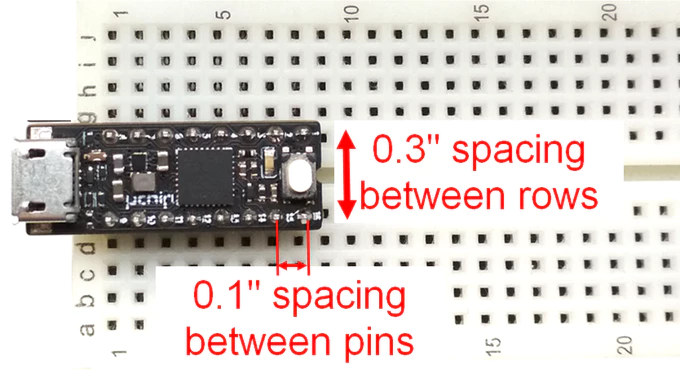
Most so-called breadboard-friendly boards that can easily be inserted into a breadboard often leave only one or two rows to play with on each side. This may suitable in many cases, but some people really want to use as many rows as possible, and come up with a solution using 90 degrees headers with 0.3″ spacing between them, just like 0.3″ wide chips do, and allowing the use of 4 rows on each side of the board. It does the trick, but this is not a standard solution, requires some bending of the headers, and covers part of the board so it’s not really ideal.
A better way would be for somebody to design a narrow board using headers with 0.3″ spacing, and that’s exactly what Itaca Innovation has done with their Arduino Zero compatible uChip board designed in a 16-pin DIP package.
uChip specifications:
- MCU – Microchip SAMD21 Arm Cortex M0+ MCU clocked @ 48 MHz (Arduino Zero Compatible) with 256 KB flash (248 KB free due to integrated bootloader), 32KB RAM with zero wait states.
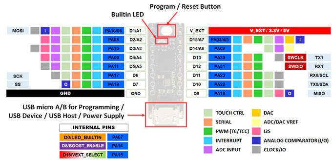
- I/Os via 2x 8-pin headers with 2.54mm pitch, 0.3″ (7.62 mm) row spacing
- 14x I/O pins including two that can be used to connect an external SWD programmer/debugger
- 7x 12-bit ADC inputs.
- 10-bit DAC output.
- 14x external interrupt input pins.
- Up to 5x serials between SPI, I2C and UART.
- I2S port for audio decoders such as UDA1334A.
- Up to 13x PWM pins.
- 2x power pins (VCC and GND)
- 14x I/O pins including two that can be used to connect an external SWD programmer/debugger
- Misc – Programmable Status LED, multi function push button for reset/program.
- Power Supply
- 5V via micro USB port, or 3.3V to 5V via pin
- Integrated 500-mA boost and 1-A buck converters and automatic power switching circuitry.
- Dimensions – 28.5 mm x 10.16 mm including USB port protrusions (4-layer board).
Each converter can also be individually turned off, so for instance, you could force power draw exclusively from external pins, or turn off an external USB device connected with a micro A cable. When powered through the USB port (5V input), the output voltage on the power pins can be selected via software to be either 3.3V or the USB voltage.
uChip can be programmed like an Arduino Zero board, but the company also developed uChip-specific libraries, which handle power supply management, a better USB host support and VGA output. Everything will be open sourced including code samples, the schematics, and Gerber files.

The board has just launched on Kickstarter with a 21,000 Euros funding target. Perks start at 20 Euros for one board, but they also offer bundles with up to 10 boards for a unit cost of 13.6 Euros. Shipping adds 1 or 2 Euros to the total cost, and delivery is scheduled for October 2019.

Jean-Luc started CNX Software in 2010 as a part-time endeavor, before quitting his job as a software engineering manager, and starting to write daily news, and reviews full time later in 2011.
Support CNX Software! Donate via cryptocurrencies, become a Patron on Patreon, or purchase goods on Amazon or Aliexpress. We also use affiliate links in articles to earn commissions if you make a purchase after clicking on those links.

The software support better be amazing because 13 euro for a microcontroller is insane.
PCBA would be about 6-7 dollars, and those who actually use this board may not have the expertise/time to build it, so it’s actually not that bad…
>PCBA would be about 6-7 dollars,
That seems expensive for a single IC and 20 or so passives. The quotes I got for board about twice that size with 3 ICs (QFN88, QFN24 and WSON8) + 40 0603 passives was $4 each for a run of 100.
Actually there are about 60 parts (top + bottom side), including inductors, emi filters, esd diodes, BJT, power mosfet, and three voltage regulators (one LDO + 2 switching regulators), . Packages include QFN, DFN and CSP…
Where did you get a $4 quote for only 100 pieces? That seems unsane!
>Actually there are about 60 parts
Is most of that on the other side of the board? I guess it gets expensive if you have a double sided load. :/
>Where did you get a $4 quote for only 100 pieces? That seems unsane!
A generic China PCB shop that I got an introduction to from a dodgy parts dealer guy in Shenzhen.. 😉 You can get similar quotes from the PCBA calculator from https://pcbshopper.com/ though.
Looks like Allpcb will do one sided load, 60 parts, 4 of which are fine pitch and QFN for $3 each in a batch of 100.
Yes, if you look at the kickstarter page, at the end of the page there is a flipped uChip, and you can see that there are many parts!
The problem is not only the assembly, but the BOM cost too (we will use full-turnkey). The BOM is expensive, unless you get to very huge numbers (at 1k it’s still quite high).
Another problem is the presence of through hole pins close to SMD parts (that’s why other boards have rows spaced at least 0.4″ or even more). You can’t use wave solder, and even for selective wave soldering you need a shield to protect top SMD components.
That makes sense. I hope there is enough people that fit your niche (breadboard-able) to meet your goal. I think it’s going to be a hard sell though with all of the little STM32, ESP etc thingies out there.
I put together a board that’s the same size as the STM32 blue pill boards but has a 1ghz cortex a7 on it. The BOM cost is ~$7 and the PCBA is the $4 I mentioned above. I considered making 100 and sticking it on kickstarter or similar but with $7 ESP32s out there I didn’t think I’d be able to price it high enough to actually make it worth doing.
1GHz Cortex A7? That’s impressive! How much RAM/FLASH memory? Have you already a kickstarter preview campaign link?
Not sure what will be the final price (shipping is another big hassle…), but I think that you can manage to reach your goal! One can’t compare a Cortex A7 board with an ESP32 or even worse 2$ ESP12F (not to mention ST32x). These are meant for completely different purposes.
64MB of DDR2 in the package and 16MB of SPI NOR flash externally connected.
The chip is in a 80 pin QFN so in theory you can solder it at home with a hot air rework station.
I was thinking $15 but shipping etc is a massive pain and it’s especially expensive from here.
>One can’t compare a Cortex A7 board with an ESP32
This one has SPI, I2C, 4 ADC channels etc so it’s got all of the micro controller bits you would want. It also has a deep sleep mode where you can turn off everything except an 8051 that’s also in there. The 8051 can then trigger the cortex a7 to boot back up from a gpio, rtc or ethernet event.
Very impressive, so it will be able to run some small footprint linux OS! Unlike cheap ST32 and ESP boards, so definitely, looking only at the price (without considering the huge difference) would be an unfair comparison!
Yes, shipping cost is very high. Furthermore one must also take into account defective parts and lost/damaged packets (even if we use tracked shipping, some “magic” always can occur… ) :/
Where are you based from?
The chip isn’t supported in upstream Linux but I ported the mainline kernel and wrote drivers for the flash, gpio, interrupt controller etc so far. Ethernet already works.. just USB, SDIO to go before it’s fully usable. Standard python runs pretty well so if I can get it running as a USB gadget it should be possible to just copy a python script to it and have it run it automatically. If I get the SDIO working you could add an ampak wifi module for a few $ and have something like an ESP32 on acid. There’s a camera interface, H264 encoder etc in the chip but it’ll likely be impossible to write drivers for those.
Returns, complaints, shipping fails. I think a lot of kickstarters end up making a loss because of issues like that. I’m thinking of crowdsupply too but it might not be worth the effort either.
I’m based in the middle of nowhere in Japan. Registered shipping would be $2 minimum I think.
For reference this is how small this thing is https://imgur.com/a/46qYdNo
The two other chips are Allwinner V3S and S3 which are similar Cortex A7 with memory chips. This guy is cheaper ($3.8 is the best so far), not BGA and tiny. 🙂
Article about the chip. No link to the datasheet, though.
https://www.unifore.net/ip-video-surveillance/mstar-msc313e-msc316dm-msc318-ip-camera-soc-datasheet-sdk.html
>Article about the chip. No link to the datasheet, though.
I have the data briefs, the SDK and can point you to sources to get the chips if you’re interested.
Yes, please. Hit me up on freenode IRC. My username is my last name.
You thinking of the Allwinner S3/V3 type parts? (edited) Oh, wait, saw the 8051 part. That’s not Allwinner, then. They use an or12K supervisor….
>You thinking of the Allwinner S3/V3 type parts
I have done a SoM based on the S3 and the V3. The V3 is QFP which is easier to hand solder but it’s massive in the scheme of things. Also it only has one usable SPI interface. Once you put SPI NOR on that for booting you don’t really have SPI anymore.
I really want something that’s not much bigger than an arduino nano and is cheap enough that you can solder it down to a project and forget about it. I tried the S3 because it’s smaller but if you mess up soldering a BGA you basically have to throw it away ($4 chip isn’t worth reballing). Also it was really hard getting the S3s. I was looking at putting down a few thousand dollars to get them at a good price.
I’m impressed if you can keep the costs at 15$ (even $20 would be a good price for that beast), considering also the 5+4% kickstarter/stripe fees and the safety margin (if you are based in Japan, then I guess your campaign won’t be in USD so you should take into account possible USD/YEN fluctuations).
Please remind me when your project goes live!
I came not expecting to be impressed, but I like this design. I think they went a bit too far with the dual voltage for V_IO which cost them an additional SMPS, but the rest of it looks great.
You guys interested in making a rotated board like I proposed in the comment this article starts out talking about? It’d be way cheaper. 🙂
Yes, it might be cheaper but taller too! Still that solution is neat too!
It’s way cheaper as you can use the same board fab as the existing blue pill boards–no four layer needed, two sides to put parts on.
The height could be an issue, but it’s not *that* tall that you can’t get a jumper over it comfortably. And, if done right, you could use the top of the board as a pin label–which the design in this article is missing. It’s a reasonable tradeoff to make, I’m not criticizing it, but it’s a missing feature. (maybe put a sticker over the top….)
Maybe a stupid idea: I was wondering if there is such a big difference in price for production of 2 layer PCB vs 4 layer PCB and dual side soldering, whether a ‘sandwiched’ board could be made out of 2 regular two layer boards (single side soldering, one side on each board). Lets’ say use two 0.8″ thick boards (on a hobby type production Chinese fabs/sites sold for 5$, vs 49$ for 4 layer PCB) , put them on top of each other and then use through hole soldering to fix them together and also connect the vias (through hole). Apart form extra complexity (which of course would costs extra) would it 1) make electrically comparable board to a genuine 4 layer board, and 2) be cheaper in the end?
I don’t think that would end up any cheaper. With the small run PCB companies ten 2 layer boards are about a quarter or less of the price of ten 4 layer boards ($1 instead of $4 for 100mm x 100mm) but once you order 100 or more the price of each 4 layer drops a lot (to $1.2 for 100mm x 100mm). It’s probably because the initial setup costs are loaded into board cost now. The setup cost doesn’t change if you order 1 or 1000. On the other hand any manual process you add into the assembly will cost you a fixed amount per board. At $DAYJOB the figure I heard is that one minute of extra production time adds $1 to the assembly cost. That’s for a US factory though so maybe it’d be cheaper in China but it’s still a fixed cost being added to every board.
I hadn’t seen that comment you’re referring to before, very nice! I think you might be interested in what Texas Instruments did with some of their Launchpad boards: http://processors.wiki.ti.com/index.php/CLP_Breadboard
IIRC, you mentioned that last time and I agreed that’s the way to do it. I just want to do it for the STM32F103 chip which is substantially cheaper than the TI chips. 🙂
While this Kickstarter campaign did not reach its goal it did have over 20K in pledges, pretty impressive.
Itaca went ahead and now sells this device on their website
https://shop.itaca-innovation.com/
But you do have another opportunity to get this through Kickstarter. We are bundling this device with our BASIC compiler for ARMs.
https://www.kickstarter.com/projects/703885653/basic-compiler-for-arduino-zero-boards
So glad to hear that! Thanks for the update!
wow. you could make powerful devices with this in the form factor of a pen. so cool.