
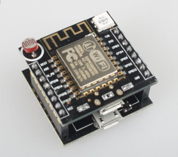
In case you need a cheap and compact ESP8266 board with integrated USB to TTL debug interface, a photo resistor, and/or some buttons, a white brand board based on ESP-12F could be interesting.
 “Witty cloud” development board specifications:
- ESP-12F module with Espressif ESP8266EX SoC
- Connectivity – WiFi 802.11 b/g/n
- 2x 8-pin headers with GPIOs, VCC, GND, Reset, ADC, and UART
- USB – 2x micro USB port (one for power, one for debugging ?)
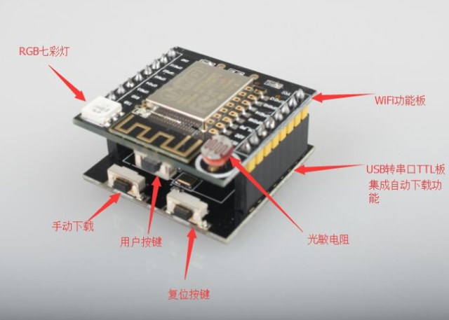
- Misc – Photo resistor, RGB LED, three buttons for power, reset and firmware upgrade (I think)
- Dimensions – Small
 Witty cloud might not be the same of the board itself, but could be a cloud service launched in China, as some of the screenshot on Aliexpress could imply. All I could find are some websites vaguely mentioning GoKit 3.0 and Witty Cloud 3.0, but it does not make much sense. If Chinese readers could provide some insights here it would be nice.

The board sells for as low as $3 + shipping on Aliexpress, which amounts to $4.85 in total in my case.
Via Pete Scargill

Jean-Luc started CNX Software in 2010 as a part-time endeavor, before quitting his job as a software engineering manager, and starting to write daily news, and reviews full time later in 2011.
Support CNX Software! Donate via cryptocurrencies, become a Patron on Patreon, or purchase goods on Amazon or Aliexpress. We also use affiliate links in articles to earn commissions if you make a purchase after clicking on those links.


Finally some price going down. I mean those cp2102 usb dongles adaptors sell for 1EUR, and adding an esp8266 should not make the price climb to 10EUR, like it is the case for some nodemcu boards. With some minimal soldering, you could make your own adaptor for ESP01: http://www.zoobab.com/cp2102-esp8266. I still have to make improvements, but you get the idea.
“Witty cloud” is the name of the cloud service, but seems like they may be deliberately naming it that way to differentiate the board from other ESP8266 boards.
This board looks rather similar to Oak by Digistump, funded on kickstarter some 6 months back, and which you’ve also covered on this blog. Both are manufactured by AI-Thinker, and similarly based on ESP-12. The Oak will come with 4MB flash memory, there’s no indication what amount this board will come with. Finally, Oak (not shipping yet) will be using Particle cloud, so I guess they’re trying to do something similar using “witty cloud”.
http://www.aliexpress.com/item/ESP8266-serial-WIFI-Witty-cloud-Development-Board-ESP-12F-module-MINI-nodemcu/32566502491.html
$2.94US with free shipping to Canada, if you buy 1 or 2, so I bought 3 on two separate orders.
Looks like once you flash/program the chip, you dont need to keep the bottom half during production.
Now if only I could plug this into an opto-coupler relay board and 120volts AC to 3.3v DC regulator, I’m a happy camper!
@sk
Thanks!
@J0539h
$2.94 shipped is really amazing… That link still has a $1.85 shipping fee for me though.
i did a quick check on taobao
found their site
http://www.gizwits.com/
looks like a legit iot device manufacturer
scroll down their main page you’ll see their boards
also their forum
http://club.gizwits.com/forum.php
its in chinese,
what do you want to know?
i can read & write in Chinese.
@milkboy
Thanks! I just wanted to find out what Witty Cloud was exactly, and where it could be found. So I guess everything must be handled by gizwits.
They support quite a few others boards apart from that ESP8266 board… including some I’ve never heard of…
1. TinyCon2005-a – http://www.ralinwi.com/product.aspx?info_lb=54&flag=1
2. Nufront NL6621 – http://www.nufrontsoft.com/index.php/project/index/id/16.html. Some source on Github for Yeelink lightbulbs -> https://github.com/NufrontIOT/NL6621-Yeelink?from=codefrom.com
3. HFLPB100 -> http://www.hi-flying.com/products_detail/&productId=68f4fd7b-39f8-4995-93ab-53193ac5cf22.html
4. G510-Q50-00 -> http://www.fibocom.com/product/2-1-2-1.html
5. IOE65 -> Update of IEO20 http://www.ittim.cn/products.php?pid=5 . Company name: I think therefore I am 🙂
All Chinese companies and Espressif’s competitors. I wonder if any of these are news worthy. Quite tough to find much info without reading Chinese.
there is also a new version of esp coming up, it has bluetooth support as well.
also while looking tru taobao, i discovered another board
http://tisan.pandocloud.com/about
and Black board T5
https://item.taobao.com/item.htm?spm=a230r.1.14.8.ZYLQbD&id=520973632406&ns=1&abbucket=20#detail
lemme know if you cant open the link,cos its is a local taobao. so if there is a chance you wont be able to see it if dont access it with a china ip address.
@suvir
A friend told me you could achieve similar networking speeds over Bluetooth then wifi, I was sceptical.
@zoobab
I thought Bluetooth 3.0 and greater could use the WiFi link to transfer data at higher speeds -> http://www.cnx-software.com/2013/06/05/bluetooth-versions-walkthrough-and-bluetooth-4-0-low-energy-development-resources/
It’s optional though, and I guess it’s not enabled in my phone, and transfer pictures over Bluetooth is always very slow for me.
@J0539h
I think, you don’t need 3.3V power source in case of existing USB connector. It’s LM1117 5v->3.3V regulator on it’s back side, so you can use micro-usb (5V) to power this.
See this: http://www.aliexpress.com/item/ESP8266-serial-WIFI-Witty-cloud-Development-Board-ESP-12F-module-MINI-nodemcu/32566502491.html?spm=2114.10010108.0.115.wdpe3b
Hi
Does someone has documentation for that ? Vcc is 3.3 or 5v? What are the mappings of gpio ?
Thanks
@milkboy
Interesting.
BBT5 sells for $6 shipped on AliExpress, 30Yuan on TaoBao. From the photos, it has DHT11, CP1202 USB/TTL, 3 RGB LEDs and relay, plus buzzer. It uses the newer ESP-13 (AKA ESP Wroom-2) form factor module. If you need all the sensors and relay, it’s a very good deal, assembling it from parts will cost you much more (DHT11 itself is $1).
TiSan is more expensive ($14> on Ali-X), seems to have about same sensors, but larger PCB (uses ESP-12E), and CH340G USB/TTL (doesn’t matter much).
Greg
Just received mines today. They are really great for the price, I will try the esp-link firmware on those.
The only minor point is that you have to unplug the USB board to make it breaboard friendly. I am working on a small hack to solve that.
@Greg Ware
The Black Board is useless, unless you are making a living out of programming 8051.
https://esp8266hints.wordpress.com/2015/10/25/nuther-new-something-in-town-you-can-safely-ignore-it/
https://esp8266hints.wordpress.com/2015/12/07/reworking-the-ai-thinker-t5-board/
@cnxsoft
Interesting list. Things are really happening out of China nowadays, not Silicon Valley…
I don’t think any of these will fly in the western market though, although the chinese market could be enough to sustain them.
Espressif has been one of the first on that market, with a very low price point, and somehow they relased some material in English (by pure chance I think), which allowed the community to start and since then has been key to ESP’s success. Espressif owes a lot to Noce-MCU folks and the community.
IMHO, there is not enough bandwidth in the community for this to happen again, unless another compelling system comes out (i.e. ARM-based, dirt-cheap, wifi+BLE+GPS+GPRS, ADCs, …) that would make ESP8266 obsolete. If ESP-32 can be kept cheap enough, given Espressif’s openess towards the existing community, it could work out.
Greg
@Beobachter
Well, a bit extreme I’d say. AI Thinkers probably has good reasons to produce this board (and the ESP-14 for that matter), you cannot dismiss those behind the ESP-xx range of boards, they are not idiots at all. They probably have other markets in mind that mere hobbysists, although I have a hard time figuring out which…
If they were interested in the hobbyist market only, they would have produced only one board with 1/10″ pins a la NodeMCU, not a full range of integratable boards.
Greg
@Greg Ware
Well, sure, that’s why I had the “unless” in my comment…
There is nothing wrong with the basic concept of the BBT5: If you want to run a battery-operated application, it is actually a very good idea to put an ESP8266 under “adult supervision” (completely removing its power when you don’t need the power-hungry WiFi). It’s just that having an 8051 as that supervising adult is not generally very useful in 2016; in this case it is exacerbated by the fact that all those nice transducers are connected to the 8051 and not the ESP8266. So ESP8266 hackers can do exactly nothing with this board until they whip out the soldering iron.
@Beobachter
Well, okay, it is weird for an architecture. Same goes for ESP-14.
I would go with trying to reflash the ESP and use the other mcu just for I/O.
It seems that gizwits has a model of driving their boards from Wifi directly somehow, through some bespoke ESP firmware, as for this ESP Witty Board (see posts on http://www.esp8266.com about this).
Another thing I’m wondering is why they sell both boards (USB+main) together.
Once you have one or two USB/TTL underboards, you don’t need more, the main board would be enough.
Now its 2.80 with free shipping, I wonder if he is alternating with the shipping charges.
You would think you could simply connect to the lower board and run ESPLORER, But that doesn’t work.
I tried Arduino IDE with it and it works great!
RGB LED:
GPIO15=red
GPIO12=green
GPIO13=blue
@sun2steam thanks for the info I was looking howto control the rgb led…
This makes a RED led blink:
// the setup function runs once when you press reset or power the board
void setup() {
// initialize digital pin 15 as an output.
pinMode(15, OUTPUT);
}
// the loop function runs over and over again forever
void loop() {
digitalWrite(15, HIGH); // turn the LED on (HIGH is the voltage level)
delay(1000); // wait for a second
digitalWrite(15, LOW); // turn the LED off by making the voltage LOW
delay(1000); // wait for a second
}
This uses RGB LED as output for ambient light sensor.
——————————————————————————–
/*
Analog input, analog output, serial output
Reads an analog input pin, maps the result to a range from 0 to 255
and uses the result to set the pulsewidth modulation (PWM) of an output pin.
Also prints the results to the serial monitor.
The circuit:
* potentiometer connected to analog pin 0.
Center pin of the potentiometer goes to the analog pin.
side pins of the potentiometer go to +5V and ground
* LED connected from digital pin 9 to ground
created 29 Dec. 2008
modified 9 Apr 2012
by Tom Igoe
This example code is in the public domain.
Modified by Jo Muller to run on the nodemcu from ‘Witty cloud’ using optical sensor as input instead of potentiometer and using built in RGB LED as output.
All 3 colours are possible as the blue LED is used to give a signal on change of light.
1 Feb, 2016
*/
// These constants won’t change. They’re used to give names
// to the pins used:
const int analogInPin = A0; // Analog input pin that the potentiometer is attached to
const int analogOutPinGREEN = 12; // Analog output pin that the LED is attached to
const int analogOutPinBLUE = 13; // Analog output pin that the LED is attached to
const int analogOutPinRED = 15; // Analog output pin that the LED is attached to
int sensorValue = 0; // value read from the pot
int outputValue = 0; // value output to the PWM (analog out)
int lastValue =0;
void setup() {
// initialize serial communications
Serial.begin(115200);
}
void loop() {
// read the analog in value:
sensorValue = analogRead(analogInPin);
// map it to the range of the analog out:
sensorValue=constrain(sensorValue,200,700);
outputValue = map(sensorValue, 200, 700, 0, 255);
// change the analog out value:
analogWrite(analogOutPinRED, outputValue);
analogWrite(analogOutPinGREEN, 255-outputValue);
analogWrite(analogOutPinBLUE, lastValue-outputValue);
// print the results to the serial monitor:
Serial.print(“sensor = ” );
Serial.print(sensorValue);
Serial.print(“\t output = “);
Serial.println(outputValue);
// wait 2 milliseconds before the next loop
// for the analog-to-digital converter to settle
// after the last reading:
lastValue=outputValue;
delay(2);
}
Does anybody know what the upper push button is for?
@Sun2steam: the push button below the antenna is mapped to GPIO 4, and reports either 0 or 1 (0 when pushed)
@Sun2steam
The upper push button appears to be connected to GPIO4 and GND.
There also is a 10k pullup from GPIO4 to VCC.
So it seems to me that this is a button that can serve an application function:
button not pressed ➔ GPIO4 = high, button pressed ➔ GPIO4 = low.
Hi
I have read that the LDR is connected to the ADC (A0). Has anyone been able to use the ADC for something else? @Sun2steam you seem to have successfully read your potentiometer from A0. Did you have to do something special to ensure this is not the onboard LDR?
Thanks
Lee.
$6 on DX:
http://www.dx.com/p/esp-12f-iot-2-4g-wi-fi-wireless-development-board-module-w-antenna-ch340g-driver-black-white-425111#.VsrcpD-vEu5
Couldn’t find kits with baseboard on Ebay except this huge one:
http://www.ebay.com/itm/ESP8266-ESP-12F-Test-Board-Serial-WIFI-Module-Module-Coexistence-Module-New-/172029410661
How do you we get Micropython to work on this? :p
Ordered 2, coming on the way from China to India.
Can someone confirm whether it works with 5v Micro USB port, strange to find it support 3.3 v, I like to use these boards like no-brainer as I do with other NodeMCUs.
Any one tried connecting Witty with Micro USB direct computer ie 5V?
I found it at Gearbest, 4$ free shipping :
http://www.gearbest.com/boards-shields/pp_315640.html