
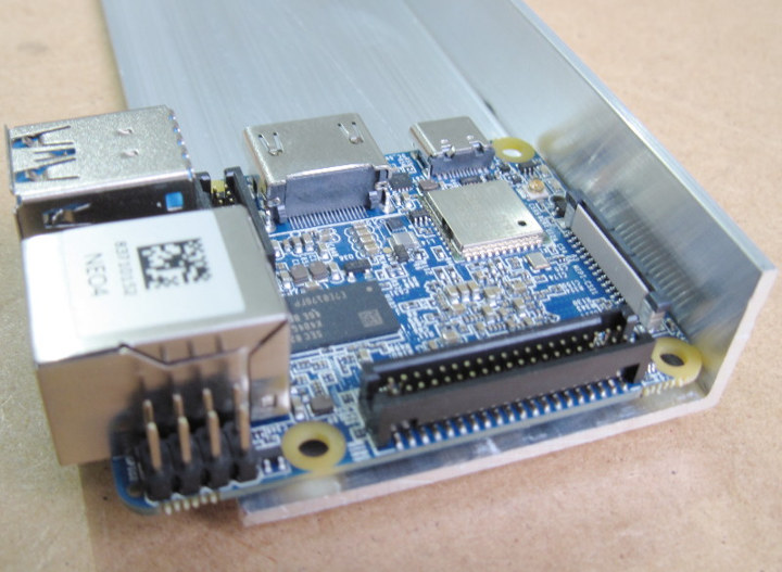
FriendlyElec NanoPi NEO4 is currently the cheapest and smallest SBC powered by Rockchip RK3399 hexa-core processor which packs two Cortex A72 “fast” 64-bit cores, and four Cortex-A53 “efficiency” cores, so it should be an obvious candidate if you plan on building an Arm build farm costs to its low cost, small form factor, and relatively good performance.
As part of his work on HAProxy load balancer, Willy Tarreau often has to run time-consuming builds for Arm targets, and to speed up the builds he’s put together several Arm based build farms powered by low cost development boards / SBCs. Up to now he had a build farm powered by five MIQI boards featuring Rockchip RK3288 processor with four Cortex-A17 “fast” 32-bit processor, and controlled with a ClearFog Pro networking board. He’s now decided to build another similar build farm but with NanoPi NEO4 boards instead.
Willy goes through the hardware setup, and software into much details in a blog post, so I’ll try to give a summary highlighting the key points in this article.
Hardware Build and DIY Heatsink
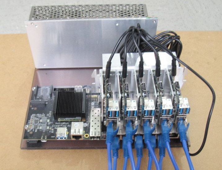
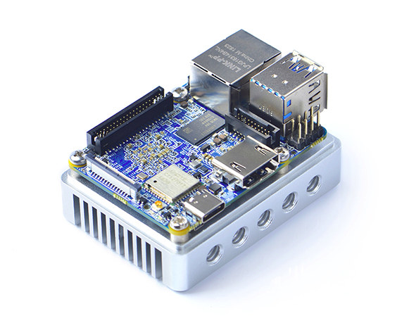
As you can see from the photo above, the setup comes with five NanoPi NEO4 boards connected to ClearFog Pro board over a Gigabit Ethernet connection. But there’s something funny about the heatsink, it does not look like the heatsink provided by FriendlyElec at all… Willy wanted to save some horizontal space, so instead he made his own heatsinks out of an L-shaped aluminum block that 5.2cm wide and comes with a 2mm thick aluminum corner.
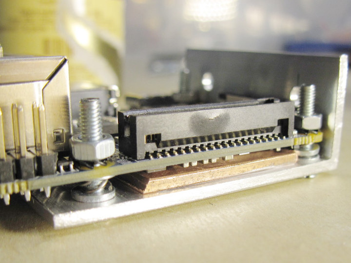
He drilled four mounting holes into the aluminum block, and added a ceramic pad for cooling the processor at first, but eventually switched to copper pads coupled with screws and spring to kept the processor, pad and aluminum block in good contact without too much force applied.
Once all five boards are prepared in a similar fashion, we’re still not finished with the five boards themselves connected to a much larger heatsink taken from an old Pentium2 system using a large band of thermal tape since going with screws was not practical.
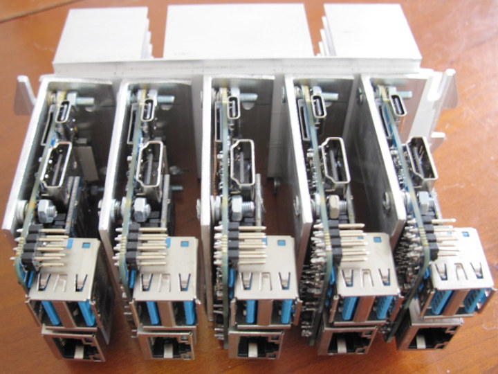
That part was fun, and I could even have published a separate post just about the DIY heatsink. The hardware build needs to be completed USB-C cables and a 5-port USB power supply such as this one.
Software Installation, and Optimization (Overclocking)
The default FriendlyElec Ubuntu images were installed to eMMC flash module, and Willy disabled “systemd related crap”, as well as graphics mode since it’s needed for the use case. An important tip during installation is not to duplicate the flash from one board to install on the others, as it will also replace the MAC address, and you obviously don’t want 5 boards with the same MAC address in your local network 🙂
Since that’s a build farm for C programs, distcc was installed as well as various compilers from kernel.org.
In order to get the most performance of the board he overclocked them with the Cortex-A72 cores reaching up to 2.2 GHz, and Cortex-A53 cores up to 1.8 GHz, except for one were it had to be limited to 1.7 GHz, so finally all boards for their LITTLE cores limited to 1.7 GHz for practical reasons. The overclocking requires some kernel patches for linux 4.4.138 and a script to change the frequencies:
|
1 2 3 4 5 6 7 8 9 |
# cat set-speed-neo4-1.sh echo 2 > /sys/kernel/debug/clk/sclk_ddrc/clk_enable_count echo 928000000 > /sys/kernel/debug/clk/sclk_ddrc/clk_rate echo 1 > /sys/devices/system/cpu/cpufreq/boost echo 1704000 > /sys/devices/system/cpu/cpufreq/policy0/scaling_max_freq echo 2208000 > /sys/devices/system/cpu/cpufreq/policy4/scaling_max_freq echo performance > /sys/devices/system/cpu/cpufreq/policy0/scaling_governor echo performance > /sys/devices/system/cpu/cpufreq/policy4/scaling_governor echo performance > /sys/devices/platform/dmc/devfreq/dmc/governor |
Final words
Some improvements are also discussed, such as replacing the overpowered ClearFog Pro board with a NanoPi NEO2 and an 8-port Gigabit Ethernet switch, as well as adding a reset button to the board to facilitate debugging.
Willy concludes as follows:
This constitutes a nice upgrade to the previous farm and I feel more confident hacking a bit with it thanks to the removable eMMC that I can easily re-flash from my PC. The boards are easy to hack on since all sources and docs are available, which is a real joy.

Jean-Luc started CNX Software in 2010 as a part-time endeavor, before quitting his job as a software engineering manager, and starting to write daily news, and reviews full time later in 2011.
Support CNX Software! Donate via cryptocurrencies, become a Patron on Patreon, or purchase goods on Amazon or Aliexpress. We also use affiliate links in articles to earn commissions if you make a purchase after clicking on those links.


> as well as adding a reset button to the board to facilitate debugging.
I have an Allwinner v3s board that would probably be good for something like this.
The v3s has 8 uarts and 8 load switches connected to it and you can control it over mqtt to bring up machines on demand/trigger reboots. Potentially it could interact with u-boot on the boards to do flashing via tftp.
This could indeed be an option. Over time I also found that using USB hubs with cheap USB UARTs is nice as well. When you see the cheap CH340G and its SOP8 successor whose I already forgot the name, it’s trivial to connect them to any device in fact. I haven’t worked on this part yet, for now I don’t need the reset that much.
How is the cooling doing Willy?
Do these help?
https://www.simscale.com/blog/2016/10/key-factors-heat-sink-design/
https://www.fictiv.com/hwg/design/heat-sink-design-guide
http://www.ppi-uk.com/news/what-makes-a-good-heat-sink/
Might give some thoughts
Not much in fact, the two first ones are related to internal heat sinks, and the last one provides medium-sized ones. I’m interested in having a huge one sharing the heat between all devices. I have a much better design in mind, I’ll draw it soon. In short it would consist in using the L-shaped alu blocks to conduct the heat towards a thick bottom plate, on which a rear large heatsink would be installed. This would remove all the thermal tape and allow for screws to be used for more efficient contact.
True, but to thick a thermal tape can hinder heat transfer, also having the main heat sink away from the heat source hinders heat transfer. That is why some GPU use heat pipes to transfer heat. A low voltage sub 3V fan and a cone cylinder pipe,,with a cowl to pull air through would work fine, oh well.
This quick-n-ugly drawing shows how I’m seeing it :
http://1wt.eu/nanopi4/neo4-cooling.png
It should even shorten the distance between the CPU and the big heat sink, and using a thick plate it will reduce the resistance. Also the benefit is that the plate will also help spread some of the heat into the support (table or whatever lies under it).
Since the 4 holes represent an exact square, I can turn the L-shaped block 90 degrees and try this once I find the plate I need 😉
After I did some tests a while ago for me I came to the conclusion to rely on a heatsink solution with as less own thermal mass as possible and with as large heatsink finks with sufficient spacing in between (later operated vertically so convection can help): https://github.com/ThomasKaiser/Knowledge/blob/master/articles/Heatsink_Efficiency.md
For five NEO4 I would probably end up with five copper shims (20x20x1mm) and then order on Aliexpress ‘245mm+60mm+25mm full aluminum E Heatsink for Power amplifier’. All NEO4 would be mounted next to it other directly to the heatsink using the copper shims and two thin films of thermal compound in between. Powering then through the 4 pin header of course and eMMC needed since SD card slot being blocked on 4 boards.
tkaiser, if you can get hands on a defect psu there are plenty of heatsinks inside. No need to buy one on aliexpress.
That’s approximately the type of heatsink I have for the MiQi farm. And yes, spacing is important for passive convection. Picking a dense heatsink designed for a CPU with an active fan gives horrible results. For compactness, I really want to mount the boards vertically. I thought about mounting them horizontally on a large heat sink as you suggest but that would have been too large for me (it’s a matter of taste).
I think you are asking a lot for the heat transfer, heat likes going up in warm air, and the base and the back will both be heat sources, I suspect causing heat spots.
Did you measure any temperatures with your existing arrangement, either assembled or in pieces?
You said you did a cpu burn test before attaching things to the big heatsink and it was “OK.” What constitutes “OK?”
It seems like you aren’t going to get enough of a thermal gradient between the big heatspreader and the heatsink to move much power through that 2mm cross-section of aluminum.
> Did you measure any temperatures with your existing arrangement, either assembled or in pieces?
Yes, with cpuburn it stabilizes around 86 degrees. But it’s not very hot in the room, which is why I’d like to improve the design to better stand summer.
I ordered a thermal camera 3 months ago for this but it still didn’t arrive 🙁
> What constitutes “OK?”
not throttling for a while, and making sure the L-shaped plate are as hot as the
rest of the mainboard, indicating the contact between the CPU and the plate is good.
> you aren’t going to get enough of a thermal gradient between the big heatspreader and the heatsink to move much power through that 2mm cross-section of aluminum.
This is part of the reason why I used a thick copper plate in parallel to the aluminum one. Copper is almost half resistive as aluminum, thus 2mm copper + 2mm alu almost perform like 5-6mm aluminum.
A thick L-shaped copper plate would probably be awesome but would be a pain to cut!
I still suspect you will get slower air pockets between each SBC causing a warm blanket effect.
Water flows through pipes but heat radiates, so needs a push or pull for maximum cooling effect. IMO
Willy,
where did you get the springs to put over the bolts? I did a similar design some while ago (just for one board), and used some springs from a heatsink from a old graphics card. Now I won to do a similar design for another board, but I don’t have donor material anymore.
I took similar springs, that I had to cut because 1) I didn’t have enough of them, and 2) even once compressed they were too thick. So I cut them in 3 to have around 3 turns each at most. I really don’t like my design there but the alternative was to use 4.5 washers per hole and I didn’t have enough either, and this .5 was becoming problematic to make 🙂
I also thought about using some 3-4mm heat shrink tube to replace springs. I think it can work as it will resist compression quite a bit.
Yes, maybe a piece of rubber tube should do also. Good idea!
As already asked over there https://www.cnx-software.com/2018/10/10/nanopi-neo4-cheapest-smallest-rk3399-board/#comment-559659 I would be really interested in knowing results with mainline kernel (due to higher memory performance) and a quick 7-zip benchmark comparison between the MiQi and the NEO4 cluster.
Not tested yet! Too many questions start to flood back here at the same time 🙂
OK, here it comes :
# 7z b
7-Zip [64] 16.02 : Copyright (c) 1999-2016 Igor Pavlov : 2016-05-21
p7zip Version 16.02 (locale=en_US,Utf16=on,HugeFiles=on,64 bits,6 CPUs LE)
LE
CPU Freq: 2200 2202 2201 2202 2201 2202 2201 2202 2202
RAM size: 967 MB, # CPU hardware threads: 6
RAM usage: 675 MB, # Benchmark threads: 6
Compressing | Decompressing
Dict Speed Usage R/U Rating | Speed Usage R/U Rating
KiB/s % MIPS MIPS | KiB/s % MIPS MIPS
22: 5142 503 994 5002 | 111592 518 1835 9517
23: 4761 509 953 4851 | 109394 521 1816 9466
24: 4482 513 939 4819 | 106414 521 1792 9340
———————————- | ——————————
Avr: 509 962 4891 | 520 1814 9441
Tot: 514 1388 7166
I don’t know how that compares to other machines you know.
RK3288 (Tinkerboard running with 4.14) and ‘conservative’ settings scores ~5350: (the 1.8 GHz cpufreq OPP results in just 1730 MHz confirmed by your mhz tool, no idea about DRAM controller settings) while a NEO4 with slight overclock (2.0/1.5 GHz) scores between 6750 (4.19) and 6500 (4.4). Results (details in most right column): https://github.com/ThomasKaiser/sbc-bench/blob/master/Results.md
Would be interesting to get a 7-zip score also from one of your tuned MiQi’s 🙂 I would expect something slightly above 6000 (would then be in sync with your compile time differences comparing MiQi and NEO4 cluster).
Hmmm quite interesting 🙂 I definitely need to test on 4.19 then. I’ll use my M4 which is spare now for this, it will be easier than hacking in the farm. In the past the rockchip blobs used to provide much higher DDR performance but this might have changed. Regarding the test on the MiQis it will not be easy, it’s a hand-made distro, there’s not even a C++ toolchain for it so we’ll need a static 7z utility to try it.
By the way, which one is supposed to be the correct value here ? There are plenty on the Avr and Tot column. I suppose the rightmost on the Tot column ?
I would believe with preserved formatting it’s somewhat obvious 🙂
The ‘Avr:’ line lists compression/decompression separately (one depends more on memory latency, the other more on integer CPU horsepower).
First utilization in % (it’s normal on ARM that we don’t see 600% with a hexa-core CPU but just 5xx% — with Hyper-Threading on Intel it’s a different story). Then R/U –> 7-zip MIPS rating divided by utilization. And then the real MIPS rating.
Last line simply shows averaged values +/- some rounding errors. The right value is the multi-threaded score and the one in the middle an averaged single-threaded score (not that useful with big.LITTLE if we care about CPU affinity and intelligent scheduling)
The Total score is what we use to estimate roughly how a system will perform with ‘typical server tasks’…
> I would believe with preserved formatting it’s somewhat obvious
I have absolutely no idea how to present the output like you do!
Anyway thanks for the explanation, now I see where you took the numbers and next time I can give you just the number you need 😉
You can use WordPress preformatted tag as explained @ https://codex.wordpress.org/Writing_Code_in_Your_Posts#Using_the_.3Cpre.3E_tag
Edit: Sorry wrong link the first time, now OK.
OK, good to know, thank you!
There’s a typo in Willy’s name …
By the way, thank you Jean-Luc for relaying this article, I really feel like it was worth writing it if people find it interesting 🙂
What issues are you having with the power supply?
AC110-220V to 5V/60A DC Switching Power Supply for LEDs is about $25. The 40A version is about $20.
The Tizen and LAVA folks use a plain ol’ ATX power supply.
with this one, none.
Cool. Looks like you’re already using the LED power supply 🙂
In your article:
> “Possible improvements”
> …
> “The power supply would still remain an issue though.”
What does this mean ?
Ah got it! Well it’s simple, in order to power this number of boards you need a *strong* power supply. The cheap USB ones whose real rating needs to be halved are often not enough to power 5 boards, hence the big 5V/30A one I purchased there. But since this one doesn’t have USB outputs, I had to make the adapter board myself. Another solution would be to use one single-port PSU per board, but it requires many mains plugs.
Yes that is troublesome. The adapter you made is neat, makes it modular.
I chose to cut the USB A ports and wire directly to the PSU outputs. This also decreased the voltage drop and let me tidy up the cables to the exact length needed.
Just noticed this :
> has to run time-consuming builds for Arm targets
In fact not even, I use this farm to build for x86_64 and run it on my laptop. Building everything in 3 seconds is quite pleasant and doesn’t make you think before running “make clean”. And for the kernel, it’s the same, I’m building x86 kernels as well. This is why I’m using cross-compilers there. I noticed that gcc 7 is almost twice as slow as was gcc 4.7, to produce code that is not always as good… Fortunately the kernel is still compatible with 4.6 and above.
OK. I wrongly assumed you want to build natively instead of cross-compiling. But instead, you are cross-compiling x86 / x86_64 code on Arm hardware. I read too fast since the cross-compilers should have made it obvious.