
Last month, I received Qoitech Otii Arc power supply, power meter, and DAQ unit that aims at helping hardware and software engineers develop energy-efficient products.
I’ve now had time to test the unit with an ESP8266 board and Raspberry Pi 4 SBC, so I’ll show how to get started and my overall experience with the hardware and program.
Requirements and Initial Setup
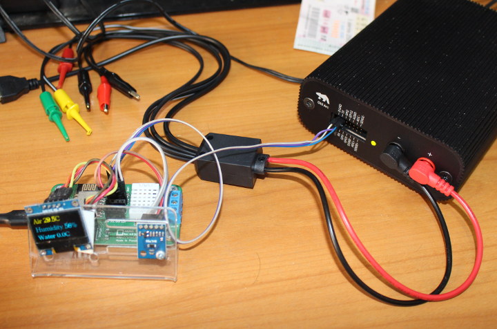
The unit takes a 9V power supply or micro USB adapter as power input, but power output is done through banana plugs. I did not have any cables with banana plugs so I bought one on eBay for about $5 shipped.
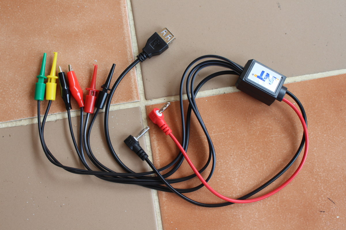
This cable is really convenient with output to USB (female connector), crocodile clips, and hook clips. However, as we’ll see below it may not be suitable for all types of loads, and you may have to make your own with a higher rated cable.
You’ll need to download Otii program available for Windows 10 / 7 64-bit, Mac OS Catalina or Mojave, and Ubuntu 18.04 or 19.04. I installed the program in a laptop running Ubuntu 18.04, but the OS mostly does not matter.
Using Qoitech Otii with ESP8266 ANAVI Thermometer board
I had to get a board to test the solution, and since ANAVI Thermometer is always on my desk acting as a dumb temperature and humidity display, I went with that one.

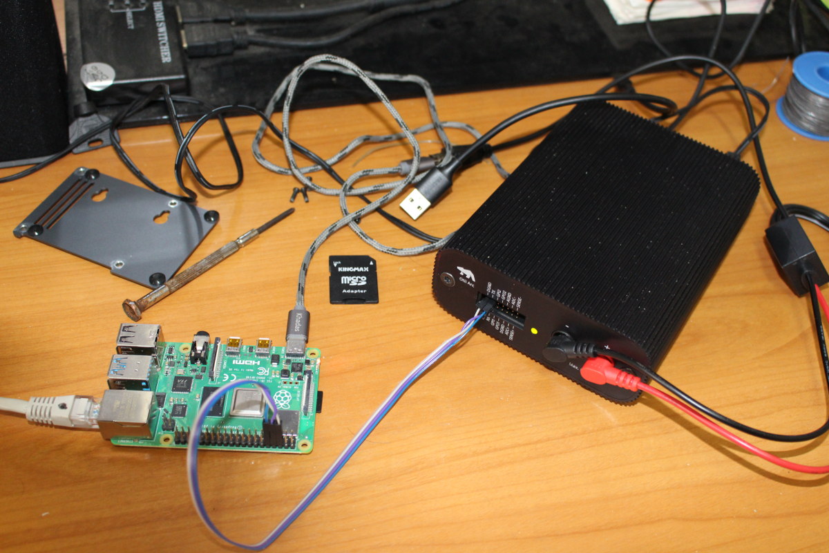
Otii Arc (that’s the name of the black box) will power the ESP8266 board via the cable I purchased plus a USB to micro USB cable, and is connected and powered via a USB 3.0 port from my Ubuntu laptop.
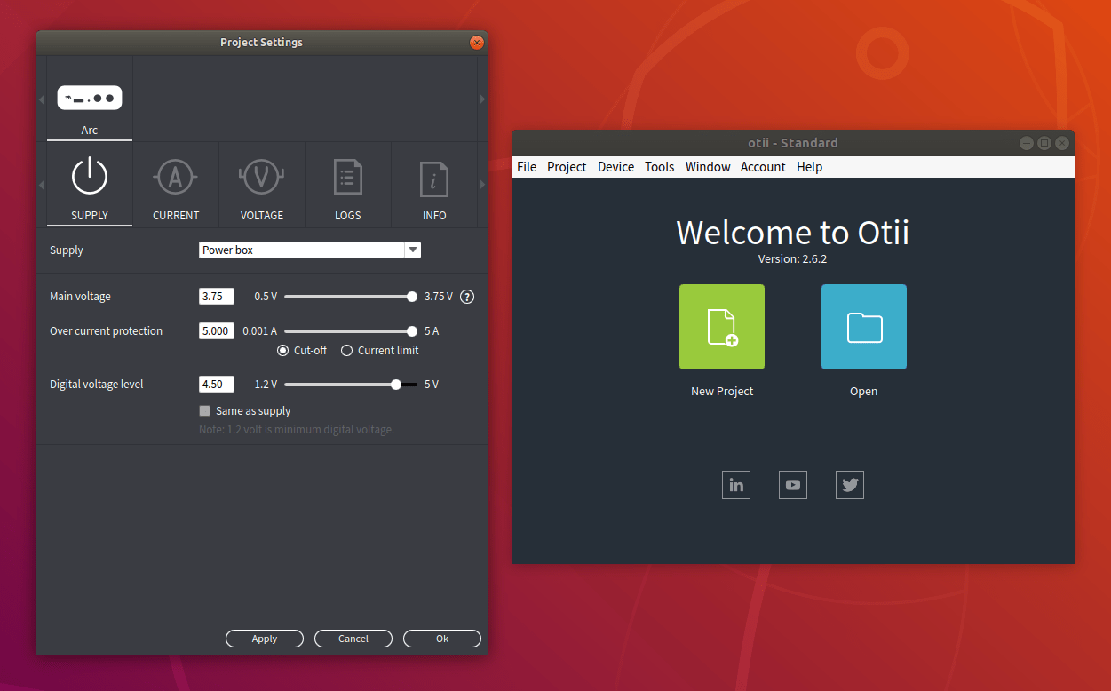
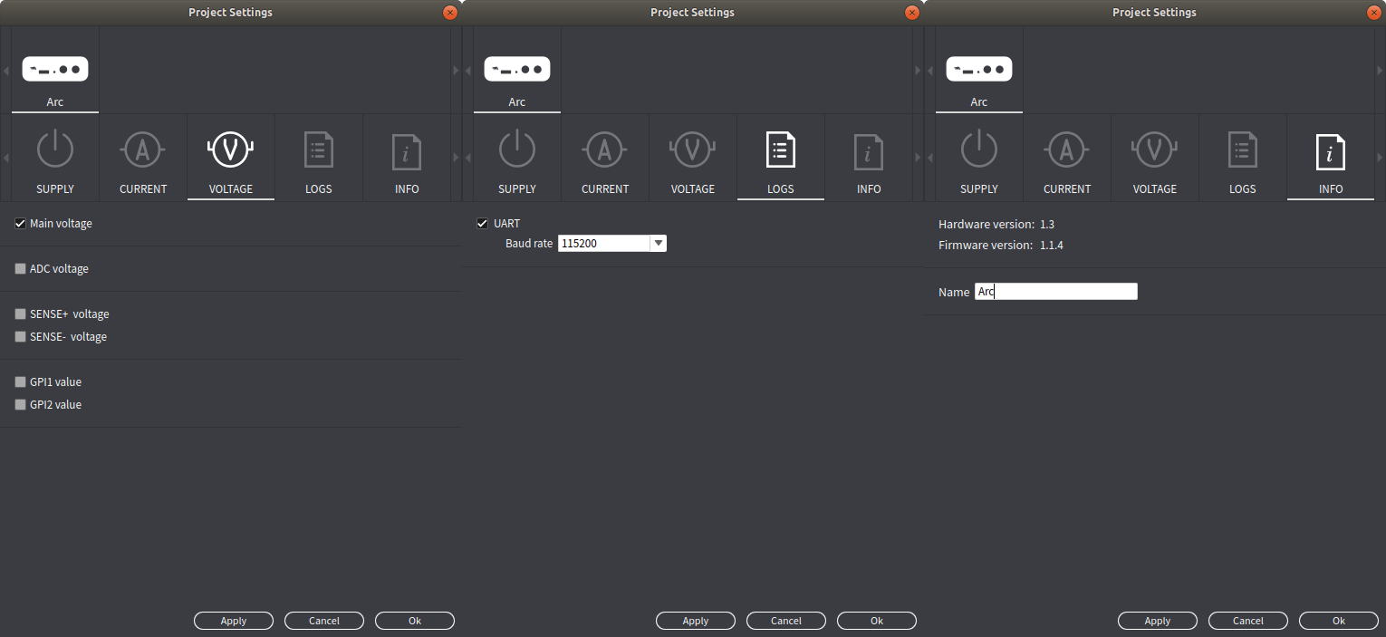
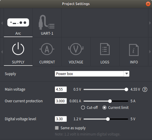
For the next step, I’ll mostly follow the quick start guide on Qoitech’s website. After clicking on New Project in Otii program, the Project Settings window shows up.
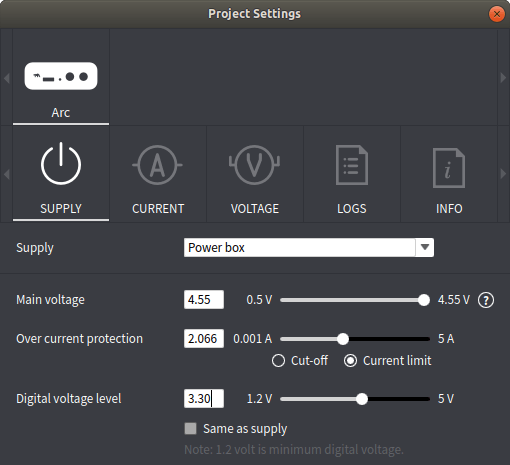
We can set the main voltage, over current protection and digital I/O voltage level. The first time, I could only get the main voltage up to 3.75V, but then I remembered I had to connect an extra 9V power supply to get up to 4.55V.
ANAVI Thermometer’s supply voltage should be 5V, but it still works at 4.55V, and I set the digital voltage level to 3.3V even though I’m not using the DAQ pins just yet.
Click OK to bring the main window, turn on power (green icon) and click on recordings to start seeing the current measurements.
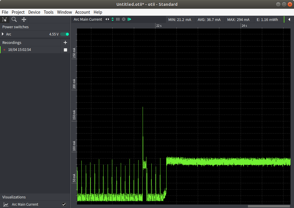
It will show a chart with the current drawn over time. You can select the data, zoom in/out, save to PDF etc…
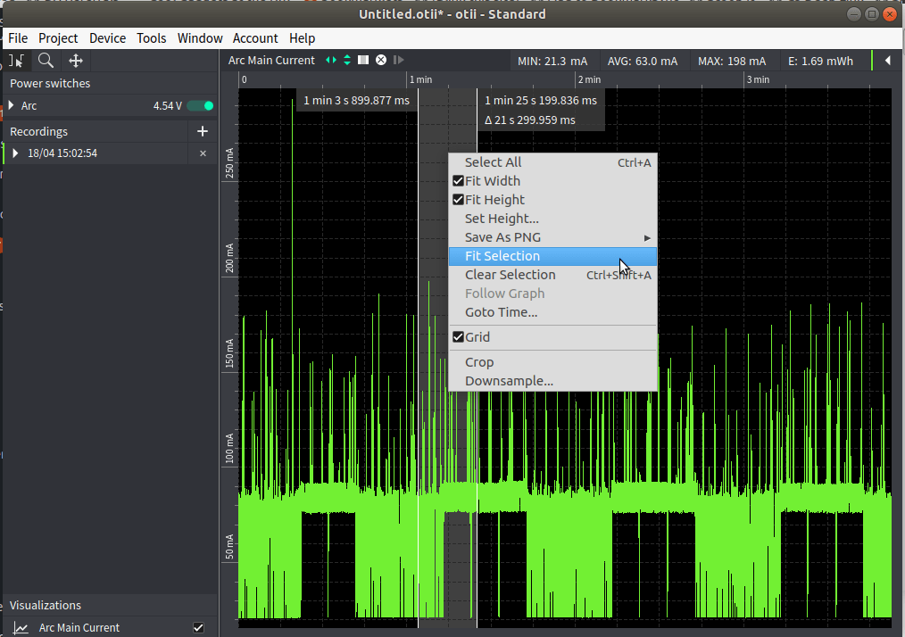
If you make some changes to your code or hardware, you can repeat the recordings and superpose them to compare the results.
The first time, I did not go through all the tabs in the Project Settings window, and here beside current, you can also enable various voltage recordings, and the UART console. For reference, I have hardware version 1.3 and firmware 1.1.4.
Hmmm. UART console? That looks interesting, so let’s hook up ANAVI Thermometer’s board UART pins to the Tx/Rx/GND pin on Otii Arc’s DAQ connector.
Now let’s see what it looks like with current and voltage chart and serial console.
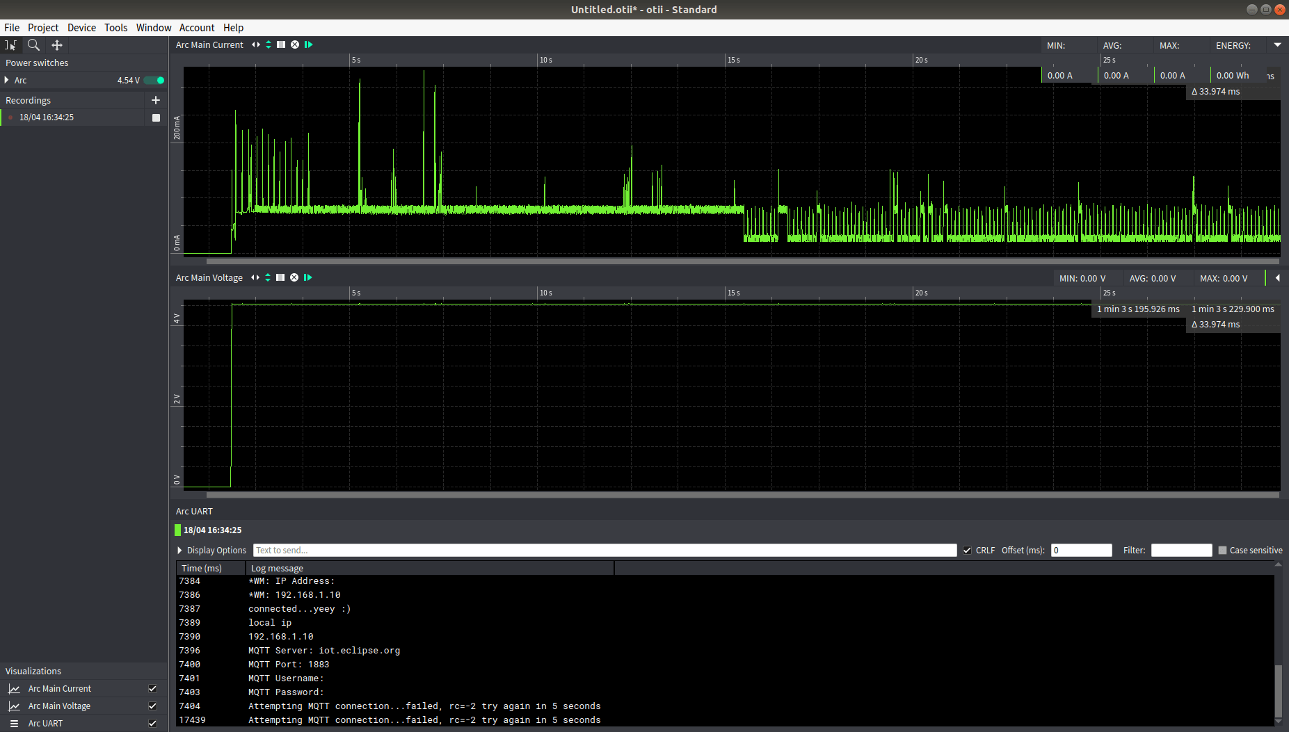
Nice, but wouldn’t it be better to just connect the UART to the computer directly and access it in a terminal instead? Nope:
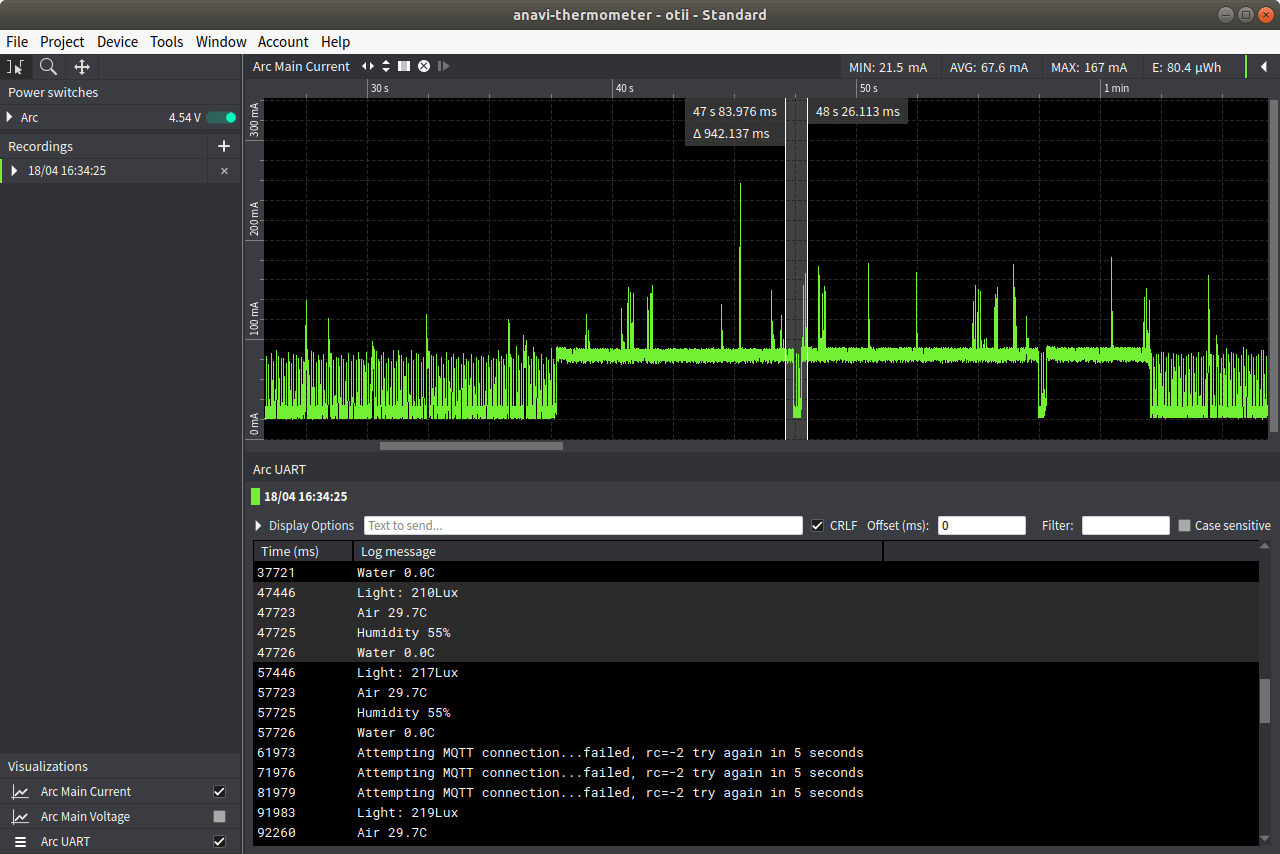
Because the console and chart can be synchronized, so if you can see a current spike, you can easily highlight it, and it will also highlight the corresponding lines in Arc UART serial console. Pretty neat.
Now if we look at the chart, the left side with a fairly low minimum current and lots of spikes us corresponds to the “Attempting MQTT connection message…” meaning the chip is trying to send data over WiFi, and the spikes down are when reading sensor data. That means the current draw is high when the board is theoretically “idle” but somehow the current and power consumption is much higher in that state. I’m guessing some calls to a sleep function during transmission, while there’s no sleep at all in the main loop.
Note ANAVI Thermometer is mostly designed to run from a USB power source, so power consumption is not really important, but as a fun exercise let’s try to make the board go into deep sleep for about 10 seconds
So let’s add the relevant code to the Arduino sketch:
|
1 2 3 4 5 6 |
// Press and hold the button to reset to factory defaults factoryReset(); // Enter ESP8266 deep sleep mode for 10 seconds ESP.deepSleep(10e6); } |
in the Arduino sketch to see how it looks like. ESP8266 deep sleep either requires user action (pressing the RESET button), or connecting RESET pin to GPIO16/WAKE pin of ESP8266 chip. So let’s do that with RESET being pin 1 and GPIO16 pin 4 on ESP8266MOD (aka ESP12-F) module.
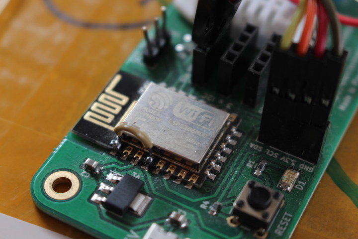
If you look carefully at the PCB, or easier, open the schematics, you’ll notice GPIO16 is also connected to D1 LED via R1 resistor. I first misread the schematics, and remove R1, but it’s not necessary, and instead, we need to comment out GPIO16 code in the sketch, basically all references to pinAlarm:
|
1 2 3 4 |
// const int pinAlarm = 16; ... //pinMode(pinAlarm, OUTPUT); ... |
Now we can build the program, and flash it to the board. I don’t think it’s possible to do so via Otii Arc, so I did so via a USB to TTL adapter instead. For people developing an actual product using a switch board is probably the right solution, and the Enterprise version of Otii program allows scripting so everything can be automatized, e.g. change program and save can trigger building the code, switching to the flash utility, then switching to Otii Arc and start measurements automatically. This is out of the scope of this review, and Jenkins integration is explained on Qoitech website.
As a side note, one of the steps in the instructions to flash the ANAVI board is to “Press and hold the RESET button on ANAVI Thermometer. Plug the 5V power supply in the jack of ANAVI Thermometer (without releasing the RESET button)”. It’s not always convenient nice you need to hold the board, the reset button and insert the micro USB cable. Otii software makes it easy as you can just press the button with one hand and click on the power on icon in the Otii program with the other.
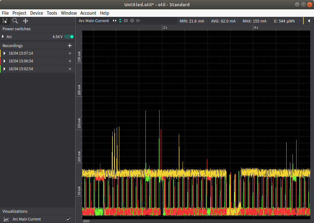
Now let’s run the program for about two minutes and so that we can compare the results.
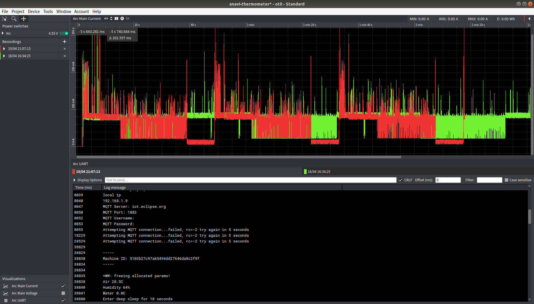
The old code is in green and the new code in red. With our new code, the board will start, read the sensor and go into deep mode for 10 seconds, and reboot.
It’s not easy to check the overall energy consumption by just looking at the chart, but we can select a period and can click on top right to corner to find out much less energy was used in the second run.
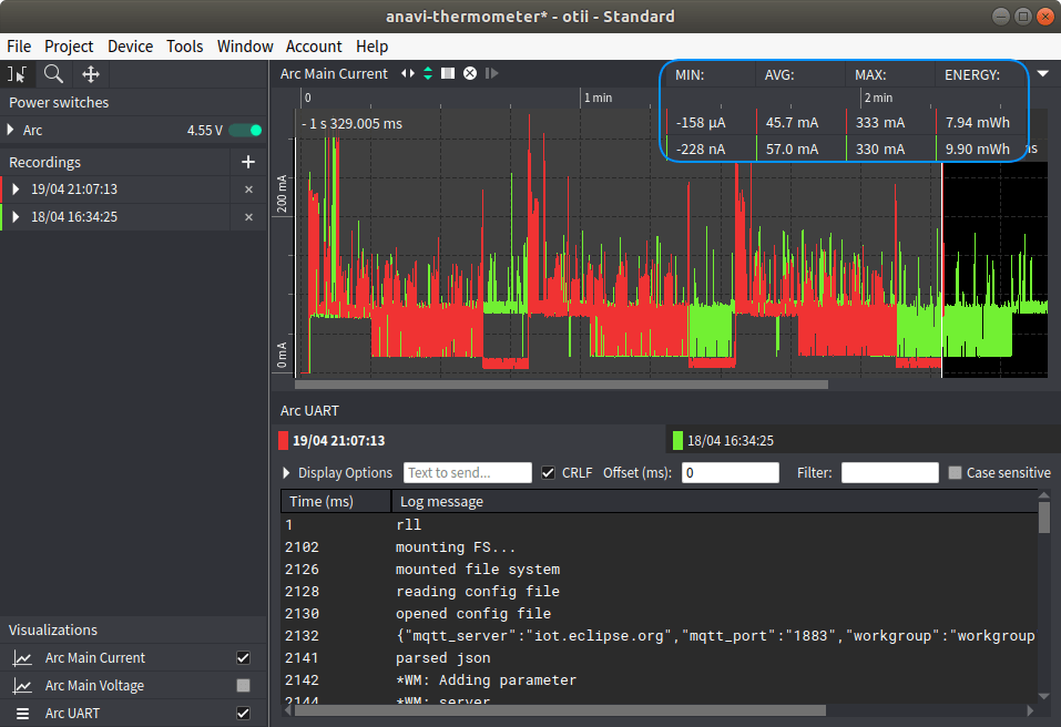
The first run used 9.90 mWh, while our “optimized” software consumed only 7.94 mWh. Somebody really wanting to use ANAVI board as a battery-powered WiFi thermometer, would likely skip the MQTT connection retried (go to deep sleep upon failure), and depending on the application go into deep sleep longer between measurements. The display may have to go as well, or be replaced by an E-ink display…
Using Otii Arc with A Linux SBC: Raspberry Pi 4
I’m impressed so far, but what if we use something a bit more power-hungry like a Linux SBC, namely Raspberry Pi 4 SBC?
I downloaded and flashed Raspbian Buster Lite to a MicroSD card, and created an empty ssh file in /boot to enable OpenSSH. We’ll see why it’s needed later.
The first time, I simulate a 4.55V/3A power supply, but the Raspberry Pi board is not too happy about this voltage:
|
1 |
21520 - [ 14.247822] Under-voltage detected! (0x00050005) |
So I vaguely remembered the device supports up to 5V, and the trick is to disable Auto range in the Current tab.

Just a quick note explaining what Auto range is for:
When this box is ticked a higher measurement accuracy interval is used if the current is between 0mA and 19mA. However, the Arc will not be able to keep constant voltage in this range for voltages above 3.75V in USB mode and 4.55V when the Arc is supplied from DC plug.
This won’t be an issue for us since Raspberry Pi 4 will never draw that little current. I’d also like to point out it’s possible to use boards with higher input voltage by inserting another power supply between Otti Arc and the DUT.
Let’s power on the board from Otii program, and…
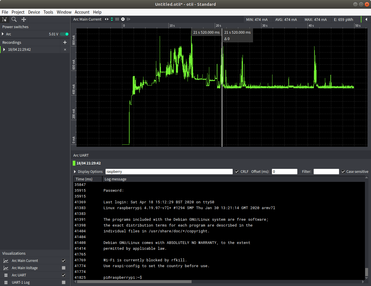
… success! Note that we are not shown the prompt for username and password, so I just inputted those because I know it’s been asked. That’s because the serial console only shows lines after CRLF is received.
The next step is to download sbc-bench.sh script before running the benchmark, but the serial console in Otii does not seem to like long commands so I connected over SSH to download it and install dependencies:
|
1 2 3 4 |
wget https://raw.githubusercontent.com/ThomasKaiser/sbc-bench/master/sbc-bench.sh chmod +x sbc-bench.sh sudo apt update sudo apt install git |
Let’s go back into Otii program to run the actual command:
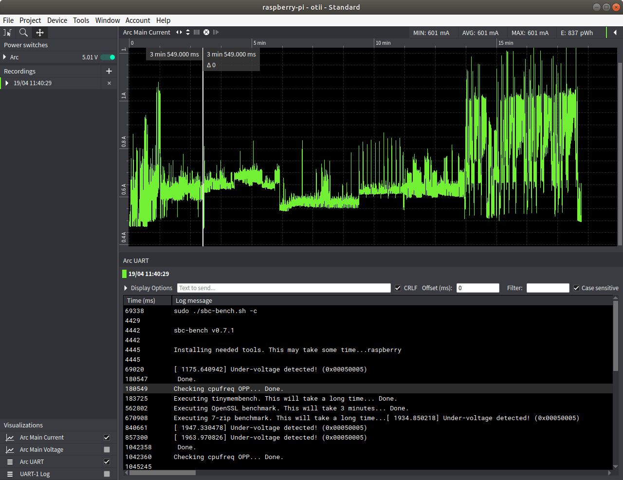
Note we type to blind type sudo password before carrying on. As the test run, we can click anywhere on the log to match the relevant section on the chart. Note that in a Linux terminal, the script with write “Executing tinybench. This will take a long time…” before running the test, and “Done.” after the test is executed, but in Arc UART terminal, the full line will only be shown once “Done.” is written (with CRLF), so ideally one would have to modify the script to show each step line by line unless there’s an option I missed in Otii program.
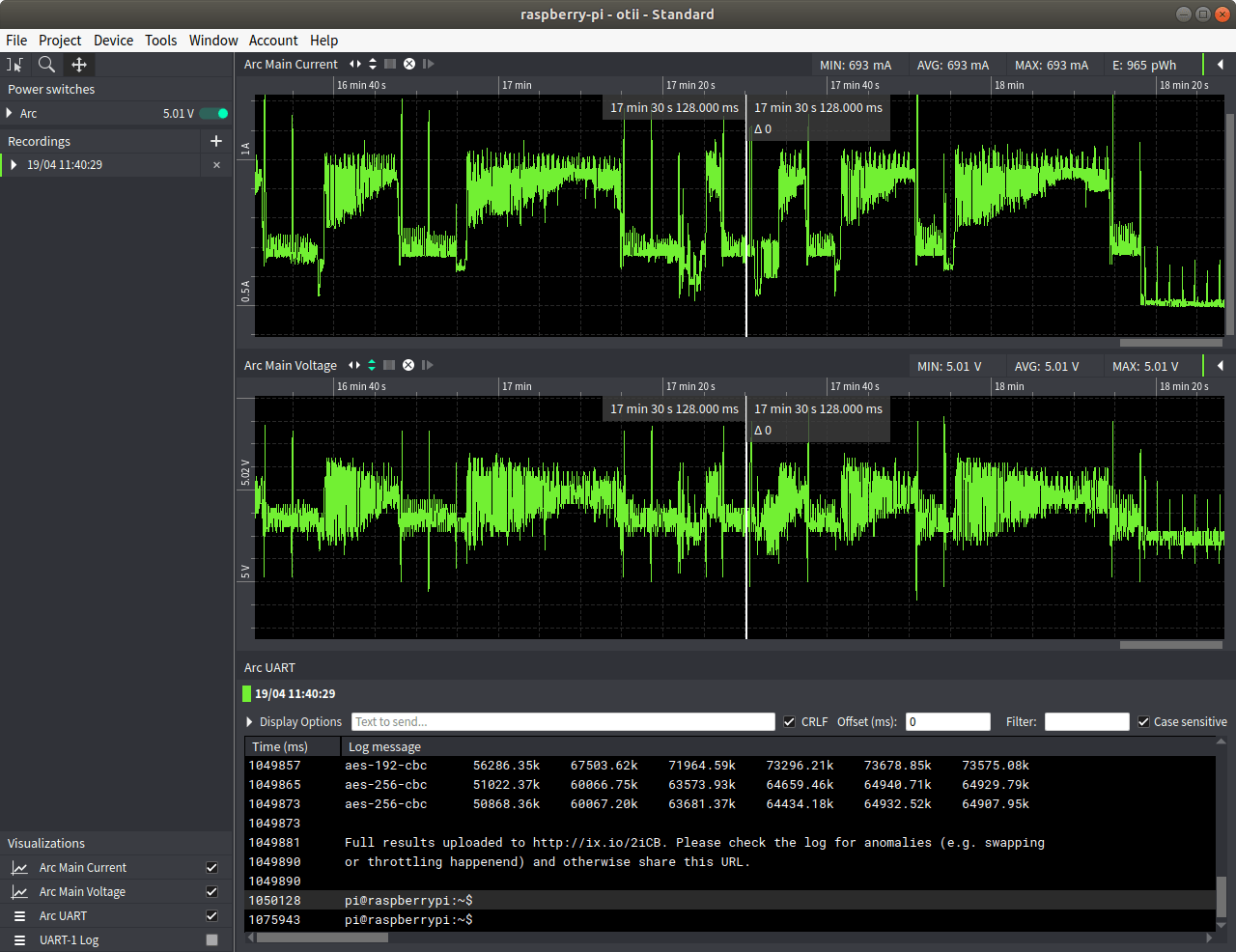
We can see some more messages about under-voltage detection when the script executes, but looking at the voltage chart, voltage almost never drop under 5V, and when it does it’s really small. Let’s assume the data from Otii Arc is correct. I have some previous experience as I did my own DIY power measurement board used with a PC connected multimeter to measure the power consumption of S812 and RK3288 TX boxes several years ago, and one of the problems was cable resistance. It turns out the banana plugs cable has a resistance of 0.33 Ohms which at the top current draw of 1.27A corresponds to a 0.42V drop at the other end of the cable, and this does not include the Micro USB cable resistance. That’s why I said that in some conditions, people may have to make their own cable with better quality wires and a shorter length in order to reduce the resistance.
If we look at the chart above, we can see that one the test is complete (pi@raspberrypi: ~$ in the serial console) it takes around one more minute before the current draw drop. Checking htop in the SSH console showed 7-zip still running, so maybe I just found a bug in the latest version of sbc-bench.sh script which may run 7-zip one more time.
To summarize, Otii Arc can be used with an Arm Linux SBC or slightly more power-hungry devices like mobile phones, but people must pay attention to a bit more details (like the resistance of power cables), and improvement to Otii terminal (i.e. serial console / Ark UART) implementation would be nice. But those are possibly not the main target applications of Qoitech’s customers.
I also noticed some bugs in Otii software with sometimes the cursor being shown at the wrong location (e.g. click on x, but the cursor is shown on x – 200 for example), or the dropdown list from top menu appearing in the second display of my laptop. Restarting the program solves those little nagging issues, and bug fixes are probably coming.
Qoitech Otii Enterprise Features
So far, I only used features from Qoitech Otii Standard version in this review, but there are also some extra features part of the Enterprise version that comes at extra costs such as Battery Profiling or Scripting. My device came with a free 2-week trial license activation key, and I suppose anybody who purchases the tool will also get the trial.
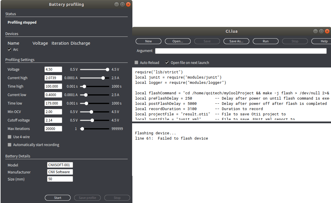
I have not been able to look into those features in detail due to time constraints, but basically this allows you to emulate a battery with various parameters, and write Lua scripts to automatize testing.
Try before you buy? Yes, you can!
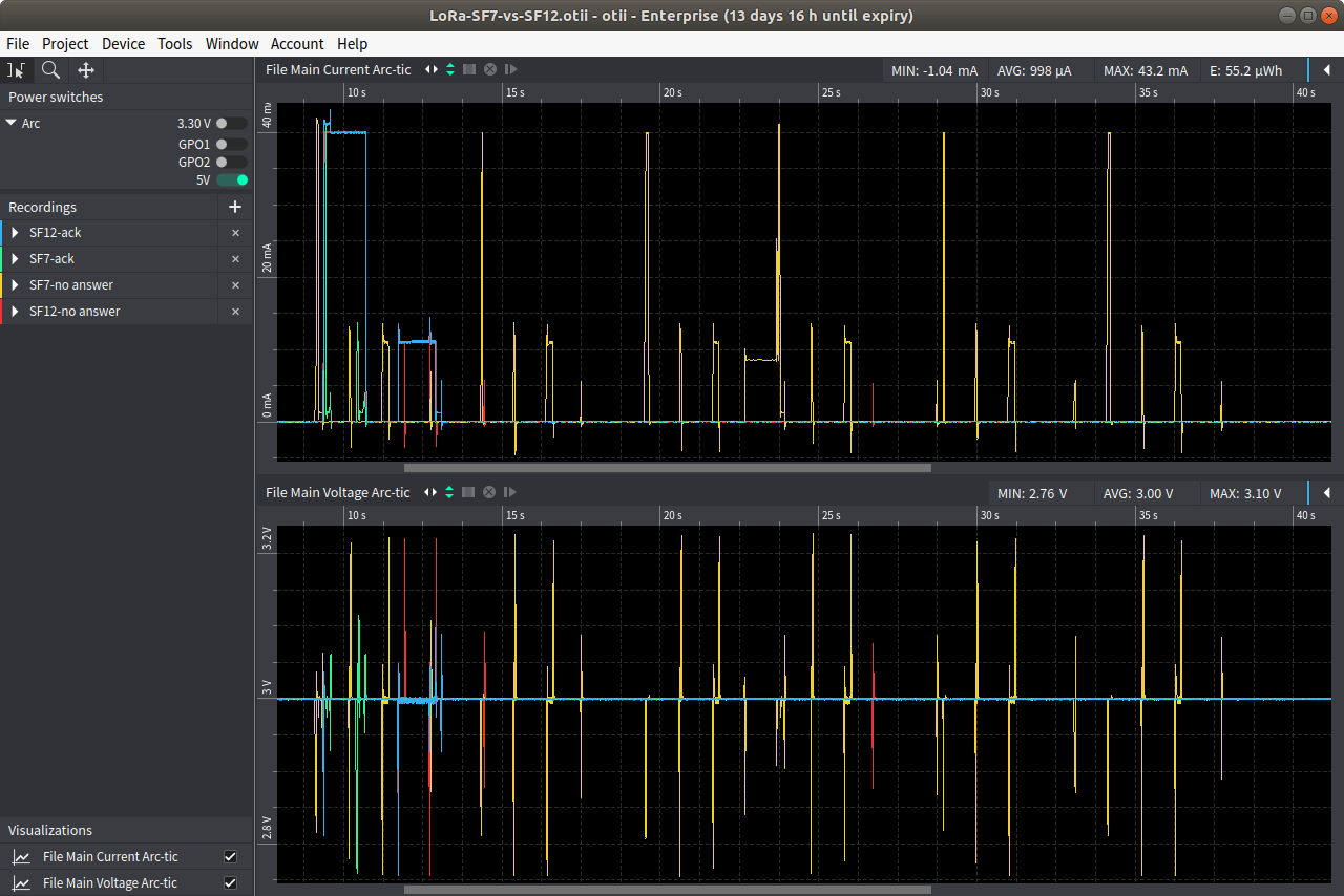
If you are interested in “Making Battery Life Great Again”, but have a limited budget, and prefer trying it yourself before spending over $500. That’s possible, as Otii program is free to download and the company pushed two example projects on Github which you can import before playing with the data and program’s features.
That also means there’s another advantage of Qoitech solution I did not think about initially: sharing data is really easy. If your company has offices around the world, or you need to work from home that’s a great feature.
Conclusion
I’ve done many reviews over the years, and from time to time, a product stands out and puts a smile on my face. Qoitech Otii is one of those, and if you need to develop battery-powered products it may save you and/or your engineers plenty of time, and pay for itself within a few hours. Qoitech Otii Arc (Standard) can be purchased on various distributors such as Seeed Studio for $575, while you’d need to contact the company to get a quote for the Enterprise version. You’ll find further details on the company website.

Jean-Luc started CNX Software in 2010 as a part-time endeavor, before quitting his job as a software engineering manager, and starting to write daily news, and reviews full time later in 2011.
Support CNX Software! Donate via cryptocurrencies, become a Patron on Patreon, or purchase goods on Amazon or Aliexpress. We also use affiliate links in articles to earn commissions if you make a purchase after clicking on those links.


Note that the license for the added features is a subscription.
I wonder how difficult it would be to emulate the most important features using e.g. a Blue Pill, an INA219 and a relay. That would get you high resolution voltage and current measurement, as well as console UART, and power control (on/off, at least). It would not allow you to vary the voltage, to test how your device behaves on the extremes, but the basic functions would be possible, at a cost of less than $20.
Hi there, the standard version of software is not able to be downloaded any more, do you know from where would it be possible to be downloaded? because i´ve been looking for it and it is nowhere.
Thank you in advance.
Will.
I understand they don’t have separate standard and Pro versions of the software anymore. They just release the software with all features by default.
What a pitty! Anyway i´ll try to find the stantard software thank you very much