
Karl Here. I am going to break up the review process for the Ortur Laser Master 2 Pro (LM2Pro) into smaller bite-size bits instead of one long review. I can get into more details and share what I learned. You can check out the initial unboxing and initial impressions in Ortur Laser Master 2 Pro laser engraver – First impressions. Let’s start first with focusing the laser.
Focusing the laser
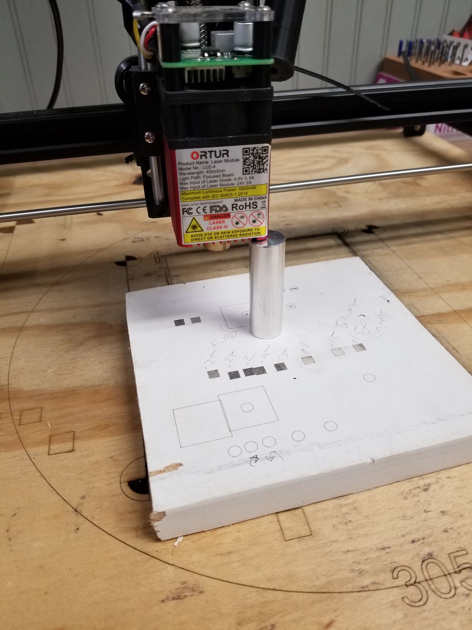
I have a problem, I don’t feel like I can reliably focus the same way every time so I created a little focusing contraption. I got inspiration from my CNC machine and Z probe.
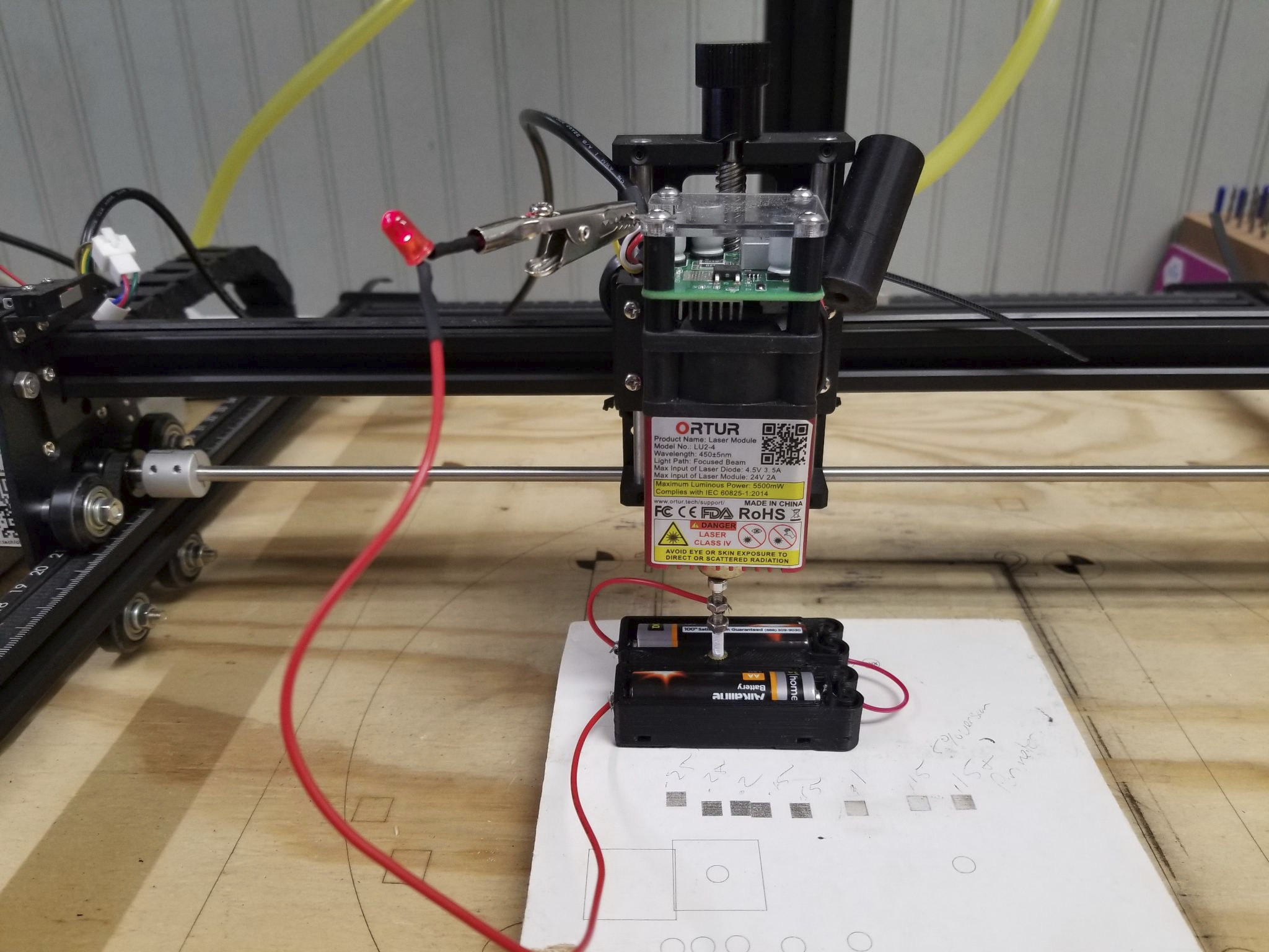
It is just a simple jig that completes a circuit when the lens touches the end of the M3 screw to illuminate the led. I feel like I can have better repeatability.
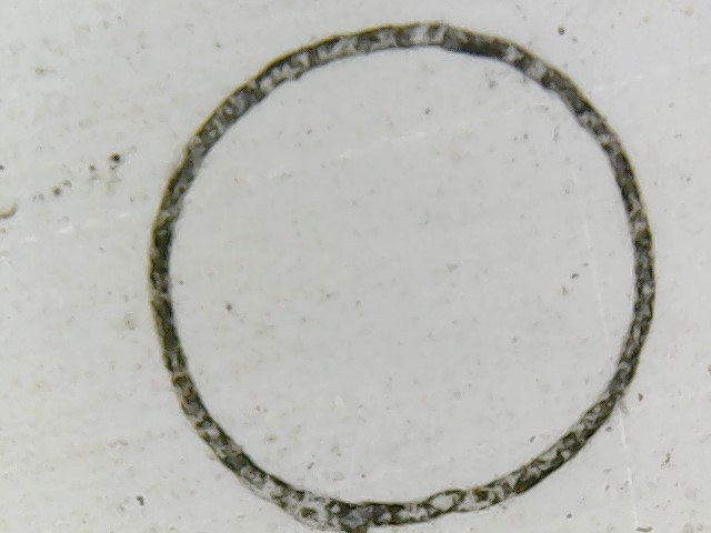
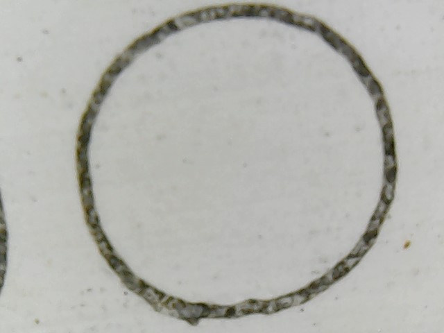
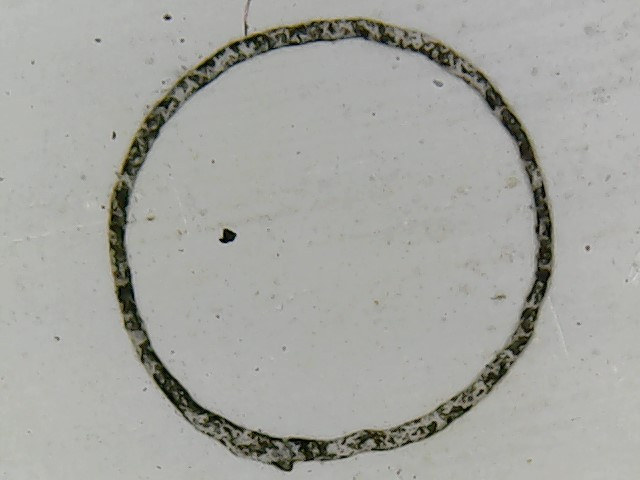
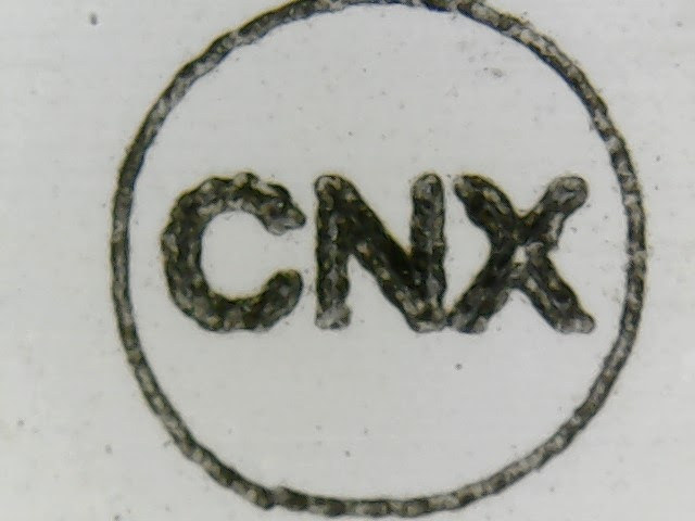
Before we continue, let’s talk about diode lasers. While I was trying to get my first low-power laser to work I did a lot of research on diode lasers. One key point to know is that the diode laser’s shape is not a circle, nor symmetrical. And more like a rectangle. From these pictures, it is pretty obvious that the laser orientation is vertical. Meaning the beam width is taller than it is wide. For the remainder of the tests, I set the lens focus to the clockwise position to have a uniform circle. I still have to do a lot more testing before I commit to this. Scratch that. I already changed my mind and went anticlockwise. After some debate, I want the smallest most focused spot. It should allow faster burns with a more concentrated beam.
Math
Let’s look at some things I have observed while testing. First fundamentals. Stepper motors move the laser around. The LM2PRO has 1.8deg motors with 16-microstep drivers, GT2 timing belts (2mm pitch), and 20 tooth pulleys. All the math equates to 80 steps per mm and that means .0125mm movement per step, AKA resolution. Here is a calculator for reference. (Maybe it would be interesting to test out .9 deg stepper motors?)
So if the machine moves 2 mm the controller sends 160 pulses. With that out of the way let’s continue.
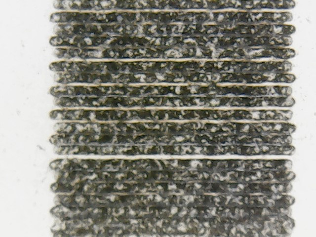
Notice anything wrong with this picture? That is because the Ortur had to approximate the steps. This took me too long to diagnose and put all the pieces together. I spent a ton of time testing and observing results. One of my biggest problems is having to throw away a lot of information I had read because it was misguided.
The first thing to understand when engraving pictures is that all movements must be full steps or you can end up with inconsistent gaps between scanned lines. Gaps are not a problem as long as they are consistent. When they are not consistent is when they become noticeable. Below is a chart with full step movements for the LM2Pro with 80 Steps per mm that I think are mostly realistic.
In the review guide, one of the items Ortur stated is that the laser/lens combo produces a smaller dot. In their words “Very small 0.08mm*0.15mm focal spot is a quarter of the area of other lasers which are 0.23mm*0.23mm”. Let’s use these numbers for our minimum and maximum values. I like between .1 and .2.
| Steps | Distance (in mm) |
|---|---|
| 6 | 0.075 |
| 7 | 0.0875 |
| 8 | 0.1 |
| 9 | 0.1125 |
| 10 | 0.125 |
| 11 | 1.1375 |
| 12 | 0.15 |
| 13 | 0.1625 |
| 14 | 0.175 |
| 15 | 0.1875 |
| 16 | 0.2 |
I have chosen Lightburn as my software of choice and am going to focus on engraving pictures right now. Lightburn is the most capable and as of the time of this writing I see 2 bugs.
Lightburn uses a term called line spacing. I see a ton of posts on Facebook about 300 dpi. This equates to a .085 dpi line spacing. In my opinion, this is just way too small a line spacing for just about any laser engraver, and for the LM2pro it doesn’t fall on full steps movements. It may mask the fact that the movements are inconsistent because they overlap so much but in turn causes 2 additional issues. Overly dark engravings and wasting time.
When the laser starts to engrave, it will burn one line then move the desired dpi or line spacing then go back the opposite direction and repeat until the entire image is burned. Let’s look at the G-code Lightburn produces. For this example, I set up a 5mm box directly in the center of the workpiece with no overscanning to keep things as simple as possible.
|
1 2 3 4 5 6 7 8 9 10 11 12 13 14 15 16 17 18 19 20 21 22 23 24 25 26 |
; LightBurn 0.9.24 ; GRBL device profile, absolute coords ; Bounds: X197.5 Y197.58 to X202.5 Y202.42 G00 G17 G40 G21 G54 G90 ;Changes to absolute coordinates M4 ;Laser power mode ; Scan @ 1000 mm/min, 100% power M9 ;Coolant command we can ignore G0X197.5Y197.58 ;First real movement Already not full steps but thankfully changes movement to relative movements. M3 ;Laser power mode ; Layer 1000.1 G91 ;Changes to relative coordinates G1X5F1000S1000 ;First laser movement to the right 5mm 1000mm/m full power G1Y0.08S0 ;Next move up .08mm with the laser off G1X-5S1000 ;Next move left 5mm 1000mm/m full power G1Y0.09S0 ;Next move up .09 with laser off…..wait what? G1X5S1000 G1Y0.08S0 G1X-5S1000 G1Y0.09S0 G1X5S1000 G1Y0.08S0 G1X-5S1000 G1Y0.09S0 G1X5S1000 |
I really like Lightburn, but I found that it has a couple of shortcomings. I shared my findings with the author and hopefully, he will fix this. The first issue is that it rounds all gcode movements to 2 decimal points. Illustrated above. Right off the bat when using any line spacing over 2 decimal places you are going to have alternating spacing like outlined above. Which if it was perfectly consistent would not be terrible. But it is not. If you ask LM2Pro to move .08mm, it can’t do it. .08 is somewhere between 6 and 7 steps. So it will be approximate. Let’s say that it moves 6 steps. 6 Steps is .075. From what I have read it will keep that .005 in memory. We now ask it to move .09 which is about 7 steps and you have a .0025 remainder. Which grbl keeps track of…. This will ultimately make a repeating pattern and depending on a ton of variables could be visible.
I propose 2 changes to Lightburn. First, give a choice for rounding in settings. With all movements being rounded to 2 digits we literally have only 3 realistic line spacing options. .1, .15 and .2.
Second, implement an option to make all movements full steps. I think this is important and I am willing to sacrifice the tiny bit of inaccuracy.
Laser testing with different line spacings
.125 line spacing seems like it should be the most ideal setting for the Ortur but due to software limitations, I cannot fully test it.
Let me show you why I feel this way. The test is on a prefinished piece of molding. The image is 30mm tall. 1000mm/s 50% power Constant power mode.
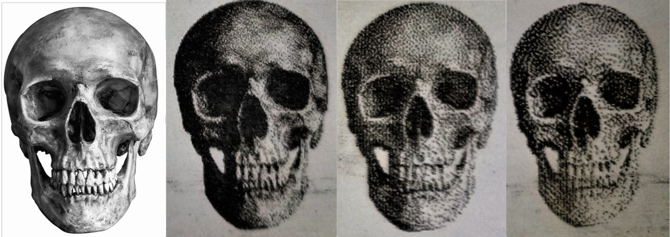
.1 looks really good but the dark areas are too dark because of all the overlaps. .15 and .2 look really good but not quite as high of a resolution. .1 took 4:42, .15 took 3:04, .2 took 2:28 and. Increasing the resolution seems to linearly increase the time, so on a bigger piece, the time savings can increase substantially. There is no doubt in my mind that the .1 above looks more crisp and pretty amazing but details are lost in the dark areas. To me, they all look good and I appreciate the pixelated look as well. Once it is more than an arm’s length away the dots go away anyway.
One way I can think of to potentially get around the image being too dark would be to manipulate the image and lighten it but I don’t like the trial and error aspect and would rather just load the image and it works every time. It appears like gamma adjustment is the best way to lighten only the darkest areas in Lightburn.
Additionally, I am relying on dithering to define dark and light areas. More dots = darker. Less dots = lighter. It seemed much easier to get immediate results with this method and less calibrating. Hypothetically the power variable could help overcome this limitation as well. Another thing to test and try out.
Wrap up for today
I don’t have any complaints so far with the LM2Pro so far and the only gripe is with Lightburn. I really like the new challenge of learning new hardware and a new technique to make things. I am also really surprised no one has investigated these software issues before. If someone has, I couldn’t find anything about it.
Thanks for coming along on the journey with me. If you would like to pick up an LM2PRO, you can do so on Ortur store or Amazon

Karl is a technology enthusiast that contributes reviews of TV boxes, 3D printers, and other gadgets for makers.
Support CNX Software! Donate via cryptocurrencies, become a Patron on Patreon, or purchase goods on Amazon or Aliexpress


For best results does the DPI of the original image have to be within the DPI resolution of the Laser?
Also the ability of the Laser to produce a grey scale of shades at the desired resolution, will affect the image look, to the human eye ?
Hi Karl, it’s pretty interesting to see that coming from different software and hardware we reach similar conclusions on the hardware limitations 🙂 I received my “40W” (15W) NEJE module which contains a fast axis correction (something that I previously tried to do myself and always failed). The beam is almost square. Aiming it at the wall shows about 27x29cm. By the way their new “30W” module also contains the FAC and should now be the best solution for the price. It took me a while to figure the optimal focus, but given that the spot is very thin and… Read more »