
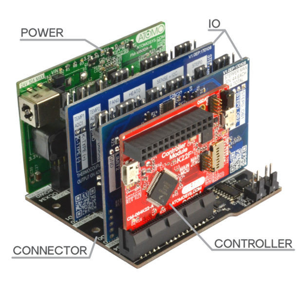
Atomo is a modular electronics protyping system comprised of four elements: Control, I/O, Power, and Connector, with the PCBs for each category color-coded with respectively red, blue, green, and black. The connector board connects power, I/O and control(ler) boards together in a way that’s supposed to be neater than most hand made prototypes.
 The whole ecosystem includes 15 different boards:
- Controllers with 26-pin Raspberry Pi compatible header
- 2 IO Module Controller (CM-M2K22-A) based on NXP Kinetis K22F MCU
- 4 IO Module Controller (CM-M4K64-A) based on NXP Kinetis K64F MCU
- 8 IO Module Controller (CM-M8K64-A) based on NXP Kinetis K64F MCU
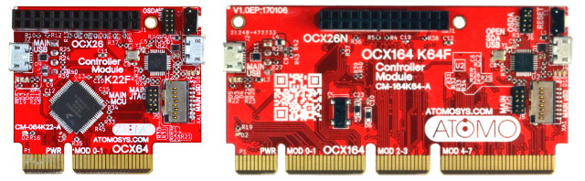
2 IO and 8 IO Controller Boards – Click to Enlarge
- Connectors
- 8 IO Module Connector (GM_M8P2_A) – Dim: 145mm x 100mm; power up to 40V @ 64A
- 4 IO Module Connector (GM_M4P1_A) – Dim: 71mm x 100mm; power up to 40V @ 32A
- 2 IO Module Connector (GM_M2P1_A) – Dim: 71mm x 65mm; power up to 40V @ 16A
- 2 IO Module Low-Power Connector (GM_M2P0_A) – Dim: 71mm x 65mm; Good for low power 5V/3.3V designs
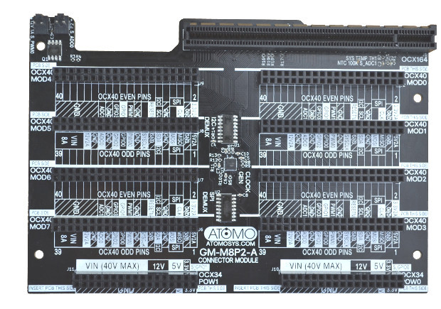
8 IO Modules Connector Board
- IO Boards
- Single Stepper Driver with Sensing IO Module (IO-001ST1-A)
- Triple Stepper Driver with Limits IO Module (IO-002ST3-A)
- Single Stepper and Heater Driver with Limits and Dual Temp (Thermistor + Thermocouple) IO Module (IO-003ST1TC1-A)
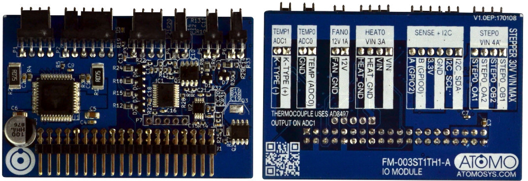
- Single Stepper and Heater Driver with Limits and Dual Temp (2x Thermistor) IO Module (IO-003ST1TH1-A) with ADC, I2C, SPI, PWM

Atomo IO-003ST1TH1-A – Click to Enlarge
- Power Boards
- 1X ATX Power Module (PM-ATX1X-A) for 1 ATX power supply with support for 3.3V, 5V, 12V plus a higher voltage up to 40V @ 32A
- 2X ATX Power Module (PM-ATX2X-A) for 2 ATX power supply with support for 3.3V, 5V, 12V plus a higher voltage up to 40V @ 64A
- 10A 5.5mm Barrel Plug Power Module (PM-VIN10A-A) – Input from 15V, 2A up to 24V 10A. Output: 12V, 5V, and 3.3V
- 13W POE Power Module (PM-POE13W-A) – Output 12V, 5V, and 3.3V; network data passthrough; auxiliary 5.5mm barrel plug 12V output.
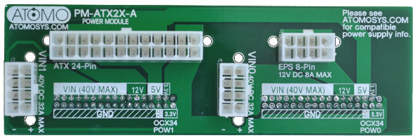
2x ATX Board

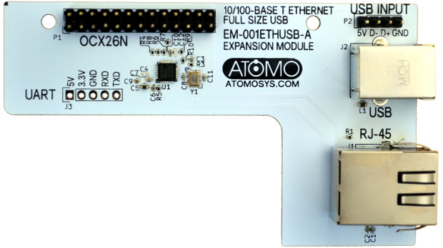
They also have one expansion module with USB input & UART headers, a USB port, an Ethernet port, and a 26-pin header, which you can use if you don’t connect the controller board to a Raspberry Pi.
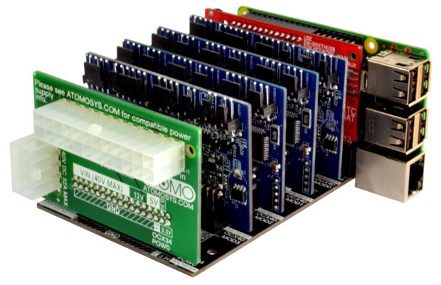
So now, you have to decide about your project’s power and IO requirements, select the boards, and put it all up together. That’s what it looks like when the Raspberry Pi comes into play together with four IO modules and one ATX power board.
Now you’ll need to program the NXP Kinetis based controller board using KDS and MCUXpresso, with low-level drivers using DMA provided by the developer, as well as board profiles with standard pin and clock configurations. ARM mbed compatibility, and RTOS integration are also planned for the future.
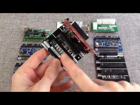
The video below introduces Atomo ecosystem, and shows a project with four LED strips.
Atomo has recently launched on Indiegogo, and the developer aims to raise at least $5,000 to fund mass production. Rewards start at $19 for the 2 IO controller board, and up to $48 for the 8 IO controller with the expansion board. The IO, power, and connector boards are not offered through Indiegogo – no wonder the campaign has not raised that much so far -, but a 10% coupon is included with all perks to purchase them on Atomo Systems online shop.
While Atomo Systems is a one person company, but the project has “Arrow Certification” meaning this campaign has a working prototype that has been certified by Arrow Electronics, so hopefully project failure due to technical or manufacturing troubles is less likely. Shipping is free worldwide, and delivery is scheduled for June 2017.

Jean-Luc started CNX Software in 2010 as a part-time endeavor, before quitting his job as a software engineering manager, and starting to write daily news, and reviews full time later in 2011.
Support CNX Software! Donate via cryptocurrencies, become a Patron on Patreon, or purchase goods on Amazon or Aliexpress. We also use affiliate links in articles to earn commissions if you make a purchase after clicking on those links.


Feels like revisiting the old motherboard idea. Albeit now the main processing board is also a card.
@agumonkey
Reminded me of the old ISA riser card for Dell etc too.
Thanks for the cohesive write-up.
@agumonkey Yep, it is at least somewhat inspired by desktop PCs. @Theguyuk Yes! A friend of mine had one of those machines.
The design process I took for the system was looking at what are the major divisions that make sense within a system. In this case, you can kind of look at the desktop motherboards and consider that the controller is actually removable. For me, the cheapest high pin count connector with a reasonable current limit was the PCIe ones. Just simply the best bang for the buck I could find. And, the density for the pins on these is not insane, so it will be possible for others to roll their own controllers without too much problem.
After that, I was mostly looking at how to make a very dense system that could be efficiently actively cooled. From a thermal standpoint, having the cards like this and being able to put airflow across both the front and back is a lot better than a large single board with high-power, high-temperature drivers. By limiting the amount of stuff that could go on one IO module via a usable but limited amount of connections and enough power on hand to drive a good bit of stuff without being excessive, it tends to spread out the heat within a system, making them potentially more efficient, reliable, and less likely to require active cooling for the same number of drivers in a more dense single board type setup.
The other side of this, for me, I’ve been developing electronic stuff (or worked with teams developing electronic stuff) for a long time now. One of the most common things I come up against is how much time you spend running basic stuff like power wires all over a prototype, which leads to harder to debug systems, and just time spent on things that don’t actually have anything to do with the novel part of the design. The system is really designed to make it much easier to do new system development faster, so you can get to a final integrated design for production faster, knowing that you just put all the discrete module schematics together and then clear out what isn’t used. You would even be able to follow the pattern for the PCB layouts from the module designs as a reference to make it faster to get to that PCB.
Anyhow, if you have any questions, please feel free to ask. Thanks!
Reminded me of my old Microtan 65 https://en.wikipedia.org/wiki/Tangerine_Microtan_65#Further_Expansion
Oddly enough, it looks like you could almost recreate one if you wanted to. We certainly have enough memory:
“Additional boards became available with time, including a 40K memory board – TANRAM, made up of 32K of dynamic and 8K of static RAM, bringing the total non-paged memory to 48K”
I was more a TRS-80 user during that time.
JuicyBoard is another modular electronics project but focusing on 3D printers/CNC/router or other robotics applications.
https://www.crowdsupply.com/plugg-ee-labs/juicyboard
@cnxsoft
Thanks for sharing, that is an interesting project. I would say the two biggest differences are the design decisions with power and controller. It looks like JuicyBoard would be great for building the systems they talk about, but there isn’t a simple upgrade path to make it ROS compatible (from what I can see) or to extend the controller functionality, so many good routes for general purpose robotics would not be on the table. The biggest drawback with the LPC controller they are using is that it will hit some limits as the Smoothieware project did, which is why they are moving on to a beefier controller and revising the firmware to be more efficient.
For power, they are only handling the 5V and 3.3V in the system, but it looks like they have a reasonable approach for how to add in higher voltages as needed. The PCIe connector is not the best choice for running power applications. I originally looked at using it for the IO modules, but each pin carries 0.5A rated current, so it would become a potential bottleneck very quickly for adding more power to an application. The JuicyBoard approach seems to bypass their module connector with separate wires for the higher power supplies. I wanted to keep the power all on the IO module connector for most applications, so to make building and prototyping a system more simple.