
[Update July 2020: It is now recommended to use Calibration Generator program instead of the Google Doc Spreadsheet in this article]
Hey, Karl here with a short article on retraction tuning. I really enjoy reviewing 3D printers and all things 3D printing with one exception…. when I have to calibrate retraction (aka retraction tuning). It takes so much time.
What is Retraction?
While 3D printing on a standard FDM printer, the filament is pushed with an extruder motor that has a gear attached. It pushes the filament, either directly into the hotend assembly or through a Bowden tube to the hotend. Molten plastic is then layered to produce a model. When it is printing nearly all prints require non-extruding movements. During the extruding moves pressure builds up and in order to stop stringing and blobbing during non-printing moves, a retraction happens.
There are 2 main variables that affect this: the speed it moves and the distance. In the past, I would take a calibration model and adjust these 2 variables and test. This can take a long time. First, I had to slice the model into G-code the printer can read and take a stab in the dark with variables. Then print. I had to wait for build plate to heat up…, then hotend to heat…, then the print time. It takes about 10-15 minutes for 1 test. Time adds up quickly.
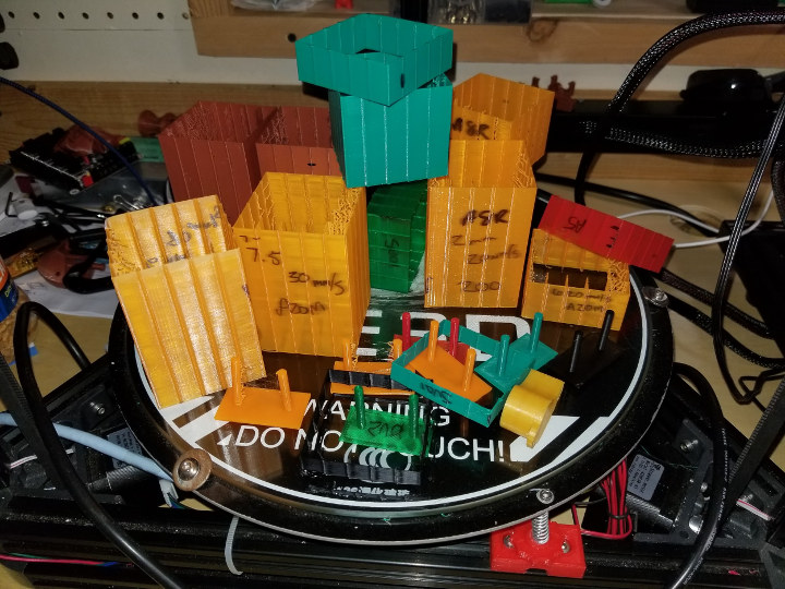
I am currently reviewing a printer – the Sovol SV01 – and I finally took the time and created a spreadsheet that generates G-code to programmatically test a lot of different combinations in 1 print. I think this is very useful and that is why I am sharing this here now.
Retraction Calibration Method & Spreadsheet
I setup the code in a Google Sheets doc here. This is a work in progress. I have only tested on the printers that I have on hand. If you have any suggestions feel free to email me. My email is in the sheets doc.
To start you will need to download and open in excel or open in your sheets instance. The link is for read-only.
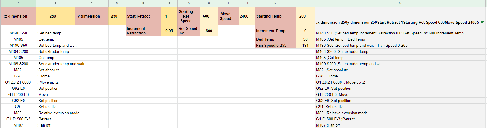
Let’s start with the G-code sheet. This is where you setup the G-code for your specific printer.
- X and Y dimension – Pretty self-explanatory. With the exception of a delta…set both to 0. Or any printer that homes to the center
- Start Retract – Shortest retraction distance it tests
- Increment Retraction – How much it increments for each test. There are a total of 16 tests
- Starting Ret Speed – First speed it test. From 0 to 5mm height (it will make more sense later)
- Ret Speed Inc – Every 5 mm in height it will increase the speed this amount
- Move Speed – The speed for non-extruding moves
- Starting Temp – Hotend starting temperature
- Increment Temp – Temp will increase this amount every 5mm in height I haven’t used this for testing.
- Bed Temp – Temp of the heated bed.
- Fan Speed – Fan speed at layer 2. 0 is off: 255 is 100%, 127 is 50%, 191 is 75%
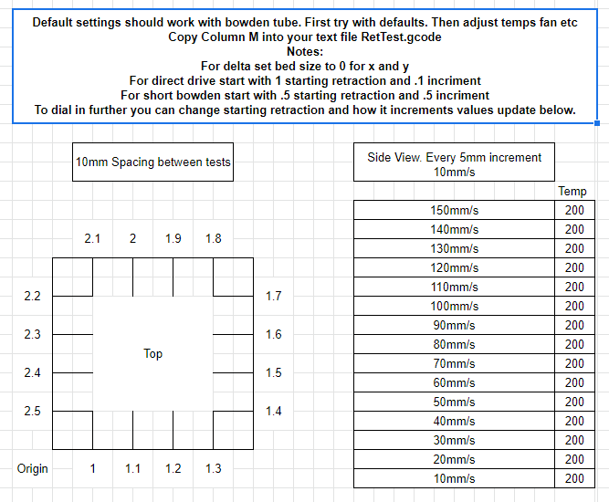
Once you set all your parameters copy column M into a G-code file all 30000+ lines. Before you print go into your settings and find out what the max extruder speed is. In Marlin 1.1.6 Control>Motion>Velocity>Vmax E and note the fastest movement. You can stop the print early once it reaches max speed. Before removing from the bed mark your origin corner. It should be obvious, but just in case it isn’t.
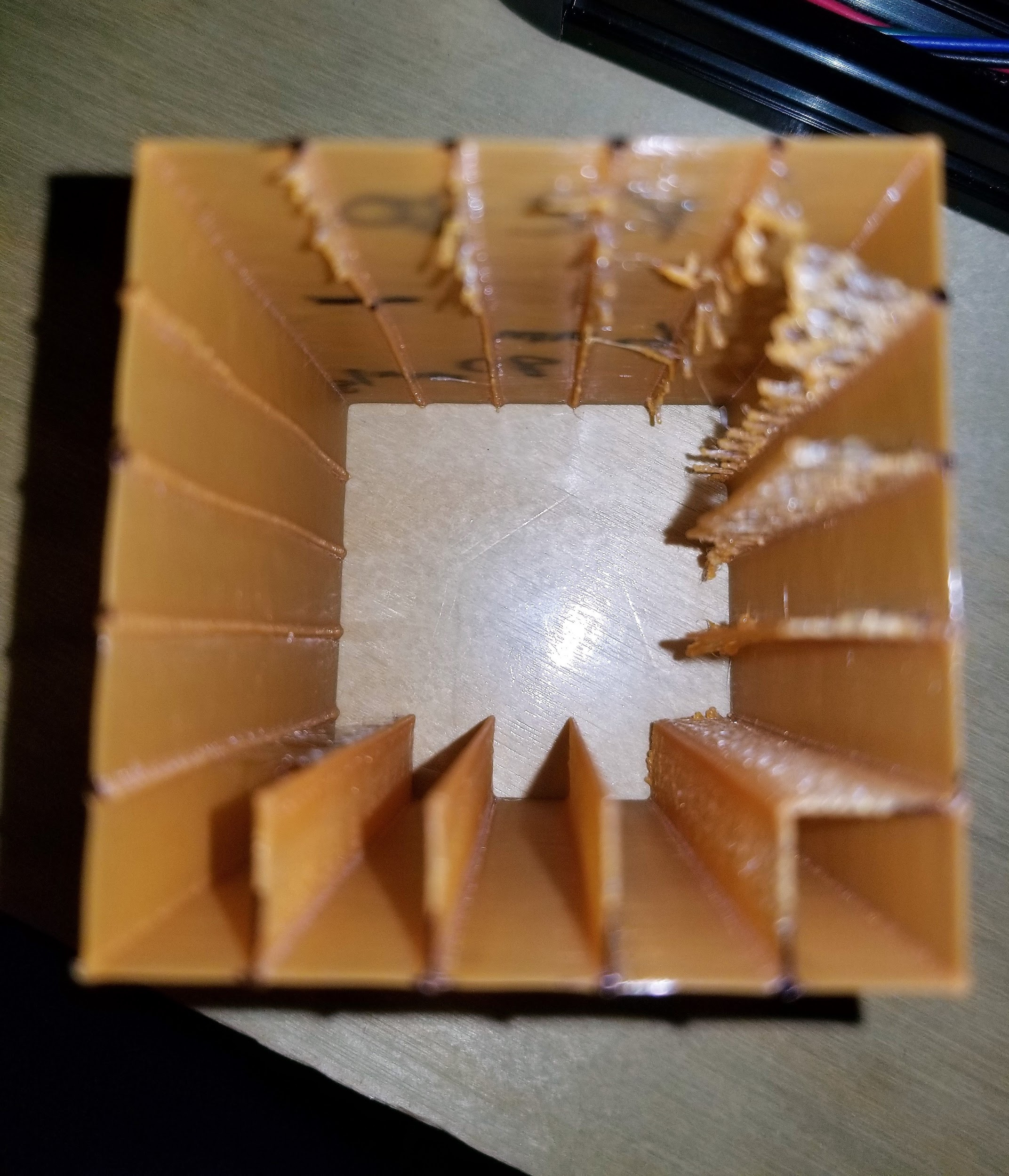
Here it is from the top. You can see as it moves around stringing blobbing gets better as the retraction increases. Origin is bottom left.
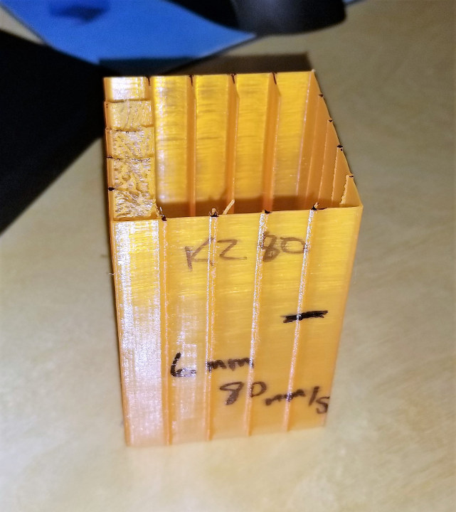
How it Prints
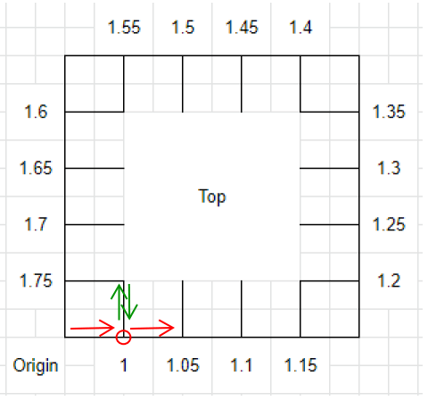
The print starts at the origin moves right …retracts at the circle then a non-extrude movement for the green arrows then un-retracts at the circle then starts over and moves all the way around.
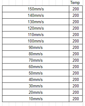
As the print progresses every 5mm in height the speed increments.
Interpreting the Print
Now that the print is complete we have to interpret the print. As you change the variables on the other sheet it will update the instructions sheet for easy interpretation. I mark the spot that looks the best. I then reference this page and measure to find settings. On some printers, I had to look very close and be very critical. You might even skip over the best one if the increments are too much. If you think that is the case print a second one with lower increments and increase your starting point based on the first print.
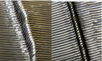
I have found that in general if it is hard to tell opt for the shortest fastest. It will lower your print time.
If you test this please leave some feedback on your experience. I can also start logging retraction settings on a separate sheet if you think it is a good idea. You can send me an email with your settings. If you want to see this in action I did a Livestream on YouTube where I tuned ABS live for the SV01.


Karl is a technology enthusiast that contributes reviews of TV boxes, 3D printers, and other gadgets for makers.
Support CNX Software! Donate via cryptocurrencies, become a Patron on Patreon, or purchase goods on Amazon or Aliexpress. We also use affiliate links in articles to earn commissions if you make a purchase after clicking on those links.


thanks for this!
There is a mistake at B24584. “Layer 176” should be “Layer 277”. The mistake runs to the end.
Thanks for the find. I will check it out and correct tomorrow
Fixed.
Hi Karl,
It seems to me that there is a mistake in gcode – E value is not change and is constant on every string. So filament has not extruded during printing.
Regards.
Sorry, i’ve found a reason – relative extrusion mode.
Regards.
Hi thanks for sharing. I tried using this file to test a Tenlog D3 Pro, but it doesn’t print anything.
The filament is continuously pushed up and down by the retraction commands but is not extruded by the printing commands.
I put a pen mark on the filament and after 10 minutes of printing it is right where it was at the beginning. It keeps going up and down but it never enter the Hot-End.
I even noticed that in my printer the Z axis is never increased: after 10 minutes of printing the head of my printer is always at the same height.
I have also seen that in the header of the gcode file, a command is given to move Z to 0.2, before the G91 command to set relative; then in the first line of the first level a G91Z 0.2 command is given again to move up again. This makes the first layer to be printed at 0.4 mm from the bed. It’s right? I think it’s a bit too high and pla won’t stick … Thanks for your attention. I am a newbie and could have written a lot of crap. Please be patient…
Is the print head moving correctly. All the movements are relative movements. I saw a few people try to modify the start gcode other then the variables I have outlined. If you would like I can do a Livestream on YouTube and we can figure out the issue. I am east coast time and can do after 9pm et.
I’m a newbie in 3d printing with no idea of gcode. I had that kind of issue, in my case was the regional configuration of windows. In some configurations (me from Spain), when you download the excel file, the OS changes “0.2” with “0,2”. Just change excel options.
I thing this is a very clever aproach, and motivates me to learn more about gcode. Thank you!
I’ve got same problem during first print.
Check regional settings in your OS. Look like you have decimal separator “,” instead of “.”
Is this for 0.4mm nozzle?
Yes sir
Got it, thank you.
If we wanted to change the nozzle size, what would be the correct way to update?
I used cura setting for a 10mm cube single wall and looked at the gcode….then doubled it.
Then do a find and replace.
What formula did you use for the flow?
I used cura setting for a 10mm cube single wall and looked at the gcode….then doubled it.
Me again. The file helps me a lot, but in my tests I notice a big difference with Cura Z hop “on” or “off”. I wonder if there is the possibility to include something like 0.2 Z hop in the file. Thanks.
I am currently doing some online python training with hopes to be able to make a Cura plugin. I think this would be a great option to include in the test.
So the file you currently have posted, does not print like the one in the photo’s on the site. It does not print the box and lines on the inside. So could you update the pictures or check the file for this? Because after printing it it all looked the same and no way to tell stringing.
hello.many thanks for you job!
pls make do model with brim ?
thx
I had problems with adhesion also, so I made an 80mm x 80mm x .5mm rectangle to print first, and then adjusted the start layer of the test to .7mm and printed it over top.
Hi, thanks for you work.
I’m tryng for my delta (wit a looooong bowden) and seem to work.
My test are “reversed” , the extrusion are on external direction, not to internal direction… is normal ?
If i understand i must find the wall/point/high with most reduced blob as possible ?
thanks
Marco
I got a brilliant suggestion and help to reverse and make the moves on the outside. Makes it easier to see.you are correct
i find a bug (think), fan is not powered off at the endo…. (and a bit of brim maybe useful)
Hi Karl … FINALLY! A proper tool to get the proper retraction settings instead of printing numerous tests with stab in the dark settings.
I am using a modified Anet A6 with a bowden E3D V6 clone hotend. I did find however, that the print is printing way over to the Xmax, Ymax, and had to reduce the bed size, and then it printed and stayed on the bed. My printer has X0, Y0 in the bottom left hand corner, but nowhere in the gcode do I see a move to a sort of middle of the bed?
This is nit-picking though. Retraction is really tricky, since it involved 3 variables: distance, speed and temperature. It’s really great to have a tool where you can tune all 3.
Hi Karl…I did some work on the spreadsheet – I tried the stock gcode on both my Anet and Ender-5 printers and it did the same thing – printed in the far upper corner, never went to the centre of the bed. Also, I noticed the fan setting wasn’t taken to the gcode either….. I’m happy to share my modified spreadsheet with you… Now both my printers work properly…..and I have my Anet dialled in…the Creality …hmmmm looks like we have a faulty Bowden tube coupler…!
Use the new version – the python program. I am on CR-10 S Pro and had the same issue.
Good day all. I am in the process of making this an app and not rely on this spreadsheet. I am expanding the capability. Hopefully have it finished within a week and tested. I will make an update when completed. Thanks everyone for your interest.
Tool is ready but need some testers.
Anyone up to test and provide feedback?
http://www.mediafire.com/file/lqwzk56ow361sb1/CalibrationTool1.2.exe/file
Email address is in google sheets doc for feedback.
Any feedback is appreciated.
After I get some testing done I will write up a detailed article.
Lots of improvements. Raft for better adhesion. More testing variables. Change nozzle size etc
Hi, cannot test print at moment but i confirm application is working, and generate a regolar gcode.
Hi Karl thanks for sharing, the app is fine.
My only suggestion is to add min/max/step value for both speed and retraction, this way we can control the height of the object.
Hi. After generating g code in the program, I got a bad result. The print was with a lack of extrusion. Loose model.
Hey if it is too underextruded. Change the extrusion multiplier. Try a 1.1 or 1.2
https://yadi.sk/i/m59yrrPwy5INGg
Picture my problem. But I’ll take your advice.
I see from your diagram that the nozzle is supposed to retract, move inside the cube, then move back out. Mine for some reason is doing the opposite – it’s retracting, moving out of the cube, then back in. Overall the lines on the cube seem to be identical after over an hour of printing
I’m using an Ender 3 pro w/ Bigtreetech mini 1.2 board installed and flashed to default 2.0.5.3 marlin release (no bltouch or led)
same here, i have the same setup and also experiencing this.
I changed to the outside for visibility.
Please test the link on the bottom of the instructions page. I created a windows program to do this.
Hi Karl. Thank you for this wonderfull tool. I use it on a Dagoma Neva/Magis (Delta) and it work perfectly.
I must just to replace start and end code and adjust the retract amount and speed values for good test.
May be you can update the software with a optional user start and end code.
But this tool is fabulous as this !
Thank you again.
Wassingue, France
hi, i tried your new EXE tool, it seems promising, i just report to you that there is a bug in the layer count if you change the layer height, no matter what you specify, it always produces a GCODE with 25 layers, suitable for 0.2 layer height in order to reach 5mm every speed increment, but you have to adjust the number of layers according to the specified layer height.. i was interested in testing it for a .08 layer height, and had to manually add all the missing layers. further, it prints only a couple of layer for the first speed, so there’s something else wrong there, thanks
Please contact me via Skype. I want to understand your settings please. I’m prahjister on Skype.
I did set this up for 25 layers per test regardless of layer height. I put transition markers in the corners to know where transitions are. I plan on doing an updated article very soon.
I finally understand the bug you found and is corrected in 1.3
Hi Karl,
I just wanted to give you feedback form my experience. I am sure that much of this will be resolved in your next article (which I cannot wait to read, btw). I just installed a dual gear extruder, so I wanted to re-calibrate my extrusion for it. I did a Google search, and this came up. After reading your article, I wanted to give your .EXE a try, but Chrome gave me several warnings that it might be malware (especially since it is an .EXE downloaded form MediaFire). Then, Windows Defender did not want to let me install it because it was created by an unverified user. Obviously, this is still in development, so I didn’t expect everything to be smooth, but as a first-time visitor to your site, it did deter me from using the .EXE file. Instead, I opted for the Google Sheet. Just thought you might want to know and maybe add a disclaimer or something for others in my position.
Second, I was not really sure what your description of the X and Y dimension parameters meant. You wrote “Pretty self-explanatory. With the exception of a delta…set both to 0. Or any printer that homes to the center.” I have an Ender 3 PRO (which does not home to center), so I figured I needed to set the x dimension parameter to 0 and the y dimension parameter to 0. Obviously, that did not work. After resetting them to 220, the gcode worked great. Just another heads-up for a description you might want to update in your next article.
Other than that, I think that everything worked out well. I am really impressed with the project and how well it worked out. It has helped me tune in on the right settings. I think that I will print one more lowered increments to help me gauge right where I need to be. This really is a great tool, so thanks for your hard work on it over the last year!
My last suggestion would be to ask if there is a way to condense this a bit—for example, printing a smaller square with only four or eight tests instead of 16. It would be a quicker way to hone in on the exact settings. Your .EXE might have that, so I’m sorry if that is already done. Again, thanks for everything!
Also, I just noticed the following in my OctoPrint window. I don’t think it matters, but you might want to know.
When printing the first few layers, they come out in 0.2 mm increments (0.2, 0.4, 0.6, etc.). However, after layer 45 (https://i.imgur.com/YjBWAUu.png), it starts to do increments of 0.19999999999 mm (https://i.imgur.com/7ifKNSN.png). It continues to decrease until layer 156 ish (https://i.imgur.com/Oi5hd4a.png), and then it starts to add 0.200000000001 mm per layer. At layer 188, it zeroes out again (https://i.imgur.com/HAco1Sj.png), but then it over-corrects until the end of the print (https://i.imgur.com/sG3wym1.png). Again, I don’t think this makes any difference in the final print (other than possibly impacting the “magic numbers”). I just noticed it while printing, and I am not sure why this might be caused other than because of a rounding issue in the Google Sheet.
I believe that is a rounding error in octoprint. It is hardcoded and no rounding is possible. If you can please use the EXE linked in the sheets doc. I won’t be maintaining the excel any more.
1.3 is available added ability to change the number of layers per test and the ability to limit the number of tests. I also found a bug because of this.
Really appreciate testing everyone is doing
http://www.mediafire.com/file/ffb43p1v5ewhmwk/CalibrationTool1.3.exe/file
Hi I tried to use 1.3 file above but at the start of the print it retracts so much before starting there is no filament to start the raft, it only starts laying down filament about halfway into the raft.
Thank you so much for testing. I think I know what happened. I added a zero out of the extruder to the start gcode. I suspect you printed something before this and it still had the old extruder in memory. I also added a 1mm prime to the start.
I really really appreciate the testing you guys are doing.
Here is the updated tool
http://www.mediafire.com/file/p7o919q9o85402e/CalibrationTool1.3.1.exe/file
hi Karl, is it possible to increase the size of the raft? this is to ensure that any oozing can be caught immediately on the early layers and make it obvious. right now the raft is only 5mm from the wall but the nozzle travels 10mm out from the wall.
Karl, very nice job with the automated program, much easier to use.
I think I found a bug, when you start the movement, there is a 6000 number i think is missing an F in front of it.
I also run into the too much retraction issue, i think right before the first layer a G92 E0 would suffice to clear that.
Great job! thanks for sharing!
Excellent work, thanks for sharing it.
I was curious why you doubled the flow from the 10mm cube? Wouldn’t that make you overshoot retraction?
I see that you use 0.44702 for each segment, assume that 1X would be 0.22351. When doing the same using S3D I got 0.38 using an extrusion multiplier for 1. Do you see any issues using the values from S3D ?
Thanks again
I would use the new program linked at the bottom of the instructions page. It is way more advanced. I use a formula now.
I found out today that some versions are showing up as a virus in windows. I opened up a case with Microsoft. After a little searching it looks like this is somewhat common using python.
Hello. How’s it going? How soon will the new version be available?
https://www.cnx-software.com/2020/07/08/3d-printer-retraction-calibration-vol-ii-calibration-generator-program-release/
All further updates will be to the webpage @
http://www.retractioncalibration.com/
You are the boss!!! Thanks for you effort. This program its amazing for me!!