
“Adding Open Hardware to Open Software for a More Equitable IoT” talk at FOSDEM 2021 discussed the importance of open-source hardware and software for IoT devices, notably to avoid getting a brick after the cloud service is suddenly terminated.
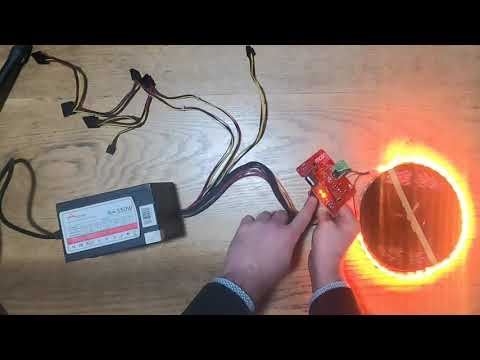
Adrian McEwen then specifically talked about his “My Baby’s Got LED” ESP8266 open-source hardware board powered by… a USB charger? nope. A battery? You’ve got to be kidding. Instead, the ESP8266 board is equipped with an ATX connector taking a standard power supply found in PC towers and desktops.
But why? That’s because the board is designed to control a string of Neopixels/WS2812 RGB LED’s, and a 500W ATX power supply can power up to 500 lights.
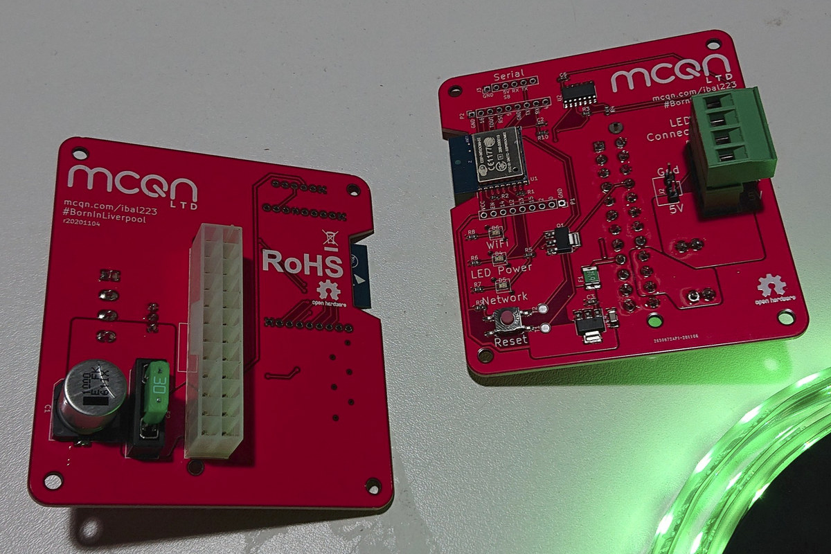
MCQN’s “My Baby’s Got LED” board specifications:
- Wireless module – ESP-WROOM-02 ESP8266 module with WiFi 4 connectivity
- LED strip connector – 4-pin terminal block
- Expansion – 2x 9-pin unpopulated 2.54mm pitch header for easy access to pins from the wireless module
- Debugging – Serial header for programming (and power while programming since you probably don’t want to connect the ATX power supply at that time)
- Misc – WiFi, LED Power, and Network LEDs; Reset button
- Power Supply – 24-pin ATX connector for power supply
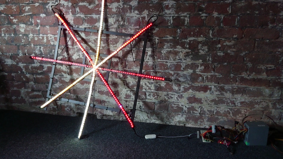
Designed with KiCad, the board is open-source hardware, and comes pre-programmed with the WLED webserver to control NeoPixel to make things easy. You just need to connect the LED strip and fasten the wires with the screw terminals, plug in the PC ATX power supply, and connect your phone or PC to the WLED WiFi access point to control the lights.
WLED also works with WLED mobile app for Android or iOS, and for integration with home automation systems, it also supports JSON and HTTP request APIs as well as MQTT protocol among others.
The board is sold on MCQN’s Tindie store for $55 plus shipping. You can also find additional information on the product page, and if you want to learn more about the development process, check out the slides from the FOSDEM talk.

Jean-Luc started CNX Software in 2010 as a part-time endeavor, before quitting his job as a software engineering manager, and starting to write daily news, and reviews full time later in 2011.
Support CNX Software! Donate via cryptocurrencies, become a Patron on Patreon, or purchase goods on Amazon or Aliexpress


I’m not to certain about using this board…..
You hook up a 500w power supply and then have a single JST or plug-in screw terminal going to the LED strip. JST can carry about 3Amps to 4Amps before causing too much voltage drop and the screw terminals can certainly carry more, but there is only a single one, so not much use in regards to doing power injection.
There also doesn’t seem to be a function to use 12v LEDs? Since most power supplies have a lot of 12v available to it, that would have been nice. 🙂
But worst, yes there is a fuse on there, but it’s useless with a 30Amp fuse in there. You want a fuse per injection line, especially when using a giant 500w power supply. If one of your injection lines gets a short now, it’s not going to be pulling 30Amps, it’s not going to pop the fuse since it can start a fire with a whole lot less Amps then that. The power supply also isn’t going to trip OCP, since it wasn’t designed for this use and it’s fine delivering 20Amps or whatever. So this thing can be quite dangerous, please don’t use it with a fuse more then 5Amps!
Regarding power usage of LEDs, 300LEDs use 65w at 100% RGB white, so 108w or 21Amp (hence why you need multiple power injection points) is needed for 500 LEDs, not 500w….
Maybe I just don’t see the idea of the board (500w power supply but you can use max 50w (10Amps) at 5v?) and like they say, it was developed with a singular idea in mind to drive their own prop, but then it’s really expensive.
Full Disclosure: I develop LED controller boards, but this post isn’t meant to say you need to use one of those, just to caution potential users of this one to use it with consideration!
When I first glanced at the article I was confused by the photo showing a single LED strip connector. I thought “maybe it’s an example and there’s room to solder plenty and address 10 LED strips in parallel”. I was too enthousiast indeed. I wouldn’t even pull 100W out of a single strip, as a few meters away the voltage drop must be significant!
I used a different approach to drive my non-addressable LEDs. I have four 2.4Ghz Milight FUT038 which I drive with this project: https://github.com/sidoh/esp8266_milight_hub
I own both the Milight wifi-hub and Miboxer bridge. Both are useless and in the drawer due to running Tuya. Tuya is very hard to integrate into another system, and you are stuck using a server in China.
The ESP8266 board with the nRF2401 chip is much cheaper (~$4) and it works way better due to local control over MQTT. No pointless need to route your on/off commands via China. My LEDs easily integrated with Home Assistant.
I have a couple of standalone Meanwell 24V supplies attached to the FUT038s. I picked 24V LEDs to lower the current passing through everything.
Not to disparage the designer too much, but an ATX supply is probably the worst option to use for powering 5V LEDs. Lots of current available on the 12V rails, but the 5V rails these days are pretty weak. Maybe if you were using the 12V distribution off to local 5V regulators closer to each strip it’d make sense.
Wouldn’t it be better to design this for a 5V meanwell supply or similar? They’re cheap and from most comments I’ve seen kinda well designed for what they are.