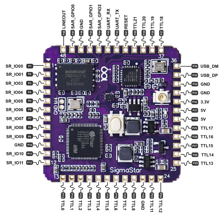
Based on its name, the DongshanPI-PicoW board/module aims to be an Arm Linux alternative to the Raspberry Pi Pico W with a SigmaStar SSD210 dual-core Cortex-A7 processor with 64MB RAM, an SSW101B USB WiFi 4 chip, plus a good amount of I/Os thanks to four 12-pin headers.
The module also comes with a 128MB SPI flash to run Linux, takes 5V power input, and offers a display interface up to 1280×800, USB 2.0, audio interfaces, and more in a small 31×31 mm form factor with 48 through and castellated holes that should be easy to integrate into compact devices.
DongshanPI-PicoW specifications:
- SoC – SigmaStar SSD210 dual-core Arm Cortex-A7 at up to 1.0GHz with FPU, NEON, MMU, DMA, 2D graphics accelerator, 64MB on-chip DDR2 RAM
- Storage – 128MB SPI NAND flash (Winbond W25N010)
- Connectivity – Sigmastart SSW101B 802.11b/g/n 2.4GHz 1T1R WiFi 4 module + u.FL antenna connector
- USB switch – Onsemi FSUSB30 2-port switch
- Four 12-pin 2.0mm pitch headers with castellated holes
- Display
- Up to 2x MIPI interfaces with 2 or 1 data lane and 2 clock lanes
- TTL output up to 1280×800 60fps
- Audio – MIC and DMIC inputs, Line out, 8-channel I2S/TDM with 2/4/8-channel Rx, 2-channel Tx
- Networking – 1x 10/100M Ethernet
- USB – 1x USB 2.0
- Misc – 1x SDIO 2.0, 2x SPI, 2x I2C, 4x UART, 4x PWM, GPIOs
- Display
- Security Engines (AES/DES/3DES/RSA/SHA-I/SHA-256)
- Misc – Reset button
- Power Supply – 5V via I/O pins
- Dimensions – 31 x 31 mm (estimated)
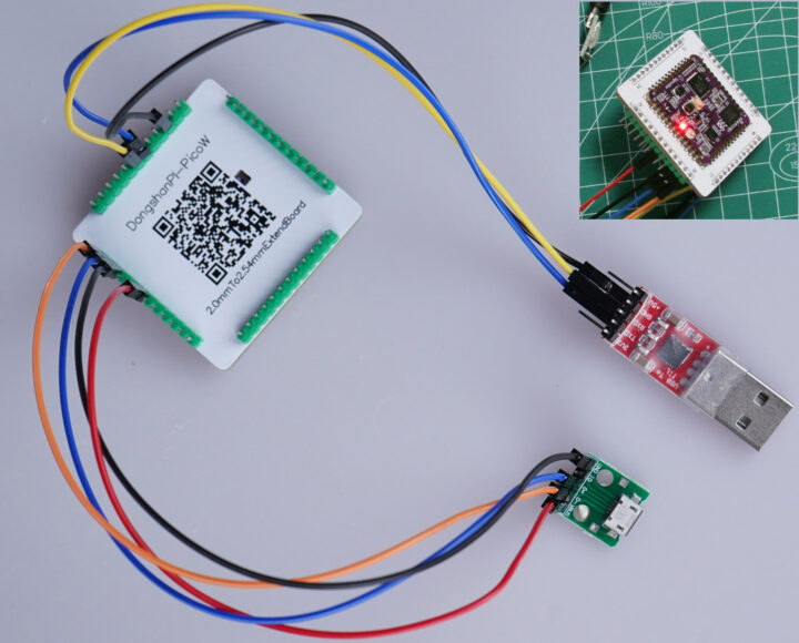
The lack of a physical USB port makes the PicoW module great for integration into projects, but you’ll need some wiring for power and programming. The photo above shows the DongShanPi-PicoW soldered to a 2.0mm to 2.54mm pitch adapter with a micro USB board connected for power and flashing the firmware, and a USB to TTL debug connected to UART to access the serial console.
You’ll find some documents in Chinese as well as the schematics and a Linux image and flashing tools in the Wiki. Questions can be asked on Twitter or in a forum. SigmaStar SSD2xx processors have some support in Linux mainline, and additional information can be found on the Linux Chenxing website. I suppose the module could also replace the Raspberry Pi Zero W for some lightweight applications that may not need 512MB of RAM or an HDMI display. Connecting a MIPI display is possible, but you’d need to find a display that works with the module.
The DongshanPI-PicoW is sold on Aliexpress for $6.71 plus shipping (around $10 in total), but without the 2.54mm pitch adapter board, so you’d need to do some light soldering to wire the board for power and the serial console.

Jean-Luc started CNX Software in 2010 as a part-time endeavor, before quitting his job as a software engineering manager, and starting to write daily news, and reviews full time later in 2011.
Support CNX Software! Donate via cryptocurrencies, become a Patron on Patreon, or purchase goods on Amazon or Aliexpress


Sort like Pine Ox64?
Not sure what Ox64 is useful for since many of the Linux drivers are not available, especially the WiFi, USB etc. The description in the article “have some support in Linux mainline”, does not look much convincing for dealing with those products.
That’s pretty interesting and aligned with the principles @dgp encourages, which is to use Linux instead of crappy wifi stacks to put into IoT. Here it’s really a board to embed in a device and not a tiny computer, contrary to the Breadbee which is definitely a tiny computer since it has most I/Os already available on connectors. I think however you made a tiny mistake on the SPI flash reference, it’s not a W25Q128 which would be a 128Mb, but a 25N010 which appears to really be a 128MB one (pretty cool these days!). Anyway all such linux mini-pcs… Read more »
Yes, you’re right about the flash. I just copied the part number from the Wiki without thinking too much about it.
I was ready to go click buy on a few of these but….. 2mm headers? Are you kidding me? There goes most of the simple use cases unless you solder it down to an adapter board–which is a complete waste of more PCB area. That’s just a huge facepalm.
I’ve got a board with the same chip but it fits on a standard breadboard if you have a soldering iron..
https://github.com/breadbee/perdita
Yeah that’s in part why I said that it’s not a developer board but just a board to embed into a final product. Also for development you don’t even want connectors on the 4 sides, that’s not much compatible with bread boards. Or at least you want the important ones on two opposite sides, and the other ones can be turned up for optional use.
2mm castellated holes are industry-standard. I agree it would have been way more user friendly if they went with a breadboard-friendly design with the holes on two opposing sides (and maybe some optionals on a 3rd side) but such is life, and if this board is worthwhile some other designs might pop up. But working with an ESP8266/ESP32 is not the end of the world either, even if you deadbug it. This is marginally bigger, it’s not a huge loss of PCB
If it were just castellated, you’d have a point (assuming what you say about 2mm being a standard is true), but this has holes in it as well and that means headers of some type. And, for those, 2mm is not a common standard, 2.54 is.
Please someone help me push the 700 commit backlog for these chips!! 😀
You’ve accumulated way too many, it’s difficult to squash them and figure the related commit messages. But I agree your work deserves help. Given the amount of experimentation you had to do, maybe it will be easier to start from the final state and try to cut them into individual features only. These chips have a great potential, and last time I used the breadboard on stage it was stable enough to make me confident I could engage in the conference’s opening keynote with it for a live demo 🙂
How does one program/debug the chip? I don’t see any jtag/swd nor setting up the toolchain.
For this one I don’t know. On the breadbee (which served to put the software in a usable form), I didn’t need JTAG since @dgp had already done a lot of the work to get it to boot. I only used the serial console, and an SOP8 clip to reflash a kernel image or boot loader when I messed up with the one there. Anyway once you get something that boots more or less reliably you generally don’t need the JTAG access anymore. And the toolchain is just any regular armv7 one, nothing extraordinary here.
There is jtag:
https://twitter.com/linux_chenxing/status/1616395185528922112
You can program the on-board flash in two ways:
A weird spi over i2c interface that is on the debug serial port (yes, i2c at the same time as a uart..)
Or via the USB support in the boot rom.
I wonder what kind of idle power consumption this baby has? A decent openwrt port would be pretty great for this device.
taobao link ?
I just got my boards and they are with adapter pcb visible on the second photo. So this is the best choice, you have small board size or solder it and you have easy 2.54 pin access.