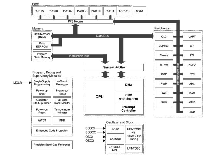
The newly introduced Microchip PIC18-Q24 8-bit MCU implements security measures such as the Programming and Debugging Interface Disable (PDID) feature and optional support for an immutable bootloader, as well as support for Multi-Voltage I/O (MVIO) to interface with digital inputs or outputs at different operating voltages without the needs for level shifters.
While it’s fun to find a new MCU platform that you can hack via serial, JTAG, or other debug interfaces, it can be a security issue, and the Microchip PIC18-Q24 aims to make that impossible by disabling programming and debugging interfaces and the 8-bit microcontroller also offers an option to make the bootloader impossible to modify once a specific configuration bit has been set.

Microchip PIC18-Q24 key features and specifications:
- MCU core – 8-bit C compiler optimized RISC core @ up to 64 MHz
- Memory – Up to 4 KB of Data SRAM Memory
- Storage – Up to 64 KB of Program Flash Memory, 512 Bytes Data EEPROM
- Multi-Voltage I/O (MVIO) for support for a second voltage domain (VDDIO2) set within a 1.62V to 5.5V range
- 4x Direct Memory Access (DMA) Controllers
- Vectored Interrupts
- 128-Level Deep Hardware Stack
- Digital Peripherals
- 3x 16-Bit Pulse-Width Modulators (PWM):
- Timers
- 3x 16-bit Timers (TMR0/1/3)
- 3x 8-bit Timers (TMR2/4/6) with Hardware Limit Timer (HLT)
- 2x Universal Timers (TU16A/TU16B)
- 2x 16-bit timers can be chained together to create a combined 32-bit timer
- Windowed Watchdog Timer (WWDT)
- Configurable Power-up Timer (PWRT)
- 8x Configurable Logic Cells (CLC)
- 1x Complimentary Waveform Generator (CWG)
- 2x Capture/Compare/PWM (CCP) Modules with 16-bit resolution for Capture/Compare modes, 10-bit resolution for PWM mode
- 1x Numerically Controlled Oscillator (NCO)
- Programmable CRC with Memory Scan
- 2x UART, 2x SPI, 2x I2C (SMBus, PMBus Compatible)
- 1x 8-Bit Signal Routing Port Module:
- Device I/O port Features
- 24x I/O pins including four MVIO pins powered by VDDIO2 (PIC18F24/25/26Q24)
- 35x I/O pins including 12 MVIO pins powered by VDDIO2 (PIC18F45/46Q24)
- 43x I/O pins including 12 MVIO pins powered by VDDIO2 (PIC18F55/56Q24)
- Peripheral Pin Select (PPS) – Enables pin mapping of digital I/O
- Analog Peripherals
- 10-bit Analog-to-Digital Converter with Computation (ADCC) for up to 30 external channels, up to 300 ksps
- 8-Bit Digital-to-Analog Converter (DAC):
- 2x High-Speed Comparators (CMP)
- 2x Zero-Cross Detect (ZCD) modules that can detect when AC signal on pin crosses ground
- Voltage Reference – Fixed Voltage Reference with 1.024V, 2.048V and 4.096V output levels
- Enhanced Code Protection
- Programming and Debugging Interface Disable (PDID) through the ICSPDIS Configuration bit
- Storage Area Flash (SAF) one-time programmability through the SAFLOCK Configuration bit
- Reset
- Low-Current Power-on Reset (POR)
- Brown-out Reset (BOR)
- Low-Power BOR (LPBOR) Option
- Programming/Debug Features
- In-Circuit Serial Programming (ICSP) via 2x pins
- In-Circuit Debug (ICD) with 3x Breakpoints via 2x pins
- Debug Integrated On-Chip
- Voltage Range
- VDD – 1.8V to 5.5V
- VDDIO2 (Multi-Voltage I/O) – 1.62V to 5.5V
- Power Saving modes
- Doze – CPU and Peripherals Running at Different Cycle Rates (CPU Is Typically Slower)
- Idle: CPU Halted While Peripherals Operate
- Sleep: Lowest Power Consumption
- Peripheral Module Disable (PMD) – Ability to selectively disable hardware modules to minimize active power consumption of unused peripherals
- Low Power Mode Features:
- Sleep: < 1 µA typical @ 3V
- Operating Current: 48 µA @ 32 kHz, 3V, typical
- Package – 28-pin SPDIP/SOIC/SSOP/VQFN, 40-pin PDIP/QFN, 44-pin TQFP, or 48-pin TQFP/VQFN
- Temperature Range – Industrial: -40°C to 85°C; extended: -40°C to 125°C
There are currently seven different devices with variations in terms of flash and SRAM capacities, as well as different I/Os depending on the selected package. Microchip says the new PIC18-Q24 microcontroller family is especially useful when used as a “system management processor, performing monitoring and telemetry for a larger processor”.
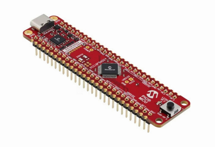
The new PIC18-Q24 microcontrollers are supported by MPLAB Code Configurator (MCC) and the usual ecosystem of development tools for Microchip microcontrollers. Thecompany also provides the PIC18F56Q24 Curiosity NanoEvaluation Kit (EV01E86A) for testing and early software development.

Pricing starts at $1.18 per unit for the PIC18F24Q24-I/STX for orders of 100 pieces or more. The PIC18F56Q24 Curiosity NanoEvaluation Kit can be purchased now for $24.02 on the Microchip Direct website. Further information may be found on the product page and in the press release.
Thanks to TLS for the tip.

Jean-Luc started CNX Software in 2010 as a part-time endeavor, before quitting his job as a software engineering manager, and starting to write daily news, and reviews full time later in 2011.
Support CNX Software! Donate via cryptocurrencies, become a Patron on Patreon, or purchase goods on Amazon or Aliexpress. We also use affiliate links in articles to earn commissions if you make a purchase after clicking on those links.


lots of io, but i think it is time to let 8bit die :p
Especially 8-bit PIC10s, PIC12s, PIC14s, PIC16s & PIC18s. They were outdated 2 decades ago.
I disagree. Such devices can fit various purposes. Their main deficiency is that the vendor didn’t understand that they were not suitable for development without a C compiler.
I used to do quite a bit of 8051 when I was young, this was a CISC CPU with mul, div etc, it was simple and efficient to program in asm. With PIC, the instructions are so poor that everything you’re trying to do makes you think “oh no, I’ll have to open-code this or that right now with the risk of bugs that comes with it”. Mind you that I implemented a sine generator on a 12F508 with freq and amplitude defined by two A/D inputs, it required a multiply and a square operation and that was a big pain, it kept a number of my week-ends busy. The reason for this situation is that Microchip favored their partners who were selling development products. And during this time, Atmel understood that application developers didn’t want to spend their time reinventing the wheel, and as such they needed a compiler, so gcc was made readily available and it became the success we know. I didn’t understand the importance of gcc on AVR until I figured that my sine generator could be reimplemented in 2 hours there. Is the CPU better ? Not at all. It’s quite comparable, it’s just that it comes with a readily available C compiler that works out of the box and that does all the painful stuff for you.
If you compare the PIC10F222 and ATTINY10, both come in SOT23-6, even have the exact same pinout, they have roughly the same specs, and their small size makes them ideal to replace certain low-performance complex logic (e.g. protocol converters, serial signal decoding, implement a delay line etc). In the past I implemented a configurable watchdog using an ATTINY85, but it could also be done using such a device and it would fit anywhere. The difference is that one is developer-friendly and not the other.
And Espressif understood it and didn’t reproduce the same mistake, so they made sure the xtensa compiler was available. So right now you can for example use the arduino IDE to produce code for about all AVRs, for ESP8286 and ESP32, in fact for plenty of devices, but not for PIC since it lacks gcc. The worst here is that it’s probably even not too late for them to catch up, but for what reason would they do that now that they acquired atmel ? After all they now have the best of both worlds with their two competing solutions.