WCH has launched some interesting RISC-V microcontrollers in the last year or so, including the “10 cents” CH32V003 RISC-V microcontroller with 2KB SRAM and 16KB flash or the CH32V307with more resources (up to 64KB SRAM and 256KB flash) and additional peripherals.
So far they were programmable in C language using MounRiver IDE or an open-source toolchain, but WCH has now announced Arduino support for many of those RISC-V microcontrollers which should enable more people to get involved.
The core library for CH32duino works with OpenOCD through WCH-LINKE hardware to download the firmware and debug WCH chips and a riscv-none-embed-gcc toolchain that supports custom RISC-V instructions (half-word and byte compression instruction extensions and hardware stack push/pop functions) found in WCH RISC-V microcontroller.
The following evaluation kits are currently supported with ADC, DAC, USART, GPIO, EXTI, SysTick, I2C, and SPI peripherals:
- CH32V003F4P EVT board
- CH32V203G8U EVT board
- CH32X035G8U EVT board
- CH32V103R8T6_BLACK EVT board
- CH32V307VCT6_BLACK EVT board
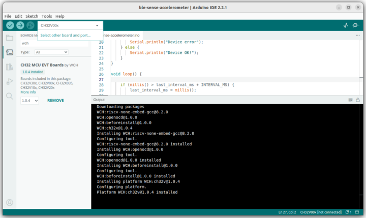
You’ll need to add the following link to the “Additional Boards Managers URLs” field in the Arduino 2.0 IDE: https://github.com/openwch/board_manager_files/raw/main/package_ch32v_index.json, and install CH32 MCU EVT Boards by WCH, and you’ll then be able to select a RISC-V board such as CH32V00x as shown in the screenshot below.
It works with Windows, Linux, and Mac OS with some OS-specific tweaks. You’ll find documentation and source code on the relevant GitHub repository. Those who prefer watching videos can also check out the getting started video embedded below.

Jean-Luc started CNX Software in 2010 as a part-time endeavor, before quitting his job as a software engineering manager, and starting to write daily news, and reviews full time later in 2011.
Support CNX Software! Donate via cryptocurrencies, become a Patron on Patreon, or purchase goods on Amazon or Aliexpress. We also use affiliate links in articles to earn commissions if you make a purchase after clicking on those links.


This should be fun!
Now you got my attention O.O
I am working on the arduino-cli port with Ardulink support and minichlink, inside a docker image:
https://gitlab.com/zoobab/ch32v003-arduino-cli
BTW I was unable to flash 3.3V boards from an Arduino in 5V, i tried a level shifter in between without any success. If someone has a solution…
Can you describe in a bit more detail what you were doing? Were you using a Adruino UNO or something with 5V I/O as a programmer for a 3.3V CH32V003 board? All the other programmers use target Vcc as Vio, IIRC. You say you’ve used a level shifter, but that’s problematic with bidirectional signals like the CH32V003 uses for its program/debug signal.
What worked was flashing a CH32V003 SOP16 soldered to a breakout board in 5V, with an Arduino UNO in 5V.
What did not worked was trying to flash a nanoCh32v003 (which has the SWIO in 3.3V on the PCB) with
1. the same Arduino in 5V, connected to the board on its VCC pin connected to 5V (bypassing the 5V-3.3V voltage regulator)
2. the same Arduino in 5V, but with a bidirectional level shifter to go down from 5V to 3.3V.
I think I should also try a simple resistor to see if does the job.
I am having a look rewriting the Ardulink code in Arduino IDE style, trying to find a way to make the code portable among all the microcontrollers I have, it uses some AVR ASM NOP to have precise timings here:
swio.c · main · Mark / arduino-ch32v003-swio · GitLab
For the nanoCh32v003 case, you have the 5V Vcc of the arduino connected to the 3.3V pin on the nanoCh32v003? I assume that’s how you’re bypassing the regulator. In that case, you’re just programming the CH32V003 as a normal 5V part and it should work just fine. You’re saying that it does not?
The bidirectional level shifter case will be very problematic due to the high speed of the signals involved. You may need to refactor the design to use a dedicated 5->3.3V converter with OE and a separate GPIO on the 5V arduino as an input/sense line of that signal. So, instead of using the OE signal on the GPIO port of the 328, you’ll need to use a GPIO signal to send an OE signal to an external 5V->3.3V converter. Because of that (the converter being unidirectional), you’ll need a third GPIO as a sense line to read the value of the 3.3V SWIO signal. You shouldn’t need a level shifter for that at 3.3V should be sufficient to generate a reasonable high level on the 5V arduino.
Level shifters are very problematic on bidirectional signals and the horrible MOSFET design that is often used for slow speed signals like I2C are not suitable for higher speed signals like this SWIO protocol.
Will retry with some resistors to see if it can do the job from going down from 5V to 3.3V.
This blog lists many possible options:
5V to 3.3V logic level translation/conversion/shifting: how to interface a 5V output to a 3.3V input. – next-hack.com
That blog post is pretty good! Thanks.
CH32V305 not in the list but hopefully can be addded, that one has high speed 480Mbit USB like CH32V307 and is cheaper (with less RAM/flash of course). The Wchlink E JTAG/SWD dongle is based on this chip and is < $3-$4 on aliexpress. May be a successor to Stlink V2 clone dongles.
just perfect.. yooohooo