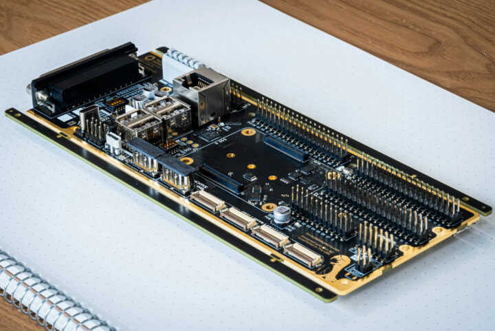
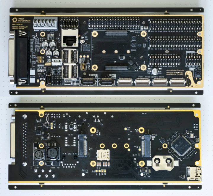
Paisley Microsystems PMC-C-CMX is a DIN-Rail mountable industrial control board taking a Raspberry Pi CM4 or CM5 (once launched), equipped with an STM32H7 Arm Cortex-M7 microcontroller for real-time control.
The carrier board integrates features such as wide voltage input (7 to 55V DC), an M.2 PCIe Gen 3 Key-B and Key-M sockets with cellular option, gigabit Ethernet, HDMI and MIPI DSI display interfaces, twp MIPI CSI camera interfaces, and several headers and connectors with RS485, GPIO, I2S, SPI, and more connected to either the Raspberry Pi Compute Module or the STM32H7 MCU.
Paisley Microsystems PMC-C-CMX specifications:
- Supported system-on-modules – Raspberry Pi CM4 or upcoming Raspberry Pi CM5
- MCU – STMicro STM32H7B0 Arm Cortex-M7 microcontroller up to 280 MHz with 128KB flash, 1.4MB SRAM
- MCU <-> CM communication – UART and/or SPI
- Video Output
- 2x HDMI ports up to 4Kp60
- 2x MIPI DSI connectors
- Camera input – 2x MIPI CSI connectors
- Networking
- Gigabit Ethernet RJ45 port
- Optional WiFi 5 and Bluetooth 5
- Optional 4G LTE via M.2 B-key module and Nano SIM card
- USB – 3x or 4x USB 2.0 ports (3x with popular PCIe B card)
- Serial – RS485 up to 20 Mbps with PROFIBUS-DP support
- Expansion
- 40-pin Raspberry Pi-compatible GPIO header
- M.2 M-Key 2280 socket
- M.2 B-Key 2230/3042/2280 socket with Nano SIM card slot (Note: only one M.2 socket can be used at a time due to Broadcom BCM2711/BCM2712 limitations)
- STM32H7 headers with 70 GPIOs
- 25-pin “modular bus connector”
- I2C, SPI, 8x GPIO
- Power signals – 5V/2A, 3.3V/2A, 2x 6A Vin and 4x GND
- Debugging – Dedicated SWD/ST-LINK interface
- Misc – PCF85063AT RTC
- Power Supply
- 7V to 55V DC up to 10A via 6-pin connector
- 9V/12V/20V up to 100W via USB-C PD port
- Quiescent Power Consumption
- Without Compute Module – 560 mW
- With Raspberry Pi CM4 – 2,200 mW
- Dimensions – 190.5 x 72.0 mm; DIN rail compatible
- Temperature Range – -30 to +80°C
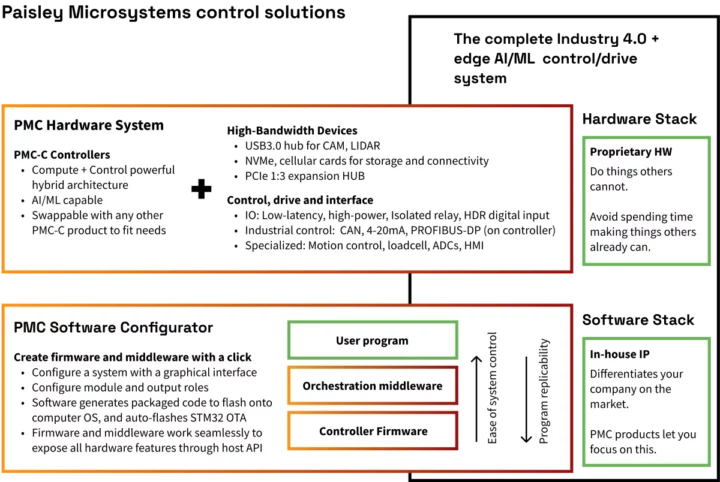
The Raspberry Pi CM4/CM runs Linux (Raspberry Pi OS) with logic/control/driving code and a hardware control middleware while the STM32H7 microcontroller runs C or ASM code to control GPIOs in real-time and communicate with the Compute Module over UART or SPI. A simple device control library, the middleware, and STM32H7 firmware will be provided by the company so that customers can focus on the higher-level parts of the software. At this time, I could not find much in the way of publicly available software documentation, but there are more details about the hardware on the documentation website.

Paisley Microsystems sells the PMC-C-CMX industrial control board for Raspberry Pi CM4/CM5 for $149.99 including shipping (at least in the US).

Jean-Luc started CNX Software in 2010 as a part-time endeavor, before quitting his job as a software engineering manager, and starting to write daily news, and reviews full time later in 2011.
Support CNX Software! Donate via cryptocurrencies, become a Patron on Patreon, or purchase goods on Amazon or Aliexpress. We also use affiliate links in articles to earn commissions if you make a purchase after clicking on those links.


So this confirms that the RPi CM5 will definitely be compatible with existing CM4 carrier boards?
Raspberry Pi shared a Raspberry Pi CM5 document a while ago (NDA required, so I did not sign and access it). It’s likely not all CM4 carrier boards will work with CM5, but companies that want to design CM4 and CM5-compatible carrier boards can do so.
The board is designed and tested to be fully compliant with PCIe Gen 3.0 (8GT/s) rather than the PCIe 2.0 carried by other boards.
It is known that future CM-form factor SoMs will implement these faster generation signals and the chipsets used are all fully compatible with the PCI-SIG G3 spec.
Single lane only? What about RGMII signals?
BCM2712 seems to have a spare PCIe lane and an integrated MAC…
Unfortunately the 200-pin connector only exposes the four MIPI interfaces, two HDMI and one PCIe lane. A packet-switch module is in development to allow three peripherals to branch off from the single Gen 3.0 8GT lane.
We don’t expect the PCI bus bandwidth to bottleneck a system running on the BCM chip, even with SSD and USB3 interfaces simultaneously connected.
> We don’t expect the PCI bus bandwidth to bottleneck a system running on the BCM chip,
Hmmm strange, given that I’m pulling 19Gbps of HTTP traffic out of a quad-A72 Armada8040, I think that CPU-wise, 8Gbps is definitely within reach for a relatively similar set of CPU cores in the CM4. Of course the rest of the I/O B/W is not great on the BCM SoC but it’s a bit sad they’re sacrificing the rare I/Os available on the chip.
Anyway, nice that you implement a PCIe switch, that’s definitely the way to go for modern SoCs so that lanes are no longer dedicated to a single low-bandwidth chip!
Seems kinda weird to use RP4/5 for this. There are SoCs with MCUs embedded which would reduce component cost or other advantages.
I don’t see why specifically use Raspberry Pis for this.
Raspberry Pi platform was chosen for this embedded controller as opposed to other linux/risc-based SoCs largely for its comprehensive documentation and wide implementation. Ease of use for the engineer who has twenty other things to do!
The PMC controller series are designed with IO and expandability in mind, featuring plug-and-play modules to fulfill nearly any electrical control task. A readily-made solution to interface with systems as opposed to SBC with a lesser IO interface that developers must design and debug their own hardware for.
I understand that does make sense and it is a pretty cool thing. It’s just me really wondering because from what I know about the BCM chips, it’s only really their peripherals documentation that is open source.
Of course, the STM32H7 will be the one doing the real time jobs but at the same time, it leaves me wondering if something like a NXP i.MX93/95 or a TI SoC that has integrated Real Time cores.
Which also makes me ask a question to you, is the SPI(or UART) communication with the MCU ever a bottleneck? The BCM can run a pretty high SPI clock, but high SPI clocks are hard to design PCBs around and since a lot of IO could be driven through, it seems like the SPI connection could end up delaying things.
Certainly not an issue for most designs but thinking of ones where it could run the ADCs of the STM32H7 at high sampling rates with lots of interrupts in the GPIO or etc.
Just something I am curious about, so if I say wrong out of ignorance, ignore that.
Thank you for the reply!
We have designed the SPI/UART/other LSI signal lines to pass driver/receiver crosstalk or ringing specs at up to 0.25GHz. This is definitely overkill with the max SPI speed of 10-100MHz for many devices.
In testing which we completed recently for LSI validation, we were able to run SPI clocked at 82MHz in a loopback test through five!!! daisy chained IO modules, dropping 0 out of (4096 x 1024) Bytes. We will definitely also do real-world IO latency tests with our IO modules, as well as EEPROM tests.
Our datasheet actually needs to be updated since it specifies an incorrect 24MHz max SPI speed, which is the max speed for the Chip Select buffer, not the TMUX1574 used for the data signals (2GHz theoretical).
The STM32H7 is treated primarily as a real-time reactionary node and fast GPIO expander – honestly not doing much justice to the vast array of peripherals the H7 series supports. However as opposed to a cost-minimizing consumer application, we want to make sure the embedded processor never presents a speed bottleneck for critical GPIO use cases. For example, I have colleagues who had trouble reading from step-based encoders with the BCM IO. Implementing bare IO/LSI signal interface options with a capable STM32 seemed like a great choice to make the controller truly complete.
We recognize that firmware development for embedded processors is not an easy task, so we are working hard on configuration software to directly generate firmware to interface with our functional modules as well as open-protocols.
We will decrease the hassle of writing UART interfaces, device initiation needed to write to a SPI device on the STM with a function call in Python or C running on the Pi to just a single library import and method call. We will also enable virtually no-code physical interfacing even in complex environments such as OTA Docker-Python deployment; paving the way to the future with ML/AI-in-the-loop systems control with compute capabilities at the edge.
I may have rambled quite a lot on our product: From even just a purely aesthetic perspective we are quite proud of it! If you are interested please do contact me and we will happily give more technical details or hook you up with sales 🙂
Email: matthew@paisleymicro.com
That is really cool and seems like a very useful product to a lot of industrial applications. Unfortunately, I am just a hobbyist, so this is out of my reach.
I believe that the maximum SPI frequency of the BCM2711(RPi4) is 250 MHz(which is the APB clock), right? Which is what you guys designed it for.
This has nothing to do with the product in question but one of the things that I am not a fan of RPs is that I have no idea what oscillators go to what clocks and what is really in each clock domain.
Like this guy:
https://raspberrypi.stackexchange.com/questions/3400/does-overclocking-affect-the-spi-apb-clock
Nobody seemed to have an official documentation as the peripheral datasheet only mentions the prescalers/frequency dividers for the peripherals.
Having more control over that due to the fact that your peripherals are in a MCU seems like a very good potential fix though.