
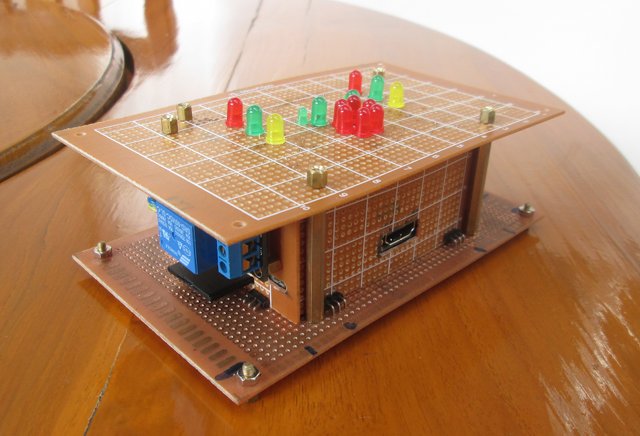
Following up my previous post entitled “DIY Modular Stripboard / Perfboard Casing for Raspberry Pi (Part 1)” where I explained how I created an modular enclosure made of perfboard, or the overall concept, I’ve now designed two “smart” sides for the enclosure: a 16-LED stripboard side, and a 5V relay stripboard side. Today, I’ll detail how I’ve done this, with details about electronics, soldering, assembly, the Linux distribution (built with Yocto), as well C programs, HTML page, and (CGI) shell scripts used to light up the 16 LEDs, and control a standard 220V lamp with a relay via my phone’s web browser.
16-LED Stripboard Top Schematics, Soldering, and Testing
I had decided to design the top board of the enclosure with several LEDs, 3 LEDs on both side, and a Raspberry fruit (6 red LED) and 2 leaves (4 green LED) in the middle. Before getting started, I did some experiment on a breadboard, and quickly discovered that 5V LEDs can’t simply be put in series (2 LEDs require 10V, 6 LEDs 30V and so on), so I had to connect them in parallel with a resistor for each. My initial plan was actually to use 11 LEDs in series just for the Raspberry, which I scaled down to 6 LEDS in parallel due to lack of space.
Finally, I went with the schematics below, drawn for the purpose of this blog post, with Kicad in Ubuntu.
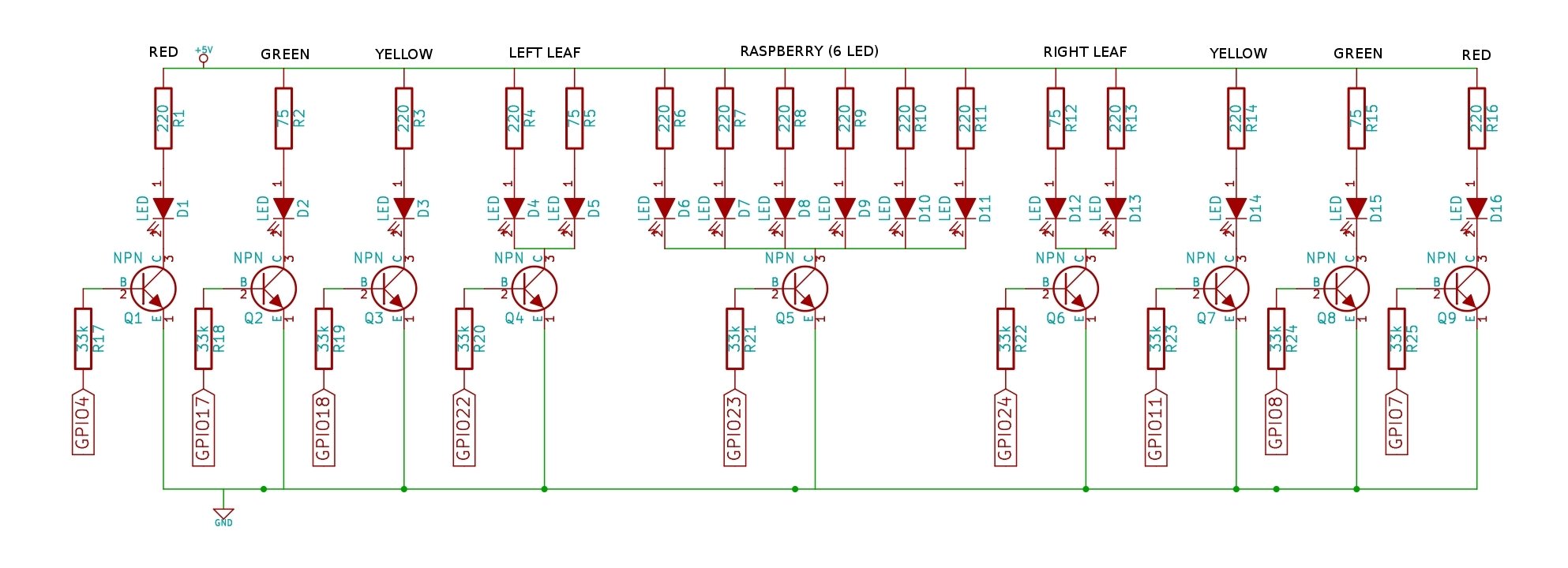
Since the LED are 5V, and Raspberry Pi GPIO output 3.3V, you need a transistor to handle voltage difference. The transistor base resistor is to limit the GPIO current (33k Ohm resistors worked for me), and I selected the LED resistors based on breadboard trial and error. 220 Ohm seemed good for red and yellow LEDs, as well as small green LED, but I had to with 75 Ohm resistors for the green LEDs, as they were just too dim with 220 Ohm resistor.
I bought my components from dx.com and ebay:
- 50x 2N2222 NPN Transistors – $1.13
- 5x Perfboards – $6.60
- 100x 5V LEDs (Green/Red/Yellow) – $4.60
- 2500x resistors with different resistances – $17.60 (I think I may now have enough resistors for the rest of my life…)
- 40x 30cm breadboard wires – $4.90
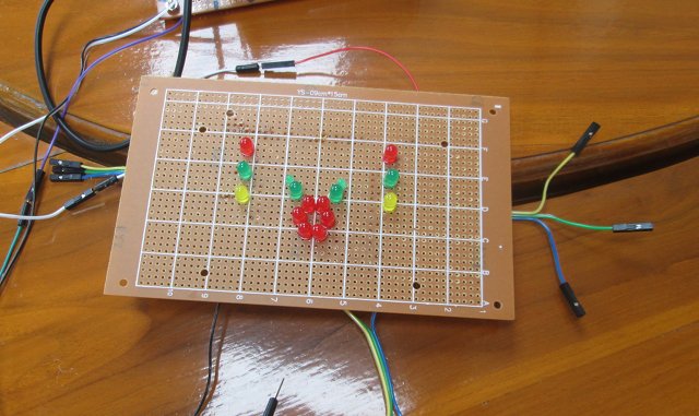
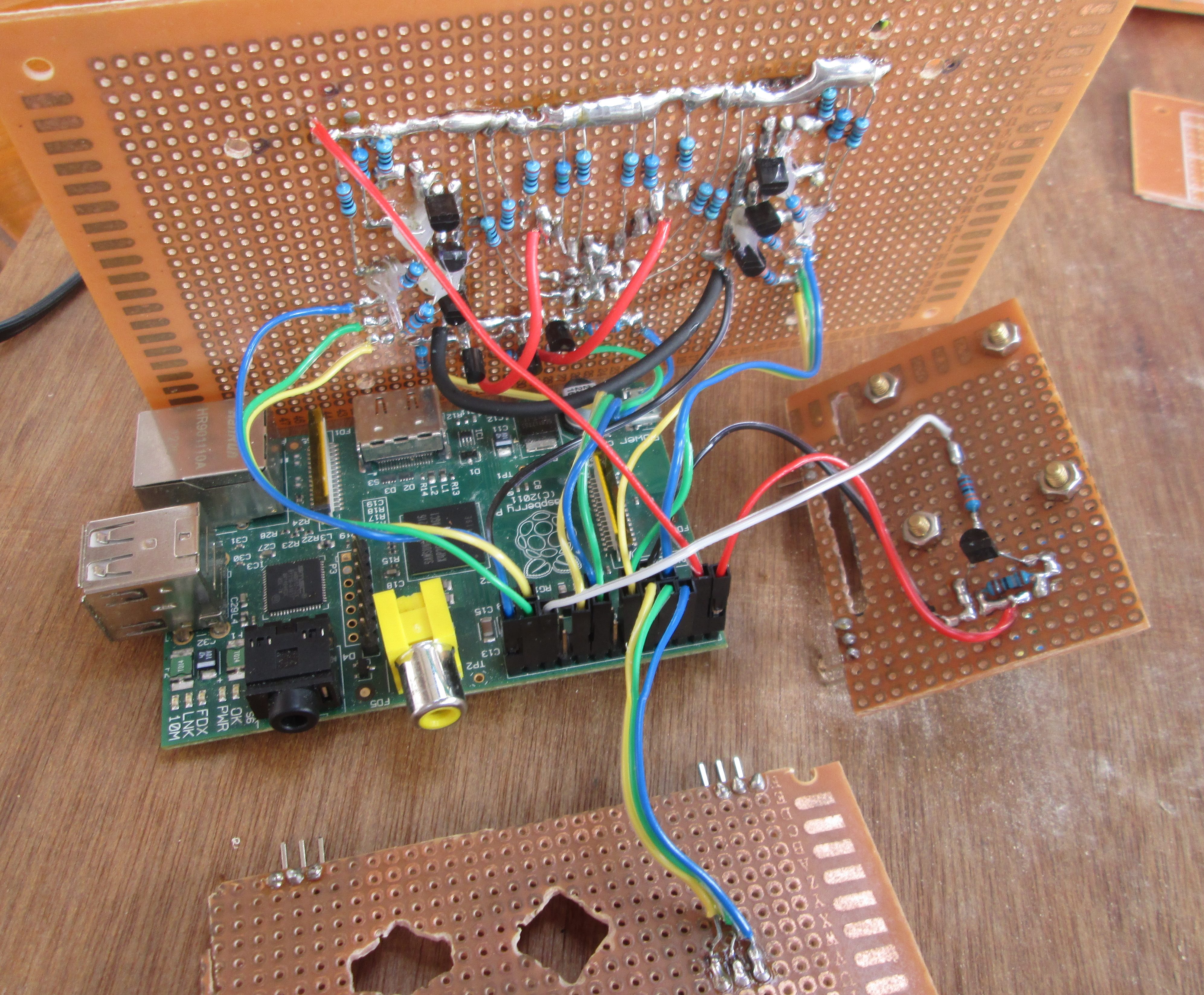
I decided to only show the LED on the top of the board, and solder all other components on the other side. You just need plier to cut the components wire leads as close as possible from the stripboard surface.
 I started soldering the 5V line, and you can see I struggled a bit at that stage to connect the soldering pad. Finally, I found out I had to remove the soldering iron quickly, as soon as the solder was melt on 2 adjacent pads, and the rest of the board looks a little better.
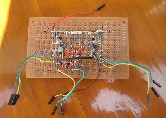
Before testing it, you’d better check, and even double check, the connections with a multimeter, or you may damage your Raspberry Pi if something goes wrong. I connected 5V and GND to the 26-pin header of the Raspberry Pi, as well as the 3.3V pin to test the 9 inputs (and 16 LEDs). Once I confirmed everything worked, I used a glue gun to add isolation between parts that present a risk a short-circuit.
Relay Stripboard Side Schematics, Soldering, and Testing
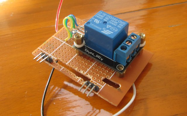
I bought a cheap relay module for Arduino ($2.40) to add the side SD card / power supply side of the Raspberry Pi case.

I adapter the schematics above from susa.net, as I did not need the extra D1 diode as it is already part of the relay board. Instead of BC337 transistor, I used 2N2222 with a 33 kOhm transistor base resistor. I also threw caution out of the window, as I connected 220V load, but more on that later.
Compared to the LED board, soldering was child play.
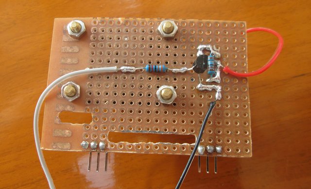
I used 7 stand offs to fasten the relay board to my perfboard, adding some screw isolation caps, as the 3 stand-offs screw at the top were too long. The 3 pins on the left of the picture below are + (Connected to 5V), – (Connected to Ground), and S (connected to GPIO 25 on RPi). On the right you are three pins of the load with COMMON in the middle, NC (Normal Close contact) and NO (Normal Open contact) on the sides. If you want your device to be ON by default, connect NC and COMMON, otherwise NO and COMMON.
As with the LED board, I checked the connection with a multimeter first, and then with a breadboard. Since using 220V with a breadboard would be suicidal, I decided to use a 5V LED for testing instead, using the connection diagram from openhomeautomation.net.
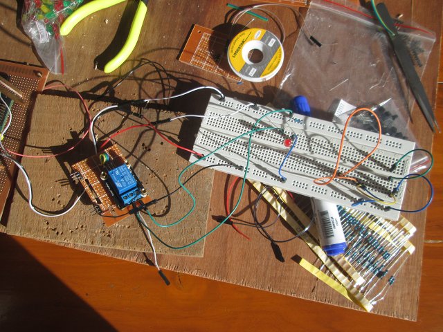
It worked fine, so it was time to move on to the enclosure assembly.
Raspberry Pi Modular Enclosure Connection and Assembly
I actually have 3 “smart” sides: the LED top board, the relay board, and the board to access the serial console.
The LED board requires +5V and GND, and the 9 GPIO pins listed in the schematics. The relay board requires two other 5V and GND pins, as well as GPIO 25, and the serial port board is connected to Tx/Rx and GND. All cables are connected to P1 pin-header on the Raspberry Pi.
After checking, and double checking the connections, I could just fasten the different pieces together, as I did previously when there were not circuit on the perfboards.
The last step before moving to software was to connect an interesting load. I figured out the easiest way was probably to just connect a lamp, and disassemble the lamp switch.
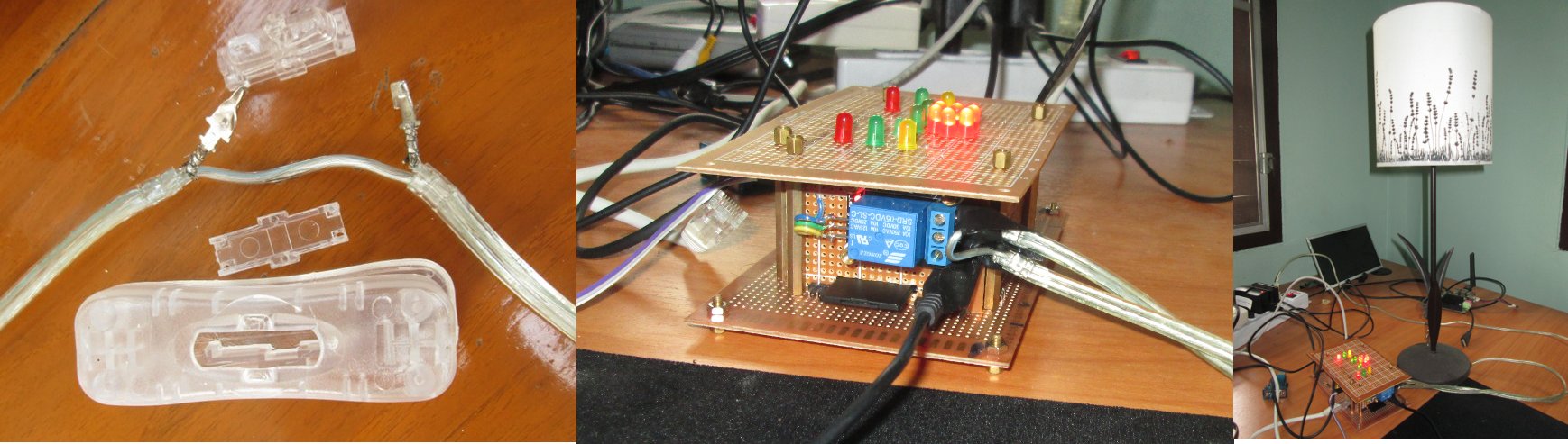
To avoid a short-circuit between the 2 parts of the cable, I used the most commonly used insulator in Thailand: Black tape.
Software – Linux, Controlling LEDs with GPIO and the Relay with a Web page.
There are already many instructions available to control Raspberry Pi’s GPIO, setup a web server, etc… But I added a little challenge to my setup by using a 256MB SD card. That means Raspbian cannot be installed, you have to cross-compile your program, as there’s not enough space to install the GCC toolchain, and you can’t use web servers like Apache2 or nginx either. That may look like self-inflicted unnecessary pain, but it’s a nice training exercise, as it’s much closer to what engineers actually use to develop networked embedded devices.
Since I can’t use Raspbian, I’ve decided to use a minimal image built with Yocto instead. I’ve already written the instructions to use Yocto for Raspberry Pi previously, but I won’t use the exact Yocto image I generated in that post, as I’ll have to enable more options in busybox.
We can’t build anything directly on the Raspberry Pi, so we need to find a cross-toolchain. The good news is that Yocto already made one for us (and itself) which you can find in ./poky/build/tmp/sysroots/x86_64-linux/usr/bin/armv6-vfp-poky-linux-gnueabi/ directory.
Let’s add it to our path:
|
1 |
export PATH=$PATH:/home/jaufranc/edev/rpi/yocto/poky/build/tmp/sysroots/x86_64-linux/usr/bin/armv6-vfp-poky-linux-gnueabi/ |
I’ll use bcm2835 library to control the GPIOs, so let’s download, build, and install it to ~/edev/rpi/gpio directory:
|
1 2 3 4 5 6 7 8 9 |
cd ~/edev/rpi mkdir gpio cd gpio wget http://www.airspayce.com/mikem/bcm2835/bcm2835-1.26.tar.gz tar xzvf bcm2835-1.26.tar.gz cd bcm2835-1.26/ ./configure --target=arm-poky-linux-gnueabi- --host=arm-poky-linux-gnueabi --prefix=/home/jaufranc/edev/rpi/gpio make make install |
I’ve written two simple C programs:
- gpio_out.c – Use to set a GPIO pin high or low. Usage: ./gpio_out [pin] [value]. I’ll use it to control the relay.
|
1 2 3 4 5 6 7 8 9 10 11 12 13 14 15 16 17 18 19 20 21 22 23 24 |
#include #include "bcm2835.h" int main(int argc, char **argv) { int gpiopin, gpiovalue; if (argc != 3) { printf("Usage gpioout pin value\n"); return 1; } gpiopin = atoi(argv[1]); gpiovalue = atoi(argv[2]); /* Init bcm2835 library */ if (!bcm2835_init()) return 1; /* Set the pin to be an output */ bcm2835_gpio_fsel(gpiopin, BCM2835_GPIO_FSEL_OUTP); bcm2835_gpio_write(gpiopin, gpiovalue); printf("Set pin %d to %s\n", gpiopin, gpiovalue?"HIGH":"LOW"); bcm2835_close(); return 0; } |
- stripboardled.c – A loop to lit the 16 LEDs on the top board in a fancy way
|
1 2 3 4 5 6 7 8 9 10 11 12 13 14 15 16 17 18 19 20 21 22 23 24 25 26 27 28 29 30 31 32 33 34 35 36 37 38 39 40 41 42 43 44 45 46 47 48 49 50 51 52 53 54 55 56 57 58 59 60 61 62 63 64 65 66 67 68 69 70 71 72 73 74 75 76 77 78 79 80 81 82 83 84 85 86 87 88 89 90 91 92 93 94 95 96 97 98 99 100 101 102 103 104 105 106 107 108 109 110 111 112 113 114 115 116 117 118 119 120 121 122 123 124 125 126 127 128 |
/* stripboardled.c * * Demo program for LED stripboard top * */ #include #include "bcm2835.h" #define LED_RED_LEFT 4 #define LED_RED_RIGHT 7 #define LED_GREEN_LEFT 17 #define LED_GREEN_RIGHT 8 #define LED_YELLOW_LEFT 18 #define LED_YELLOW_RIGHT 11 #define LED_LEAF_LEFT 22 #define LED_LEAF_RIGHT 24 #define LED_RASPBERRYPI 23 void ledconfig () { /* Set all pins to output mode */ bcm2835_gpio_fsel(LED_RED_LEFT, BCM2835_GPIO_FSEL_OUTP); bcm2835_gpio_fsel(LED_RED_RIGHT, BCM2835_GPIO_FSEL_OUTP); bcm2835_gpio_fsel(LED_GREEN_LEFT, BCM2835_GPIO_FSEL_OUTP); bcm2835_gpio_fsel(LED_GREEN_RIGHT, BCM2835_GPIO_FSEL_OUTP); bcm2835_gpio_fsel(LED_YELLOW_LEFT, BCM2835_GPIO_FSEL_OUTP); bcm2835_gpio_fsel(LED_YELLOW_RIGHT, BCM2835_GPIO_FSEL_OUTP); bcm2835_gpio_fsel(LED_LEAF_LEFT, BCM2835_GPIO_FSEL_OUTP); bcm2835_gpio_fsel(LED_LEAF_RIGHT, BCM2835_GPIO_FSEL_OUTP); bcm2835_gpio_fsel(LED_RASPBERRYPI, BCM2835_GPIO_FSEL_OUTP); } void ledson () { bcm2835_gpio_write(LED_RED_LEFT, HIGH); bcm2835_gpio_write(LED_RED_RIGHT, HIGH); bcm2835_gpio_write(LED_GREEN_LEFT, HIGH); bcm2835_gpio_write(LED_GREEN_RIGHT, HIGH); bcm2835_gpio_write(LED_YELLOW_LEFT, HIGH); bcm2835_gpio_write(LED_YELLOW_RIGHT, HIGH); bcm2835_gpio_write(LED_LEAF_LEFT, HIGH); bcm2835_gpio_write(LED_LEAF_RIGHT, HIGH); bcm2835_gpio_write(LED_RASPBERRYPI, HIGH); } void ledsoff() { bcm2835_gpio_write(LED_RED_LEFT, LOW); bcm2835_gpio_write(LED_RED_RIGHT, LOW); bcm2835_gpio_write(LED_GREEN_LEFT, LOW); bcm2835_gpio_write(LED_GREEN_RIGHT, LOW); bcm2835_gpio_write(LED_YELLOW_LEFT, LOW); bcm2835_gpio_write(LED_YELLOW_RIGHT, LOW); bcm2835_gpio_write(LED_LEAF_LEFT, LOW); bcm2835_gpio_write(LED_LEAF_RIGHT, LOW); bcm2835_gpio_write(LED_RASPBERRYPI, LOW); } int main(int argc, char **argv) { /* Init bcm2835 library */ if (!bcm2835_init()) return 1; /* configure LED gpios to output mode */ ledconfig(); /* demo loop */ while (1) { int i=0; /* turn off all LEDs, and wait 1 second*/ ledsoff(); bcm2835_delay(1000); ledson(); bcm2835_delay(500); ledsoff(); bcm2835_delay(500); ledson(); bcm2835_delay(500); ledsoff(); bcm2835_delay(500); bcm2835_gpio_write(LED_RED_LEFT, HIGH); bcm2835_gpio_write(LED_RED_RIGHT, HIGH); bcm2835_delay(500); bcm2835_gpio_write(LED_GREEN_LEFT, HIGH); bcm2835_gpio_write(LED_GREEN_RIGHT, HIGH); bcm2835_delay(500); bcm2835_gpio_write(LED_YELLOW_LEFT, HIGH); bcm2835_gpio_write(LED_YELLOW_RIGHT, HIGH); bcm2835_delay(500); bcm2835_gpio_write(LED_LEAF_LEFT, HIGH); bcm2835_gpio_write(LED_LEAF_RIGHT, HIGH); bcm2835_gpio_write(LED_RASPBERRYPI, HIGH); bcm2835_delay(1000); ledsoff(); bcm2835_delay(500); bcm2835_gpio_write(LED_RED_LEFT, HIGH); bcm2835_gpio_write(LED_YELLOW_RIGHT, HIGH); bcm2835_delay(500); bcm2835_gpio_write(LED_RED_LEFT, LOW); bcm2835_gpio_write(LED_YELLOW_RIGHT, LOW); bcm2835_gpio_write(LED_GREEN_LEFT, HIGH); bcm2835_gpio_write(LED_GREEN_RIGHT, HIGH); bcm2835_delay(500); bcm2835_gpio_write(LED_GREEN_LEFT, LOW); bcm2835_gpio_write(LED_GREEN_RIGHT, LOW); bcm2835_gpio_write(LED_RED_RIGHT, HIGH); bcm2835_gpio_write(LED_YELLOW_LEFT, HIGH); bcm2835_delay(500); ledsoff(); bcm2835_delay(200); for(i=0;i<5;i++) { bcm2835_gpio_write(LED_LEAF_LEFT, HIGH); bcm2835_gpio_write(LED_LEAF_RIGHT, LOW); bcm2835_gpio_write(LED_RASPBERRYPI, LOW); bcm2835_delay(250); bcm2835_gpio_write(LED_LEAF_LEFT, LOW); bcm2835_gpio_write(LED_LEAF_RIGHT, HIGH); bcm2835_gpio_write(LED_RASPBERRYPI, LOW); bcm2835_delay(250); bcm2835_gpio_write(LED_LEAF_LEFT, LOW); bcm2835_gpio_write(LED_LEAF_RIGHT, LOW); bcm2835_gpio_write(LED_RASPBERRYPI, HIGH); bcm2835_delay(250); } } bcm2835_close(); return 0; } |
Let’s cross-compile then in ~/edev/rpi/gpio directory:
|
1 2 |
arm-poky-linux-gnueabi-gcc gpio_out.c -o gpio_out -I./include -L./lib -lbcm2835 arm-poky-linux-gnueabi-gcc stripboardled.c -o stripboardled -I./include -L./lib -lbcm2835 |
We’ve now got the binary in our Linux PC. A typical way to exchange files between the target device and the build machine is to use an NFS server:
|
1 2 3 |
sudo mkdir /srv/nfs sudo chown jaufranc.jaufranc /srv/nfs sudo vi /etc/exports |
Then edit /etc/exports as root (sudo) and add the line:
|
1 |
/srv/nfs 192.168.0.0/24(rw,no_root_squash,async,no_subtree_check) |
Now access the Raspberry Pi board via the serial console, SSH or an HDMI display, and mount the NFS share:
|
1 2 |
mkdir /mnt/nfs mount -t nfs -o nolock 192.168.0.105:/srv/nfs /mnt/nfs |
Copy the programs in the Linux computer to the NFS share:
|
1 2 |
cp stripboardled /srv/nfs cp gpio_out /srv/nfs |
We can try those in the Raspberry Pi to flash the LEDs, and turn on the light connected to the relay:
|
1 2 3 |
cd /mnt/nfs/ ./stripboardled & ./gpio_out 25 1 |
There’s no http server in the minimal Yocto image, and since our needs are limited (html + cgi), I’ll enabled httpd in busybox. Referring to the post Image for Raspberry Pi using the Yocto Project, we’ll need to configure busybox, enable httpd with CGI support, and rebuild the image:
|
1 2 3 4 |
bitbake busybox -c menuconfig <a href="http://www.cnx-software.com/wp-content/uploads/2013/07/Busybox_HTTPD_CGI.jpg"><img class="aligncenter wp-image-11767" src="http://www.cnx-software.com/wp-content/uploads/2013/07/Busybox_HTTPD_CGI.jpg" alt="Busybox_HTTPD_CGI" width="619" height="395" /></a> bitbake busybox bitbake rpi-basic-image |
Let’s copy the image to the SD card, boot the Raspberry Pi, and create the necessary files in the board to control the relay.
- /www/light.htm – An HTML form with On/Off buttons (See code)
- /www/cgi-bin/lighton – Shell script to turn on the relay (See code)
- /www/cgi-bin/lightoff – Shell script to turn off the relay (See code)
lighton/off shell scripts are ugly hacks that call /usr/sbin/gpio_out, and reaload light.htm with a redirect. There’s certainly a better way to do this with HTML + CGI, but it works…
We also need to copy the “GPIO” binaries to /usr/sbin in the Raspberry Pi, and set the permission for the scripts:
|
1 2 3 4 |
cp /mnt/nfs/stripboardled /usr/sbin cp /mnt/nfs/gpio_out /usr/sbin chmod +x /www/cgi-bin/lighton chmod +x /www/cgi-bin/lightoff |
Since I wanted the system to automatically, I’ve added the following line at the end of /etc/inittab:
|
1 |
2:2345:respawn:/usr/sbin/rpi.sh |
and created /usr/sbin/rpi.sh to start the http server, and the LED demo program:
|
1 2 3 |
#!/bin/sh httpd -h /www /usr/sbin/stripboardled |
Finally, set the permission for rpi.sh, and restart the board:
|
1 2 3 |
chmod +x /usr/sbin/rpi.sh sync reboot |
The LED should start to blink after a few seconds, and you should be ableto turn on/off the light bulb with a web browser, as shown in the demo below.

Jean-Luc started CNX Software in 2010 as a part-time endeavor, before quitting his job as a software engineering manager, and starting to write daily news, and reviews full time later in 2011.
Support CNX Software! Donate via cryptocurrencies, become a Patron on Patreon, or purchase goods on Amazon or Aliexpress