
Telnet and SSH are great to access a Linux device, machine and computer remotely when they are already running, but when you are working on the bootloader and/or kernel themselves, you’ll have to use a serial port to access the terminal / serial console. Boards used to get an RS232 port which you connected to your computer with a NULL modem cable, but these days, most boards and devices expose TTL signals and require a USB to TTL debug board to access the console via a USB cable. If you only have one device close to you computer that’s fine, but if your testbed is a little further. or you need to access the serial console on multiple boards you could consider using ESP8266 module to export the terminal over WiFi.
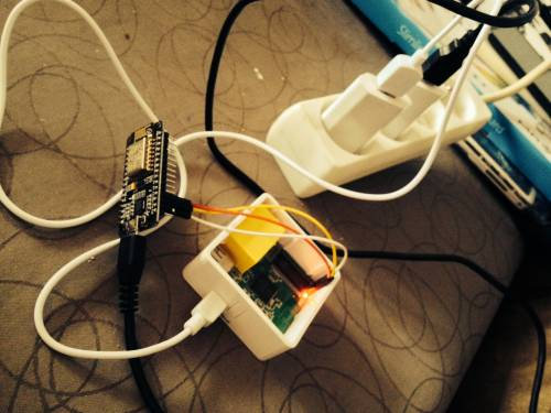 This is exactly what Zoobab did above with a GL.inet router running OpenWRT and NodeMCU board with ESP-12(E) module based on Espressif ESP8266 WiSoC. The wireless module is powered by a mico USB cable, and its GND, TX, and RX pins are connected to the corresponding router’s pins. Both works at 3.3V so no voltage conversion is needed, but with some other hardware it may be necessary to convert 5V to 3.3V.
The next step is to flash NodeMCU with ESP-LINK firmware, which connects an attached MCU to the Internet using an ESP8266 Wifi module. Now you can access the router terminal via ESP8266 board web interface.
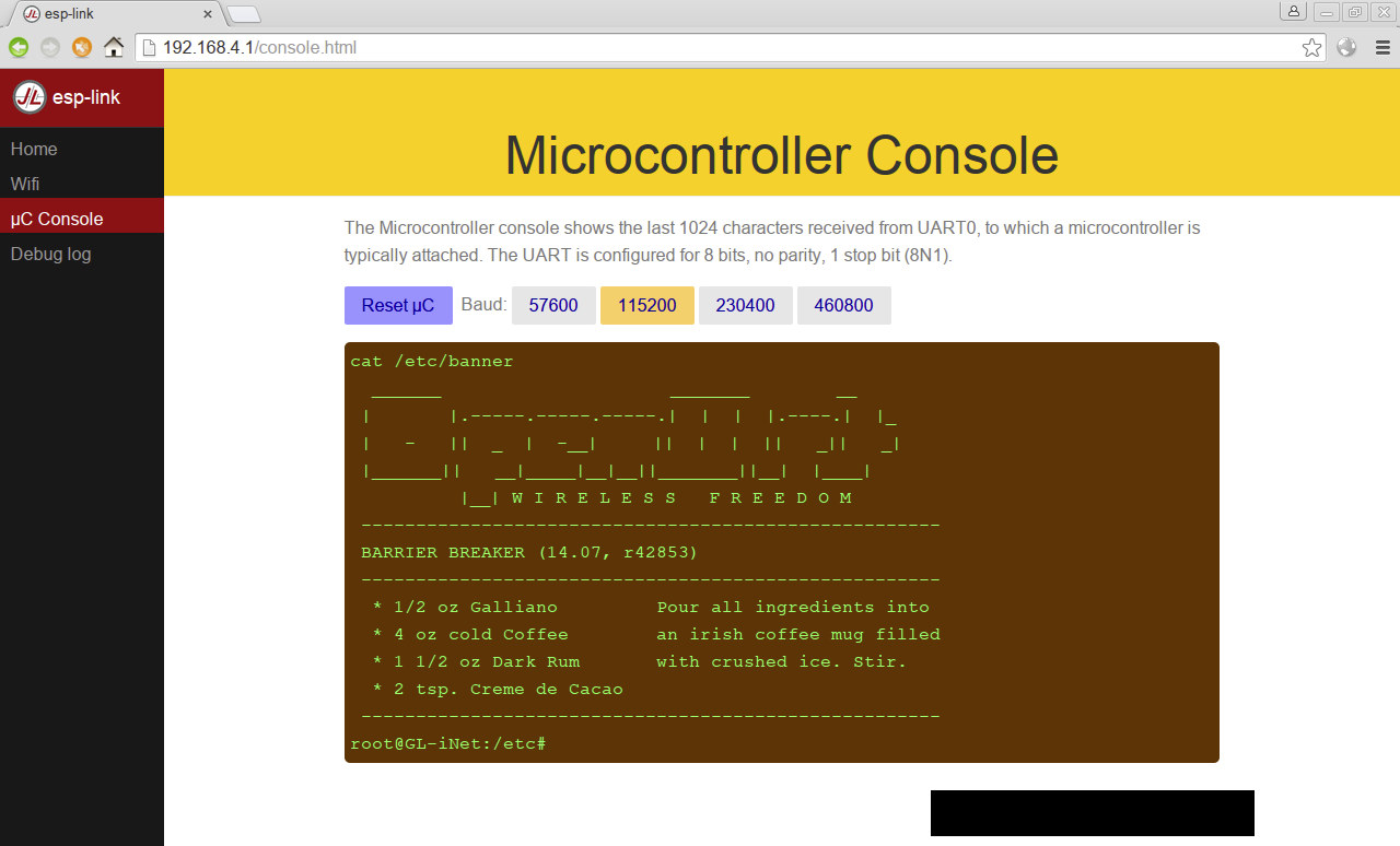
That’s great with a little, or maybe not so little, caveat: it’s read-only. So if you want to input text in the serial console, you’ll currently have to telnet to your ESP8266 board to access the router’s serial console.
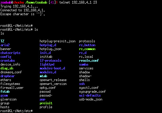 The implementation is still work in progress, as more complete documentation must be written, more features are planned (web console input, https console, etc…), and a few bugs still persist such as Ctrl+C not working with telnet. To work around the latter you can use Putty or socat, which can also allows to upload files over the serial link using Serio Python script.

Jean-Luc started CNX Software in 2010 as a part-time endeavor, before quitting his job as a software engineering manager, and starting to write daily news, and reviews full time later in 2011.
Support CNX Software! Donate via cryptocurrencies, become a Patron on Patreon, or purchase goods on Amazon or Aliexpress


I’ve also asked Zoobab about some more use cases:
The glinet router has also a 3 pins connector (RX, TX and GND), and the VCC 3.3V is on another connector. So it would be possible to power the ESP without an external USB power supply. I have to solder one pin on the Glinet to expose the hole as a male pin.
For the CTRL-C issue, there is a way to put telnet in “character mode”, you need to have a .telnetrc which has this:
$ cat .telnetrc
192.168.0.10
mode character
Just found the solution here: http://unix.stackexchange.com/questions/224735/telnet-why-application-doesnt-read-telnetrc
If someone has any ideas on which chip to use to connect multiple TTL serial ports, and to switch between them. I would suspect this kind of chip to be configurable via I2C or similar.
@zoobab
I guess a CPLD could be a used for this, but there’s probably a cheaper / simpler solution.
@cnxsoft
Maybe analog multiplexer switch like ADG726 could be used. That one could control 16 UARTs: http://www.analog.com/en/products/switches-multiplexers/analog-switches-multiplexers/adg726.html.
That’s a $10 part @ http://www.mouser.com/Analog-Devices-Inc/Semiconductors/Switch-ICs/Multiplexer-Switch-ICs/ADG726-Series/_/N-7590d?P=1yygvi2Z1yyh4l4
No DIP version however.
More options @ http://www.analog.com/en/products/switches-multiplexers/analog-switches-multiplexers/dual-supply-25v.html
This was suggested @ http://electronics.stackexchange.com/questions/32582/switching-multiplexing-rs232-signal-lines for RS232, but I assume the same principal should work for UART too.
74HC4052 looks like a cheaper solution and DIP.
http://www.nxp.com/documents/data_sheet/74HC_HCT4052.pdf
$4.20 on eBay for 10 pieces
http://www.ebay.com/itm/10PCS-74HC4052-DIP-DIP-16-TI-4-CHANNEL-MULTIPLEXER-IC-TEXAS-/251095787854