
Since ESP8266 is now so popular, I’ve recently bought a NodeMCU board to try it. I selected this board because the latest version of the board is breadboard-friendly, integrates a USB to serial chip, and it can be powered by a simple USB to micro USB cable. I also noticed a ESP8266 tutorial with NodeMCU firmware by SwitchDoc Labs the other day (using ESP-12 and Adafruit Huzzah), which I applied to my NodeMCU board, but since I encountered a few issues, I decided to report my findings, and write my own little getting started guide to switch on/off LED and GPIOs using a web interface.
NodeMCU v0.9 and NodeMCU v1.0
If you are going to purchase a NodeMCU board it’s important to know there are two official versions:
- NodeMCU v0.9 with ESP-12 module
- NodeMCU v1.0 with ESP-12E module
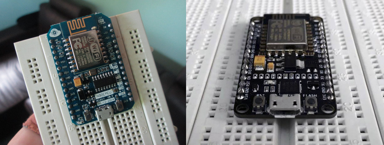
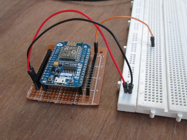
The main complain about NodeMCU v0.9 is that while it fits on the breadboard, you can’t use as it takes the full width of the board, while NodeMCU v1.0 is really breadboard-friendly as you can see on the right part of the picture above.
I’ve bought mine for just above $6 on eBay advertised as “NEW Version NodeMcu Lua ESP8266 WIFI Internet Development Board Latest Firmware”. The image was still v0.9, but since there are only two version, I was sort of expecting to receive NodeMCU v1.0. I was wrong…
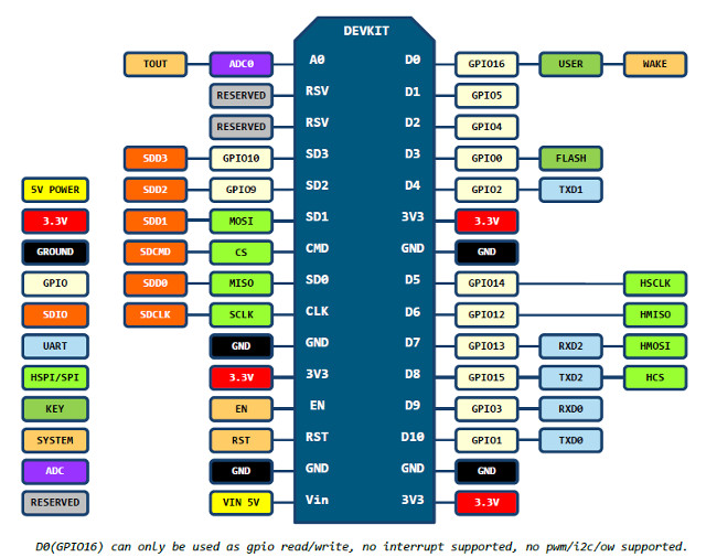
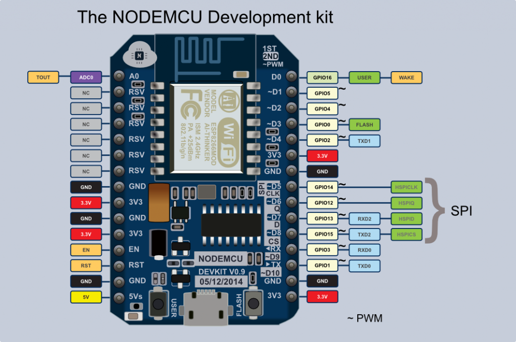
Other differences are that NodeMCU v1.0 has some extra GPIOs. Please find the pinout for both versions below. We’ll use these a little later in this tutorial.
Using NodeMCU v0.9 with a Breadboard
If you are lucky (or smart) enough to have purchased a NodeMCU v1.0 board, you can skip this section, but if you are stuck with NodeMCU v0.9 this may be useful.
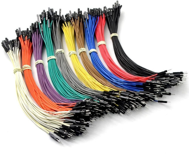
The first way is to connect the board to the breadboard using female to male Dupont cables.
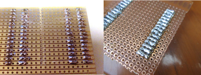
This works, but it’s not quite a neat as the solution provided on lucstechblog, that is making an adapter board with four female headers allowing to insert NodeMCU v0.9 board, and connecting male Dupont cables to the breadboard.
 Luc uses a stripboard, which makes it quite easier to solder than the perfboard I used, and it took me a little while to get rid of some shortcuts I did during soldering. So I should get myself some stripboards too, as they may be useful in the future.
Installing Firmware and Accessing the Console on NodeMCU
Now that we have taken care of the hardware part, let’s check how to actually use the board. I was expecting some easy to follow documentation, but the documentation on NodeMCU.com is not really that useful to get started, and after searching further I eventually ended up on NodeMCU Firmware Wiki on github which provides more details.
However, after connecting the board to my computer via a micro USB to USB cable, while I could see new open ESSID “AI-THINKER_F52E3F” to which I could connect, I had no access to any webserver or the console. So I used minicom in Ubuntu to access the serial program (Putty can be used instead Windows), but again I had nothing. My default settings is 115200 8N1, so I tried 19200 and 38400, and 56700 without any luck.
The I decided to flash the latest NodeMCU firmware with esptool as explained on that guide. I did so in a terminal in an Ubuntu computer, with the board connected via USB.
- Download the latest firmware @ https://github.com/nodemcu/nodemcu-firmware/releases. There are both float and integer versions, but since I just wanted to toggle GPIOs, I downloaded the integer version:
1wget https://github.com/nodemcu/nodemcu-firmware/releases/download/0.9.6-dev_20150704/nodemcu_integer_0.9.6-dev_20150704.bin - Install esptool from Github
1git clone https://github.com/themadinventor/esptool.git - Flash the firmware
12345sudo python ./esptool.py --port /dev/ttyUSB0 write_flash 0x00000 ../nodemcu_integer_0.9.6-dev_20150704.bin[sudo] password for jaufranc:Connecting...Erasing flash...Writing at 0x00048000... (65 %)
and once it is successful:
123Wrote 450560 bytes at 0x00000000 in 44.3 seconds (81.3 kbit/s)...Leaving...
So I tried again to connect to the serial console via minicom, and no luck. I could still see the AI-THINKER_XXXXXX ESSID though, so it’s likely the board already came with the right firmware. Finally, I found that the serial console may be connected at 9600 baud on Electrodragon Wiki, so I changed the serial in minicom to 9600 8N1, and I had success with the Hello World test:
|
1 2 |
> print("Hello World") Hello World |
Controlling ModeMCU’s GPIOs via a Web Interface
Now that we know the board it working, we can run a small web server to control some GPIOs and LEDs. To do so, I created init.lua file with the code I found in SwitchDoc Labs’ tutorial:
|
1 2 3 4 5 6 7 8 9 10 11 12 13 14 15 16 17 18 19 20 21 22 23 24 25 26 27 28 29 30 31 32 33 34 35 36 37 38 39 |
wifi.setmode(wifi.STATION) wifi.sta.config("ROUTER_ESSID","WIFI_PASSWORD") print(wifi.sta.getip()) led1 = 3 led2 = 4 gpio.mode(led1, gpio.OUTPUT) gpio.mode(led2, gpio.OUTPUT) srv=net.createServer(net.TCP) srv:listen(80,function(conn) conn:on("receive", function(client,request) local buf = ""; local _, _, method, path, vars = string.find(request, "([A-Z]+) (.+)?(.+) HTTP"); if(method == nil)then _, _, method, path = string.find(request, "([A-Z]+) (.+) HTTP"); end local _GET = {} if (vars ~= nil)then for k, v in string.gmatch(vars, "(%w+)=(%w+)&*") do _GET[k] = v end end buf = buf.."<h1> ESP8266 Web Server</h1>"; buf = buf.."<p>GPIO0 <a href=\"?pin=ON1\"><button>ON</button></a> <a href=\"?pin=OFF1\"><button>OFF</button></a></p>"; buf = buf.."<p>GPIO2 <a href=\"?pin=ON2\"><button>ON</button></a> <a href=\"?pin=OFF2\"><button>OFF</button></a></p>"; local _on,_off = "","" if(_GET.pin == "ON1")then gpio.write(led1, gpio.HIGH); elseif(_GET.pin == "OFF1")then gpio.write(led1, gpio.LOW); elseif(_GET.pin == "ON2")then gpio.write(led2, gpio.HIGH); elseif(_GET.pin == "OFF2")then gpio.write(led2, gpio.LOW); end client:send(buf); client:close(); collectgarbage(); end) end) |
You’ll just need to change the second line replacing ROUTER_ESSID and WIFI_PASSWORD by your own credentials to have NodeMCU connect to your WiFi router. The code is set to modify the status for GPIO 0 and GPIO 2 (D3 and D4 pind on NodeMCU board as show in the pinout diagram), so you may also want to modify the code to control the GPIOs required by your project. If you want to clearly understand LUA language, you may want to check out that PDF file provinding details about Lua Language 5.1.
We’ll also need another Python script (luatool) to push the file to the board:
|
1 |
git clone https://github.com/4refr0nt/luatool.git |
The first time I tried it the connection failed:
|
1 2 3 4 5 6 7 8 9 10 11 12 13 14 15 |
python luatool/luatool/luatool.py --port /dev/ttyUSB0 --src init.lua --dest init.lua --restart ->file.open("init.lua", "w") ERROR send string : 'file.open("init.lua", "w")' expected echo : 'file.open("init.lua", "w")' but got answer : '�������`fx��^^ff^@^X^X��^X�x^X^X�f~����`^F^Xx^@����^X�^^^@^X^^^@^X^X��~fx^Xfx`^F^X�ffile.open("init.lua", "w")' Traceback (most recent call last): File "luatool/luatool/luatool.py", line 172, in writeln("file.open(\"" + args.dest + "\", \"w\")\r") File "luatool/luatool/luatool.py", line 61, in writeln raise Exception('Error sending data to MCU\r\n\r\n') Exception: Error sending data to MCU |
So I tried again an it went through:
|
1 2 3 4 5 6 7 8 9 10 11 12 13 14 15 16 17 18 19 |
python luatool/luatool/luatool.py --port /dev/ttyUSB0 --src init.lua --dest init.lua --restart ->file.open("init.lua", "w") -> ok ->file.close() -> ok ->file.remove("init.lua") -> ok ->file.open("init.lua", "w+") -> ok ->file.writeline([==[wifi.setmode(wifi.STATION)]==]) -> ok ->file.writeline([==[wifi.sta.config("CNXSOFT_ESP8266","esp8266")]==]) -> ok ->file.writeline([==[print(wifi.sta.getip())]==]) -> ok ->file.writeline([==[led1 = 3]==]) -> ok ... ->file.writeline([==[end)]==]) -> ok ->file.writeline([==[]==]) -> ok ->file.flush() -> ok ->file.close() -> ok ->node.restart() -> ok --->>> All done << |
So for some reasons, the connection between the baord and my computer is not very stable, and I had another aborted connection when I tried again later. The important point is that you need to check the command went through without errors.
We can check the IP address in LUA console:
|
1 2 3 |
> print(wifi.sta.getip()) 192.168.0.106 255.255.255.0 192.168.0.1 > |
Now open a web browser (I used Firefox) and point it to the IP address (192.168.0.106 in my case).
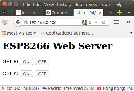 Now you can click on the On / Off button to change the GPIO levels, and with GPIO 2 it will also turn on and off the blue LED on ESP-12 module with OFF (low) = LED on and ON (high) = LED off. The URL will also change accordingly, for example GPIO 2 OFF will show the URL http://192.168.0.106/?pin=OFF2.
Finally, after some small challenges, NodeMCU is not that difficult to setup after all. Hopefully, this will help a few people getting started faster.

Jean-Luc started CNX Software in 2010 as a part-time endeavor, before quitting his job as a software engineering manager, and starting to write daily news, and reviews full time later in 2011.
Support CNX Software! Donate via cryptocurrencies, become a Patron on Patreon, or purchase goods on Amazon or Aliexpress


Does somebody know if you can get this dupont cables for connectors of 0.5mm?
I find this instructable by acrobotic very easy to follow:
http://www.cnx-software.com/2015/10/29/getting-started-with-nodemcu-board-powered-by-esp8266-wisoc/
@sk
I guess you meant to link to http://learn.acrobotic.com/tutorials/post/esp8266-getting-started
Oops! 🙂
Yes, that’s right. Though I actually saw it here:
http://www.instructables.com/id/Get-Started-with-ESP8266-Using-AT-Commands-NodeMCU/?ALLSTEPS
@Roel
Why do you want 0.5mm Dupont cables? Smallest I have seen is 2mm, most are 0.1in (2.54mm). 0.5mm is extremely small, so small I have difficulty soldering it.
I think the problem is with your code. You set the AP settings wifi.sta.config(“ROUTER_ESSID”,”WIFI_PASSWORD”) which is immediately followed by this print(wifi.sta.getip()) . This procedural attitude is not right with this board. You should hook up a function with wifi.sta.eventMonReg(wifi.STA_GOTIP, yourFunction()) before you make server socket etc. Hope this helps.
@Johny007
The print is just for debugging, so it did not introduce issues. But you may be right, that we should probably make sure we acquired an IP address, before trying to print the IP address…
Very cool, I went through much the same with my doit.am V1.0-clone board (~$10 from banggood), though now I’m just using it as a fancy UART adapter running ESP-Link from JeeLabs. One difference with the V1.0 is it uses a SiLabs cp2102 for the serial chip instead of a ch340, I don’t know if that would have any effect on your intermittent comms problems, though. I’ve been using picocom lately, and it has a very handy CTRL-A menu that lets you quickly “step” the baudrate up and down, so it’s pretty fast to cycle through various bauds to try them… Read more »
Not to poop at your party or anything, but MXChip now has a competitor to the NodeMCU in a similar form factor, using their EMW3165 module. ARM Cortex M4 & Wifi. Same price point as this board. The ARM core opens up a bunch of possibilities, since the ESP uses the far less common Xtensa core. Search for “WifiMCU”, and you’ll find it. But … this module/board is new enough on the market that the community has not implemented all the wonderful stuff that it generally does, not yet. Plans are to have the Lua interpreter, and the Espruino software,… Read more »
@Andrew
NodeMCU is around $6 on aliexpress – http://www.aliexpress.com/item/V2-4M-4FLASH-NodeMcu-Lua-WIFI-Networking-development-board-Based-ESP8266/32448662166.html
WifiMCU is around $11 – http://www.aliexpress.com/item/new-WiFiMCU-Wireless-WiFi-Development-Board-Using-Lua-From-EMW3165-diy-rc-toy-EMW-3165-remote/32443123471.html
Do you have a way to get WifiMCU cheaper ?
@Andrew
@Bruce
I wrote about EMW3165 module a little while ago, but I never noticed WiFiMCU board. They did not had a very successful crowdfunding campaign though.
The module itself is $8, so quite more expensive than the sub $3 you can get ESP8266 modules for.
Still worth an article, for the extra GPIOs, and maybe it has enough memory to supports HTTPS.
@Jon Smirl
Jon,
I’m trying to debug a router. It’s a main-board with a daughterboard. The connectors are 0.5 mm. I want to break it out to find the serial console.
Are you measuring the pitch of the header? The distance from the center of one pin to the center of the next? A 0.5mm-pitch pin header is unbelievably small. The pins themselves would have to be so thin (0.15mm, maybe?) that I don’t think you’d be able to plug them into anything without the pins just bending instead of going in. It sounds incredibly exotic and expensive and impractical (because there’s already cheaper, smaller, more common, and more robust non-pin-header connectors widely available as an alternative), and it’s really unlikely to even exist. If your measurement is the width of… Read more »
@John S.
John,
thanks for the answer, you made me a lot smarter. i did indeed measure the pin, not the pitch. The connector is more like a ide connector of a 2,5 inch harddrive but smaller. I don’t have the device with me this weekend, but monday i got it back. Probably the pitch will be 2mm.
@roel
2mm Dupont are not that common, but you can get them for cheap on Aliexpress.
http://www.aliexpress.com/item/20pcs-in-Row-Dupont-Cable-20cm-2mm-pitch-female-to-female-2P-to-2P-wire-for/32364078824.html?spm=2114.031010208.3.11.OyMnOr&ws_ab_test=searchweb201556_4_71_72_73_74_75,searchweb0_0,searchweb201560_9
@Jon Smirl, @roel:
There are also 2mm to 2.54mm dupont cables available (I got mine at ElectroDragon). That’s handy if you want to be able to connect the other end to something with 0.1″ headers, like a usb-serial device or a breadboard. You’d also need long male-to-male 0.1″ pin headers to convert the female 0.1″ connectors into male connectors for using with a breadboard.
Or I assume the 0.1″ ends are handy; I haven’t actually tried plugging a 2mm female dupont connector onto a 0.1″ square pin — would it fit?
I advise you to not use any of the outdated releases from https://github.com/nodemcu/nodemcu-firmware/releases. They’re old, unmaintained, suffer from memory issues and contain modules that you probably won’t need (but still eat memory. Use http://nodemcu-build.com/ or the Docker image at https://hub.docker.com/r/marcelstoer/nodemcu-build/ to build your own custom firmware from the NodeMCU dev branch. Disclaimer: both services are from yours truly.
for the 0.9 dev kit, span it over two of the power supply strips, for the 1.0 use a single power strip.
I’ve played a bit more with NodeMCU. The serial connection stability issue is because I’m going through a USB hub, and if I connect it to my computer directly it works OK.
I’m controlling an AC water pump with it now. Still using firmware 0.9.6, as firmware 1.4 (master) and 1.5.1 (dev) do not work. The main issue is reconnecting to WiFi is the router is turned off and on. I think it can be done with callbacks (wifi.sta.eventMonReg), but firmware 0.9.6 does not seem to support it.
Hey, thanks for this great article. If only I had found this yesterday when I got my NodeMCU, would have saved me couple of hours :D. Documentation is indeed pretty hard to find compared to Arduino stuff.
Thank you for the guide! It help!!
Can we do serial communication between NodeMCU and Arduino using usb cable?
Hello
Thanks for the tuto, but when I disconnect the pc to put it elsewhere by feeding with an external battery it does not work.
Thank you for your help
@has
I’ve had a NodeMCU running on its own to control a relay for nearly a year (Now replace with Sonoff TH).
What happens if you connect it to a USB power adapter, do you have the same problem as with a battery?
If you reconnect the board to the PC, can you still see your init.lua file?
For v0.9 boards You can take two breadboards and connect them side by side, and it works fine.
(and thanks for pinouts!!)
You are closing the connection directly after sending. This is not working for me, because the connection is closed too early. Its better to set a callback, so the connection is closed when the transfer is finished.
This is done by replacing the line
client:close();
by
conn:on(“sent”,function(conn) conn:close() end);
Maybe it depends on the firmware version.
Thanks for your helpful posting.