
A couple of months ago, I wrote about a Raspberry Pi battery kit with a 3,800 mAh battery, a battery control board, an acrylic enclosure, and an heatsink + fan set that I found on DealExtreme for about $22. I decided to buy it once I got confirmation the battery was included, and so today I’ll write about my experience assembling the kit, and running it with a Raspberry Pi 2 board. If you are only interested in the “RPi PowerPack” battery control board and battery, you can find them on Banggood for $11.93.
Raspberry Pi Club Battery Kit Unboxing
DX put all the accessories inside a zip bag, and shipped it in a bubble envelop.
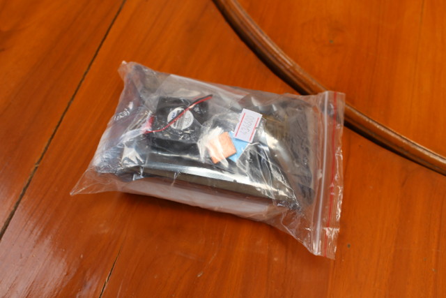
It contains a white box with the RPi PowerPack V1.0 battery and battery, several screws, spacers, and bolts sets, a fan with screws, an acrylic case with three layers, an heatsink set with two aluminum heatsink for the Broadcom processor and USB hub, and a copper plate for the memory, as well as a short USB cable to connect the power from the battery board to the Raspberry Pi.
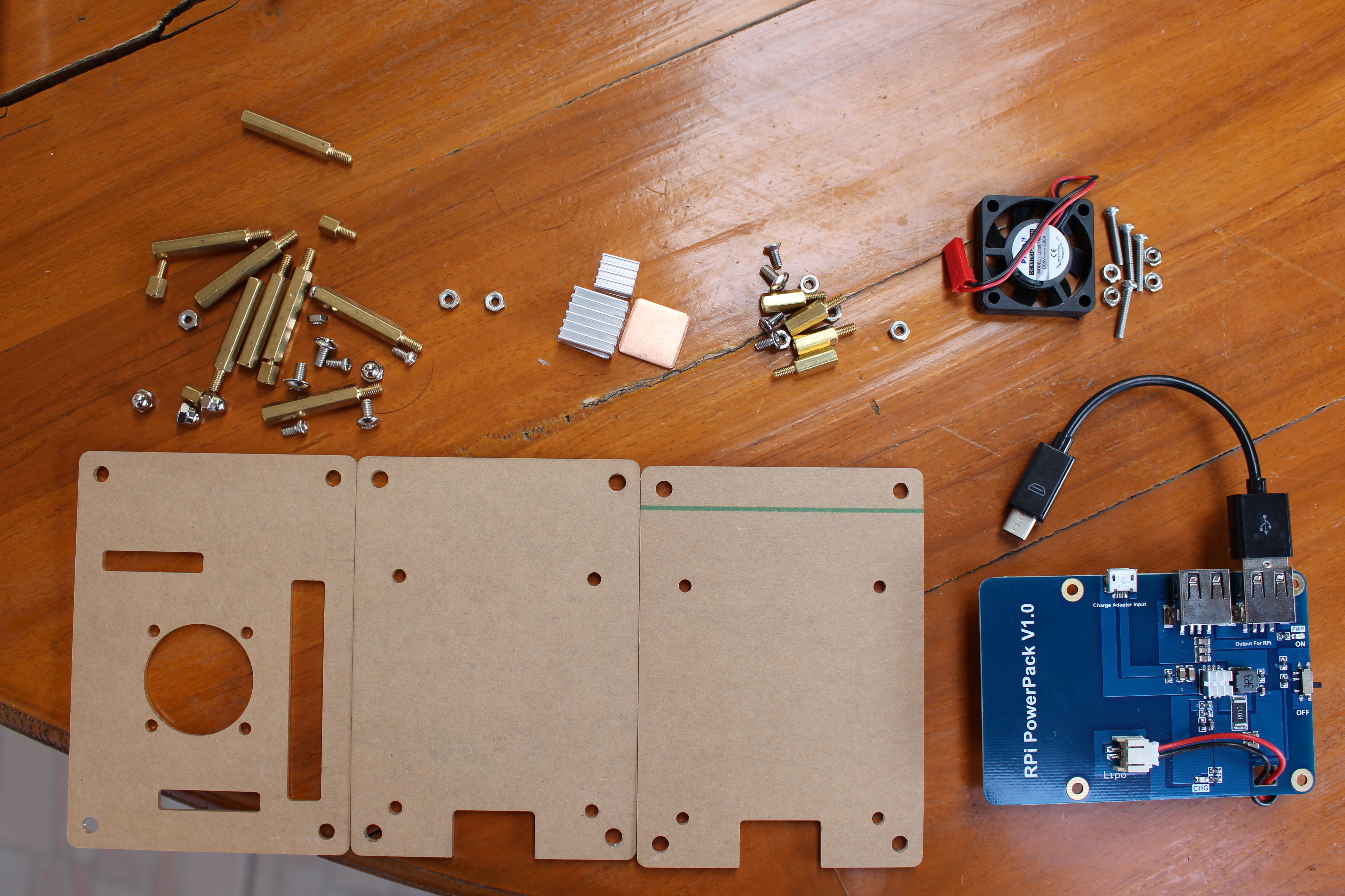
The three acrylic plate are covered by brown covers on each side. It can be peeled optionally, but I discovered they would not come off that easily, so I left it that way.
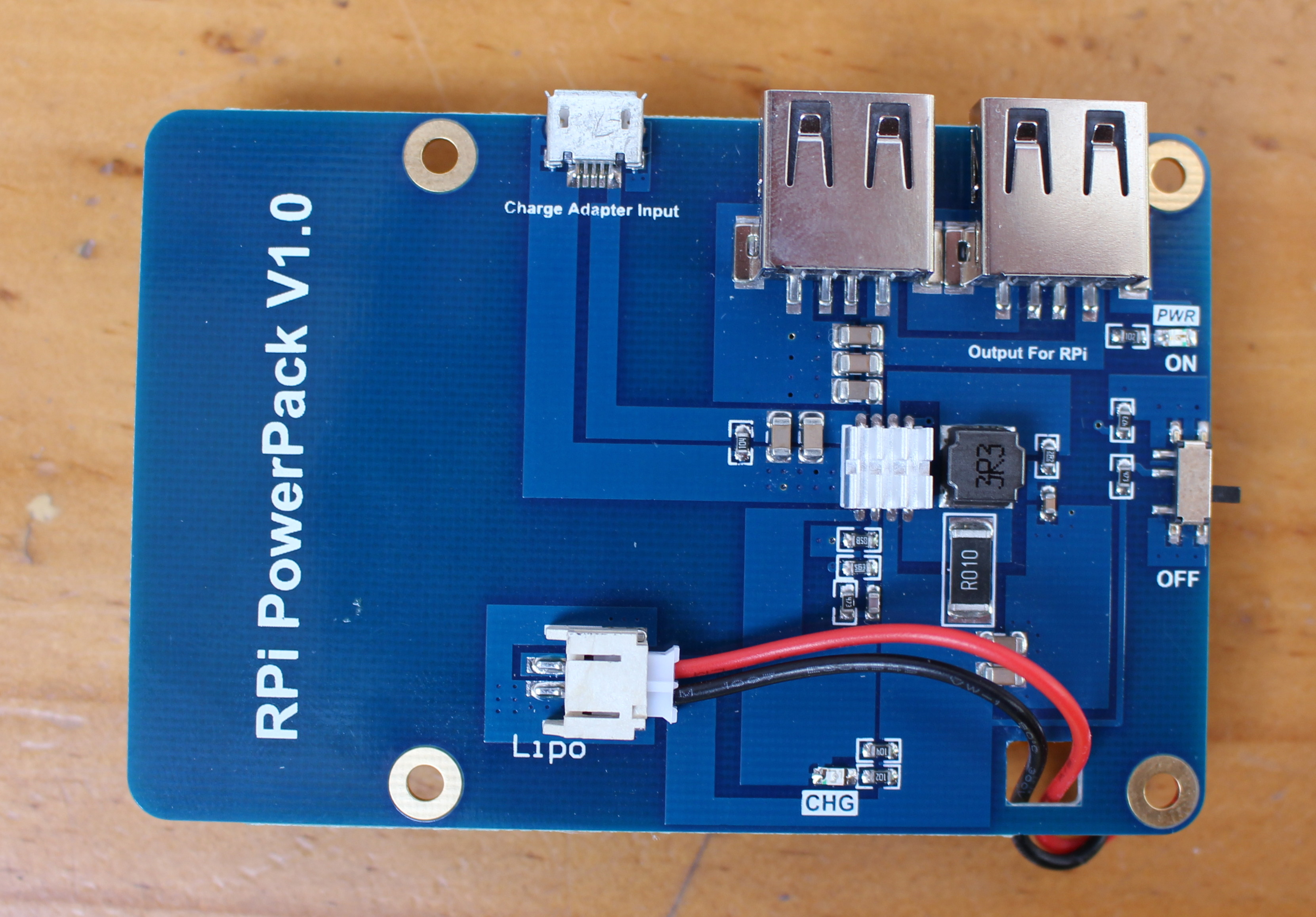
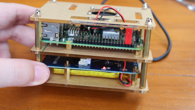
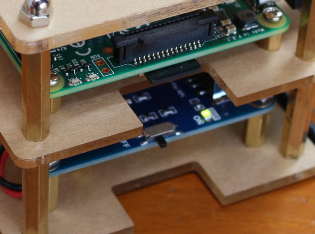
The top of the top has the connector for the battery (already connected), two USB ports include one “Output For RPi” to connect to Raspberry Pi micro USB port for power, one micro USB port to connect a 5V/2A charger, an On/Off switch, and a charge status LED.
The board can be used a as dumb UPS taking care of keeping power during outages, but you could make it more useful with some hardware hacking, by connect the Charge status LED to the Raspberry Pi board to find out when the battery is charging, as as well as the positive output from the “LiPo” connector via an ADC chip in order to monitor the battery voltage level in order to know when the battery level is critical, and to take actions such as powering off the Raspberry Pi board.
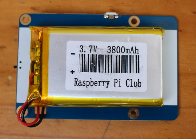
The back of the board just have the 3,800 mAh battery firmly attached to the board.
Raspberry Pi Club Battery Kit Assembly
Assembly is quite straightforward if you look the picture on DealExtreme, but I’ve shot a video explaining how to assemble the kit. Sadly, my Linux based video editor (Openshot-qt) is very unstable, and I’ve not been able to create the video after multiple attempts (any recommendations for a Linux Video Editor with fast forward support?).
But basically I did as follows:
- Fasten the Raspberry Pi board to the middle plate with the four smaller spacers and corresponding bolts.
- Insert four long spacers to the top plate (with the hole for the fan)
- Attach the fan to the top plate with its screws/bolts
- Connect the fan to 5V (pin 4), and GND (pin 6)

- Fasten RPi PowerPack to the bottom plate with four medium spacers, screws (bottom), and bolts (top)
- Screw four long spacers to the long spacers instead on the Raspberry Pi acrylic plate
- Attach the bottom cover with the four remaining screws
- Insert the short USB Cable between the USB port of the battery board and the micro USB port on Raspberry Pi board
- Done!
I could not find one screw during assembly, but finally they are all accounting for. Just one decided to hide under a bag 🙂
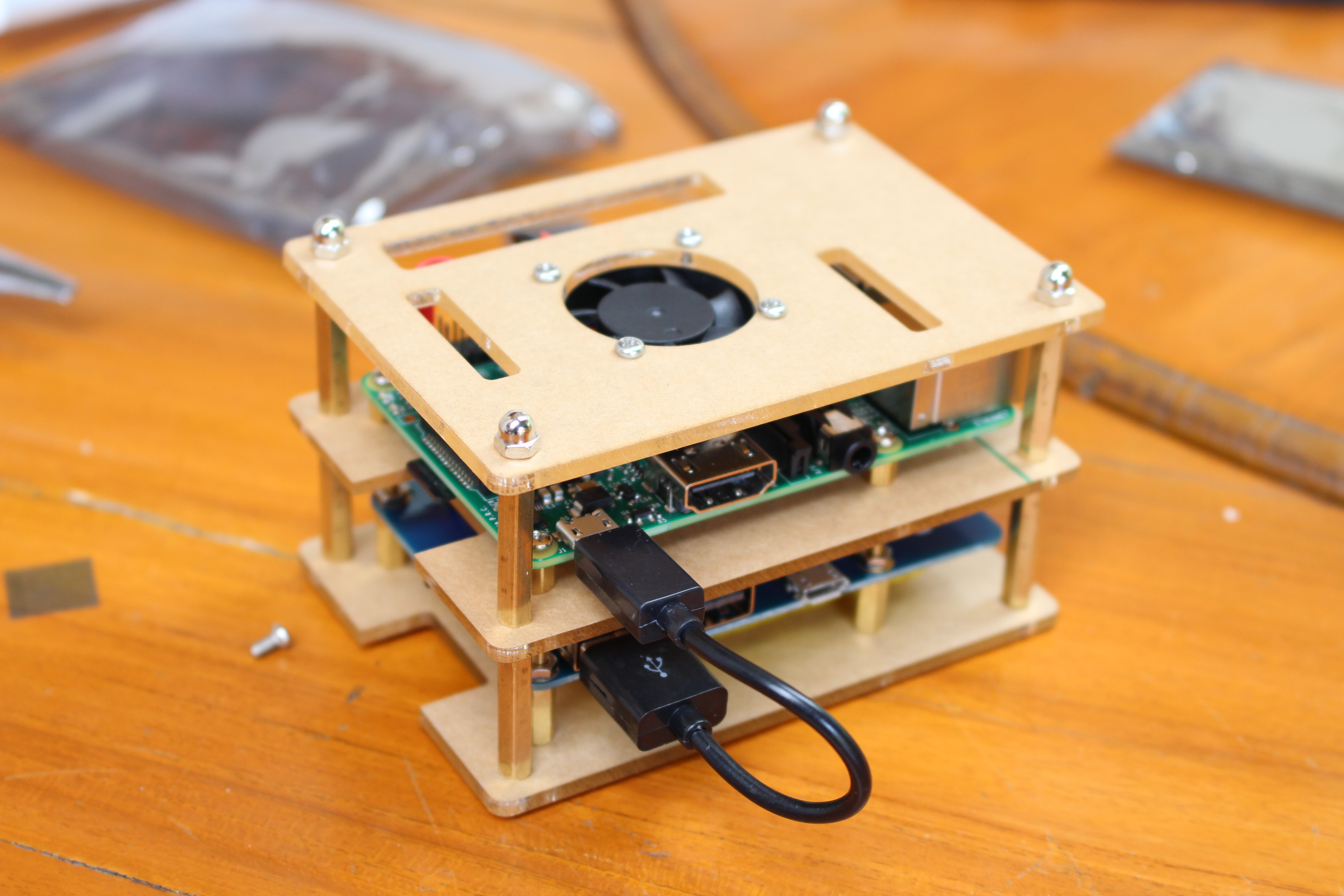
Raspberry Pi Club Battery Kit Review
Now that assembly is complete, it’s time to connect a 5V/2A micro USB power supply to test the battery and fan.
As soon as I applied power, I noticed that the fan was turning, and Raspberry Pi 2 board running, irrespective of the On/Off switch on the battery board. The charge LED is turn on as long as power is applied, and the battery is not fully charged.
 Then after I cut off the power from my power extension, and the Raspberry Pi board was still running fine, although the fan was turning a little faster, likely because the voltage straight out of the battery board is higher than the one from the power supply (e.g. 5V vs 5.4V). It’s only in this mode (no mains) that the OFF mode for the power switch is useful, and Raspberry Pi board will stay powered off.
I’ve also let the Raspberry Pi 2 run Raspbian in idle mode for over two hours on the battery and no problem. A 3.7V / 3,800 mAh battery has about 14 Wh capacity, and since the Raspberry Pi consumes less than 5 Watts in most cases, it should be good for at least 2 to 3 hours, but it depends on your load. Disconnecting the fan would also extend it a little longer.
When I tried the UPS mode in the video review above I did not connect the Raspberry Pi to a monitor, but once I did, I discovered the screen will blink (black) for about a second when switching from mains to the battery, and for one out of my 10 tries, the board rebooted while switching power from mains to battery. So this may not be a 100% reliable solution for UPS. [Update: See comments below as the fan seem to affect the results]

Jean-Luc started CNX Software in 2010 as a part-time endeavor, before quitting his job as a software engineering manager, and starting to write daily news, and reviews full time later in 2011.
Support CNX Software! Donate via cryptocurrencies, become a Patron on Patreon, or purchase goods on Amazon or Aliexpress


“once out of my 10 tries the board rebooted while switching power from mains to battery” –> this can be called an absolute fail already. 10 percentage failure rate is way too unreliable. Would be interesting how this looks like when the board is under some load. Did you do another series of test while running ‘stress -c 2’ or something like that? UPS mode with Allwinner devices that come with a PMU is way more reliable. Did some tests with an Olimex Lime2 a week ago and there by choosing crappy cables that led to severe voltage drops under… Read more »
@tkaiser
Without fan + “stress -c 4”: 5 tries = no problem.
With fan + “stress -c 4”: 3 tries = 3 reboots.
Yesterday I started with fan a few times at idle (with one failure out of 5 or so), then removed the fan (no failure).
A few more tests with USB HDD, no fan, “stress -c 2”: 6 tries, 2 reboots. Somehow, the Raspberry Pi sees the HDD as a USB device, but lsblk does not return anything. When I switched between mains and battery, I can see the system also renumerated all USB devices starting with: [ 52.484182] usb 1-1.3: USB disconnect, device number 18 1 [ 52.484182] usb 1-1.3: USB disconnect, device number 18 and while on battery this happens in loop apparently because of over current issue: [ 133.353727] usb 1-1.4: new low-speed USB device number 50 using dwc_otg [ 133.853728] usb… Read more »
The same problem occurs with my hard drive when I connect the 5V/2A power supply directly to Raspberry Pi 2 board… and I’m using the power supply that works best with all boards using micro USB port for power…
@Jean-Luc Aufranc (CNXSoft) Haha, so the usual ‘avoid any device using Micro USB for DC-IN that needs more than 10mA’ applies here also 😉 What you reported regarding increased fan speed when running on battery seems to indicate that the board’s step-up converter is fixed and leads to a overvoltage situation as long as the battery’s voltage is in the normal range? BTW: Do you have any of the A20/AXP209 boards with crappy Micro USB for DC-IN lying around? Eg. Banana Pi, Pro or LinkSprite PCDuino 3 (Nano)? If you replace the RPi with one of these boards and use… Read more »
looks like a “too simple” design to be fail safe. The usual recommendation with rpi, if your supply is not extremely stable (or oversized) : do not use the microusb power, use the gpio supply but only if your supply is properly regulated of course, as gpio input will not go through onboard 5v regulator ! @Jean-Luc Aufranc (CNXSoft) whenever you get some reboots on your rpi and assume it’s coming from the supply, put a beefy (10000uF) capacitor on one of the gpio 5v pin. You can reduce the capacitor (2200uF should be enough) when you know it’s reliable… Read more »
@Jean-Luc Aufranc (CNXSoft)
i forgot, did you get a chance to check which power chip they used on that power board ?
thx
@mdel
You can buy the acrylic enclosure only for $8 on the DealExtreme link by selecting “Transparent” option.
I’ve removed the heatsibk from the power chip, but I can’t see any marking. It’s an 8-pin SMT component.
No serial connector to shutdown rpi when lipo is low! too simple and useless lipo controller.
A board with two way off switch power, sw on/off and 2 input for poweron and poweroff.
There is only need an small ucontroler to have a good handling lipo battery,,,I don’t understand why none cpu board have an cheap and separate ucontroller like arduino, amtel or microchip to make this cleanly and easy
@boobwrt There’s no need for any separate µcontroller if you choose a device where the SoC is accompanied by a PMIC with appropriate driver support. You can choose any Allwinner A10/A13/R8/A20 board with exposed battery connector and you’re already done since AXP209 PMIC IC deals with the battery, you can initiate a shutdown when you want, monitor charging/discharging and so on. Since UPS useage sounds like ‘server’ I highly recommend looking at Olimex’ Lime/Lime2 boards since there the power scheme also powers a connected SATA disk when running on battery and the PMIC also compensates voltage drops on DC-IN by… Read more »
@boobwrt
A real world example using a Lime2 with large battery as UPS for the Lime2 itself, a large SATA disk and also another device powered through the Lime2’s USB port: http://forum.armbian.com/index.php/topic/1631-tutorial-marriage-between-a20-and-h3-ups-mode-sunxi-pio-utility/?p=12714
okay thx, too bad.
i tried to find a “2 amps” lithium battery “powerbank” chip a few weeks ago to upgrade my old UPS board and ended up opening my recent battery packs to look at their chips references, but that only sent me on a wild goose chase, browsing chinese websites or alibaba catalogs..
I will eventually end up using a powerbank board, i did find a few around $5 or i could use that one.
Please tell me what is the plug for the battery ?
I have a board without battery and I can’t find a plug to put on my battery.
Thanks
@Cristian Istrate
As you can see from the pictures above, the battery is connected to the “LiPo” connector.
I have the 2.0 version. But pulling out the power with fully charged battery i have always a reboot. 🙁
What should be the voltage of the battery when is fully loaded?