
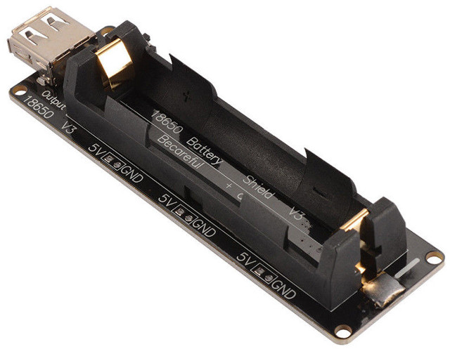
If you’re looking for battery power for one of your projects, you may consider a “18650 battery shield” – going for just above $2 on Aliexpress or eBay – for powering Arduino boards, Espressif ESP8266 or ESP32 boards, or any board that can be powered by 5V up to 2A via USB or headers, or by 3V up to 1A via headers.
 Specifications listed on eBay/Aliexpress:
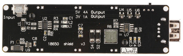
- Power Input – 5 to 8V via micro USB port up to 0.5A charging
- Power Output
- 5V via Type A USB port
- 3V up to 1A via 3x 2-pin header
- 5V up to 2A via 3x 2-pin headers
- Misc – 1 switch control USB output, LED for charging status (green = full, red = charging)
- Battery protection (Over-charge or Over-discharge)
- Dimensions – 9.8 x 2.9 cm
You’ll need to add your own 18650 battery, and be careful about polarity while installing it, since putting it in the wrong direction would destroy the charging chip. Some sellers also stuff “Raspberry Pi” keyword in the product title, and they often do this for search engine optimization (SEO), but at least some people have shown it to work with a Raspberry Pi board too. It’s unclear whether it can act as a basic UPS (Uninterruptible Power Supply) without status. Has anybody tried?
Thanks to Harley for the tip.

Jean-Luc started CNX Software in 2010 as a part-time endeavor, before quitting his job as a software engineering manager, and starting to write daily news, and reviews full time later in 2011.
Support CNX Software! Donate via cryptocurrencies, become a Patron on Patreon, or purchase goods on Amazon or Aliexpress. We also use affiliate links in articles to earn commissions if you make a purchase after clicking on those links.


re: UPS use, it looks like this board is a TP4056 and a boost converter, both directly connected to a battery, so it would work, kind of, for a low-power load. If that is the case, I’d recommend against it for two reasons: first, the TP4056 has a 1.2A absolute maximum battery output current at battery voltage, which would be shared between the battery and the loads, so don’t expect to draw 1A through the shield continuously, let alone 4A. Second, the heat put off by a linear charger such as the TP4056 is significant and, being placed directly under the battery, would surely reduce battery life and possibly damage it by charging when hot.
Also, it’s pretty silly using a battery to feed a device using linear voltage regulators, a design choice all too common on the famous boards.
If you need a power-path controller, better to get a power-path controller. TI’s bq24195 is efficient, highly integrated, relatively easy to design-in, provides status and control via I2C, runs cool, and isn’t too expensive.
Wow that’s pretty cool! I have built countless battery-to-5V adapters using a wide range of DC-DC converters myself. Some of them are unable to power an Attiny85 which doesn’t consume enough to keep them running. Others fried some devices because they don’t react fast enough to current variations. Others are not able to power an ARM SBC. And others fry from time to time. Each time I have to pick the iron to fix something.
This one looks very very interesting, especially for the form factor and the fact that it provides a 3V output, instead of seeing 5V turned into 3V+losses via an LDO on board. I do have some doubts about the claimed 4A output under 5V (written on the board) since most DC-DC chips have a 4A max MOSFET, thus it’s more likely 4A under 4.2V but let’s try and see. Given that the 3V output is announced at 1A, it’s possible that they included an LDO connected to the 5V output.
I’m ordering one to test it. What would be nice for small boards would be a similar one, smaller, using 14500 batteries. These ones are small and cheap and often more than enough to power any small board.
So this is about the same as a powerbank you buy at the MediaMarkt, without the 18650 battery, and with a 3V output?
Not quite there for UPS functionality, more for portable on-the-go RPI use.
Brown-outs cause a RPI reboot due to slow switch between USB -> 18650. (Can be fixed by supercaps/ultracaps on available 3.3V and 5V respectively)
USB power restoral works as expected (no power interruptions).”
I too would like to see a smaller one for 14500 batteries.
This specific “18650 Battery Shield” is obviously designed only for low-powered microprocessor based development boards such as Arduino and ESP8266/ESP32. It is not meant for development boards which require more power, like Raspberry Pi, ODROID, and similar derivatives like Banana Pi, Orange Pi, etc..
Ordered 3. Should be good for some projects, will see how much magic smoke I let out
Oh great ! I’ve ordered a couple to test them.
I’ve changed the battery on my Thinkpad which didn’t charge anymore. Out of 6 cells, 5 of them are perfectly working and only one was dead.
So I’ve got some 18650 batteries to recycle on ESP projects (a couple of them are already converted into power bank) but here I like the 3V output 😉
@Tof
Is it 3V or 3.3V output?
@zoobab
I’ve not tested it yet personally, as I made the order yesterday on Ali.
But I think it won’t be 3.3V. Do expect 3V – 3.1V, not more.
Here is a reading on multimeter at 3.15V on the V2 module:
https://cdn.tindiemedia.com/images/resize/-4XlpcSIbjirjm6V_0g0TOQpogw=/p/full-fit-in/2400×1600/i/87204/products/2016-08-07T09%3A26%3A10.483Z-SAM_1942.JPG
In my opinion v3 module does not differ in output voltages, but rather in battery protection functions.
This shield while not powerful enough for standard Pi boards, should suffice for Pi Zero W 🙂
That could be a cheap solution for “always-on” (I mean : can survive short term power outages), or portable PI Zero projects.
So I’ll test piCorePlayer (on Pi Zero W) + PAM8403 5V amp on batteries, embedded in a portable speaker. I miss a portable squeezebox client for my multiroom audio solution to be complete.
So I received mine. They’re not bad, but nothing impressive at all either. I can respond to some of the questions asked above :
– the 3V output is indeed 3.0V
– the 5V output is 5.0V, but the chip employed (FP6298) uses resistors to match a 0.6V reference and supports up to 12V output, so those wishing to modify it to output 5.2V to improve stability of micro-USB powered boards could easily do it by adding one resistor on top of an existing one.
– the so-called 2A output (or 4A as written on the board) is overrated. I managed to get around 1.6A out of it to power my bike’s light, but simply adding a USB power meter in the middle was enough to make it cut-off, indicating I was extremely close to the limit (I just happen to know that this light drains 1.6A from 5.0V based on measurements using regular 5V batteries). I haven’t checked how this cut-off is implemented, I suspect they’ve put a MOSFET in series with the DC-DC chip, I’ll have to check, maybe with a solder drop it can be disabled.
– the power switch only cuts USB, there’s no way to disable 3/5V output when not used.
– when it cuts off, the only way to reset it is to remove and reinsert the battery, which is very inconvenient
– the charging circuit is indeed a TP4056.
As a conclusion I’d say that the only benefit I’m seeing here for hacking compared to a regular power bank is the availability of a 3V output. The fact that it’s not insulated and you cannot power it off means you can’t let it lie on your desk in the middle of other stuff, at the risk of causing a short-circuit, so for most use cases I tend to find it less convenient than a regular USB power bank. It could be nice for hacking on ESP8266 that want 3V though.