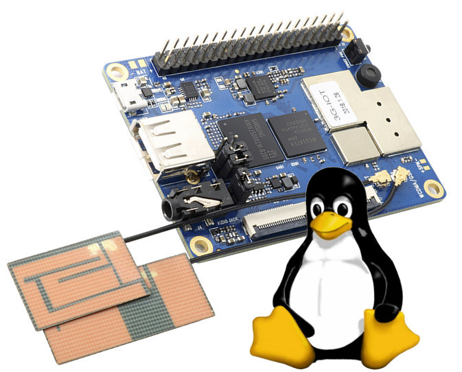
Shenzhen Xunlong has launched several cellular IoT boards over the last few years with Orange Pi 2G-IoT, Orange Pi 3G-IoT and Orange Pi 4G-IoT, but each time, they are launched with Android support only. Linux support on the 2G board has never been great, while the Android 8.1 SDK for Orange Pi 4G-IoT was released earlier this year, but no Linux image are available.
This leaves us with Orange Pi 3G-IoT board that just got its first Linux based firmware images released today on both Baidu and Google Drive cloud storage storage services.
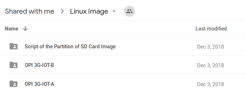
 Four images are available for Orange Pi 3G-IoT-A (256MB DDR2) and Orange Pi 3G-IoT-B (512MB DDR2) boards with images booting from eMMC flash or micro SD card. A shell script (tar_image.sh) is provided to flash the image to the micro SD card since the latter for follow a specific partition layout.
 Sadly, there’s no mention of the distribution used, or whether the company used buildroot or the Yocto Project to create the images.

Jean-Luc started CNX Software in 2010 as a part-time endeavor, before quitting his job as a software engineering manager, and starting to write daily news, and reviews full time later in 2011.
Support CNX Software! Donate via cryptocurrencies, become a Patron on Patreon, or purchase goods on Amazon or Aliexpress


> A shell script (tar_image.sh) is provided to flash the image to the micro SD card
This script looks more like a hack to assemble a skeleton containing bootloader+kernel with some random userland to generate the images that can be downloaded now:
The last time I booted such a Xunlong ‘Linux’ image (IIRC with Allwinner H5) it was exactly like that. Userland recycled from other images (the bash history and contents of some directories contained also some stuff for their Orange Pi 2G-IoT board) and all the important stuff missing.
I downloaded the tar.gz file and looked at the premade image It doesn’t even HAVE /lib/modules.
I’m not that surprised 😉
It’s obvisously just an Android image with replaced userland. But it seems everything ‘works great’: http://www.orangepi.org/orangepibbsen/forum.php?mod=viewthread&tid=3888&extra=page%3D1
Come on! Who needs keyboard in 2019, that’s so last century 🙂
It’s a great reminder of one of my favorites last century: NO keyboard detected. Press F1 to resume 🙂
BTW: the history behind this stupid looking message is even more fun: https://alphahole.net/?p=1011
> https://alphahole.net/?p=1011
I’ve never read such a ridiculous and wrong explanation. Everything is not only wrong but completely made up there! The guy obviously has no idea what he’s talking about, there’s no memory scanning, even less intervention from an external processor to redirect anything. They just needed to disable the A20 line to maintain compatibility so that code using segments higher than F000 and expecting to access the beginning of the RAM (e.g:. interrupt vectors) in the same segment continued to work as designed. And by then there was no GPIO to do this. Given that the 8042 microcontroller used for the keyboard had numerous available I/Os, some of them even used to enable/disable the speaker, it was obvious to add another one to control this pin. Many later PC compatibles extended this and added other GPIOs there. I’ve seen some mapping the turbo control on it so that the frequency could be adjusted by software.
The “Press F1” to continue was emitted for any hardware error detected in the BIOS. The keyboard was tested just like a number of other devices, and caused the same message to happen. It was the same type of error processing that made DOS emit “Abort, Retry, Ignore” for each and every syscall even when facing horrible I/O errors. By then it was the normal way to do this.
Orange Pi 4G-IoT Linux images have been released too: http://www.orangepi.org/downloadresources/orangepi4G-IOT/2018-12-04/b102afd89243eb51d50588ca8437b625.html
If you have any progress installing Linux onto the Orange Pi 3G IOT B, can you put your experience to http://www.orangepi.org/orangepibbsen/forum.php?mod=viewthread&tid=4206&fromuid=1658067 please?
We need your skills