
The Raspberry Pi Foundation introduced the Linux-capable Raspberry Pi board in 2012 to teach programming and computers. Since then, the company has introduced models with faster processors, more memory, faster interfaces, culminating with the launch of Raspberry Pi 4 in 2019.
The board also comes with a 40-pin header to teach electronics, but relying on a Linux SBC to blink a LED, gather data from sensors, or controlling servos is a bit over the top. So the Raspberry Pi Foundation decided to create their own MCU board called Raspberry Pi Pico powered by RP2040 dual-core Cortex-M0+ microcontroller designed in-house by the foundation.
Raspberry Pi RP2040 microcontroller
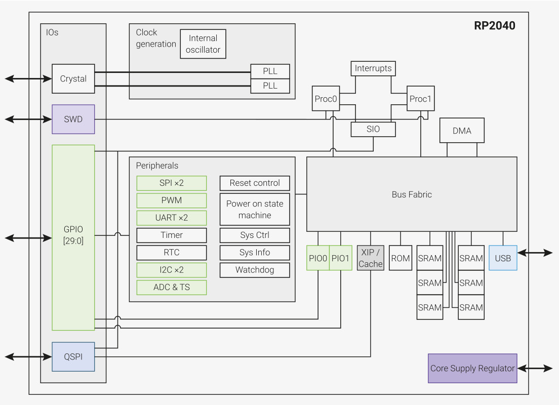
Before we look at the board, let’s check out RP2040 specifications highlights:
- Core – Dual Cortex M0+ cores up to 133 MHz (48MHz default)
- Memory – 264 kB of embedded SRAM in 6 banks
- Peripherals
- 30 multifunction GPIO
- 6 dedicated IO for SPI Flash (supporting XIP)
- Dedicated hardware for commonly used peripherals
- Programmable IO for extended peripheral support
- 4 channel ADC with an internal temperature sensor, 0.5 MSa/s, 12-bit conversion
- USB 1.1 Host/Device
- Debugging – SWD Debug interface
- Package – QFN56 7x7mm
If you wonder why RP2040 is called that way, RP stands for “Raspberry Pi”, “2” is the number of cores, “0” refers to the MCU core used (e.g. Cortex-M0+), and the last two number “4” and “0” use floor(log2(x/16k)) formula to calculate a number representing the SRAM and non-volatible storage capacity inside the chip.
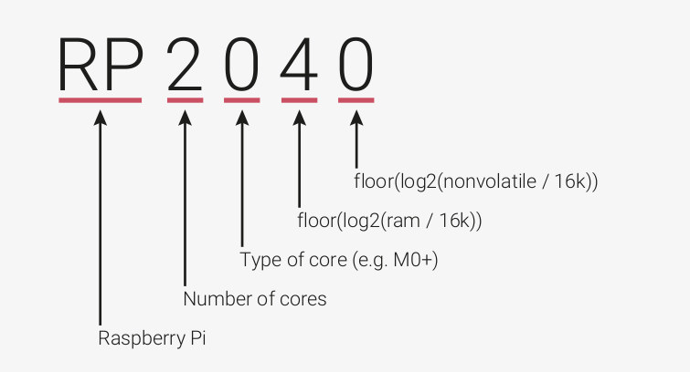
So for example, if the Raspberry Pi Foundation decided to create a single-core Cortex-M4 microcontroller with 264KB SRAM and 256KB storage, it could be named RP1444. Not sure how a dual-core Cortex-M4/M0+ MCU would be called though.
But why create a custom MCU? I’m pretty sure they could have found an existing microcontroller that does the job. But in my humble opinion, they did so to avoid having people copy the hardware too easily and use their software. They’ve probably seen what happens with the Arduino clones, and the Raspberry Pi Foundation has made it clear they do NOT allow other Broadcom BCMxxxx boards to run Raspberry Pi software in the past. As we’ve seen with STM32 fakes and clones, it’s still possible to copy the chip, but it’s much more difficult than just making another PCB.
Another reason is that they can now sell RP2040 microcontroller to makers creating their own projects/products, and this will happen as they provide a document called “Hardware design with the RP2040” to help people design their own boards and products around the microcontroller. [Update: Adafruit, Arduino, Sparkfun, and Pimoroni have already announced RP2040 boards]
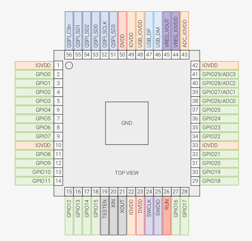
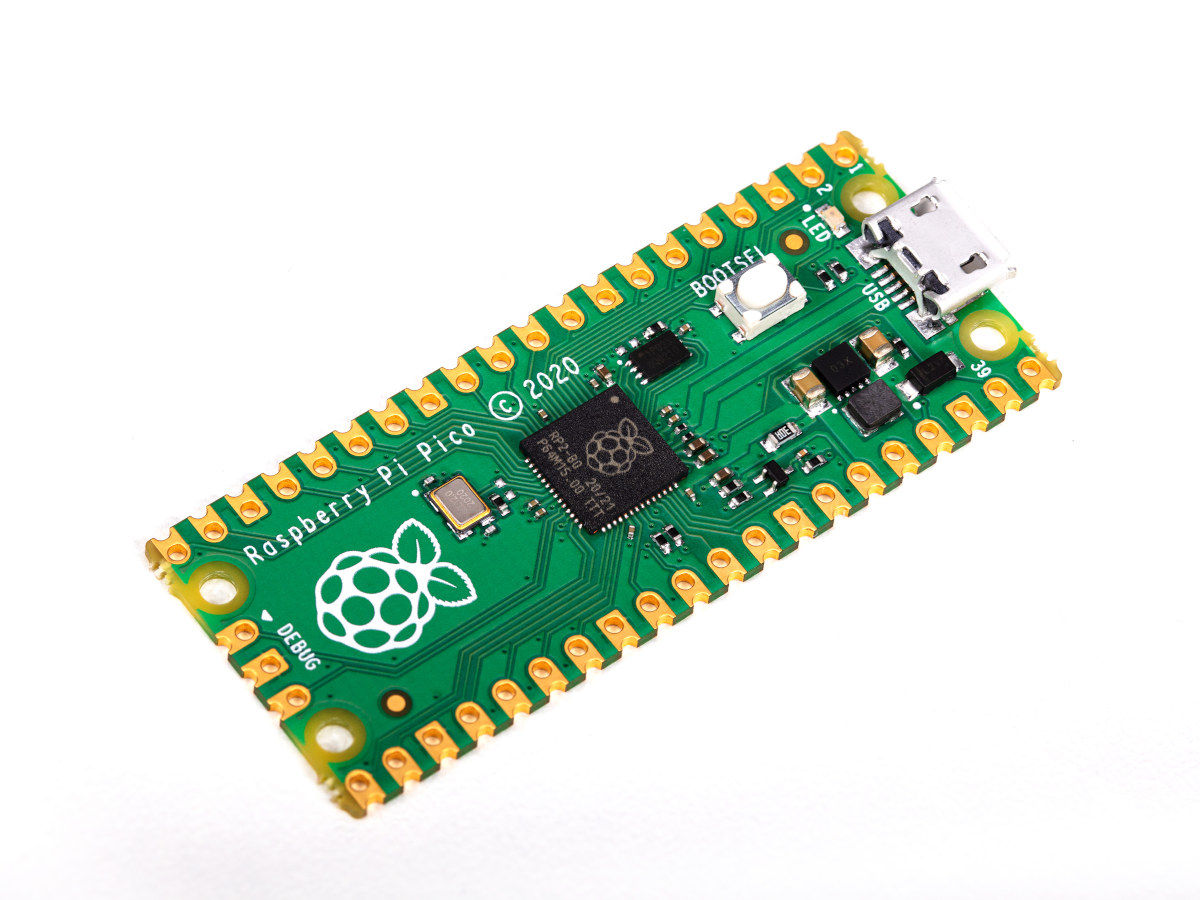
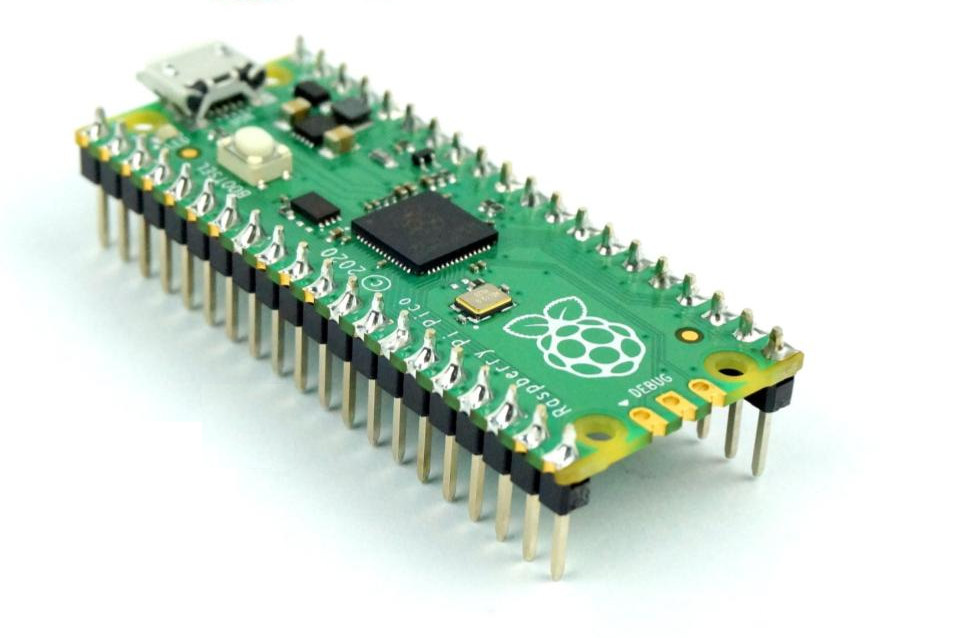
Raspberry Pi Pico
Let’s get to the board itself, with Raspberry Pi Pico specifications:
- MCU – Raspberry Pi RP2040 dual-core Cortex-M0+ microcontroller @ 48 MHz (overclockable to 133 MHz) with 264KB SRAM
- Storage – 2MB QSPI flash
- USB – 1x Micro USB 1.1 port used for power and programming
- Expansion
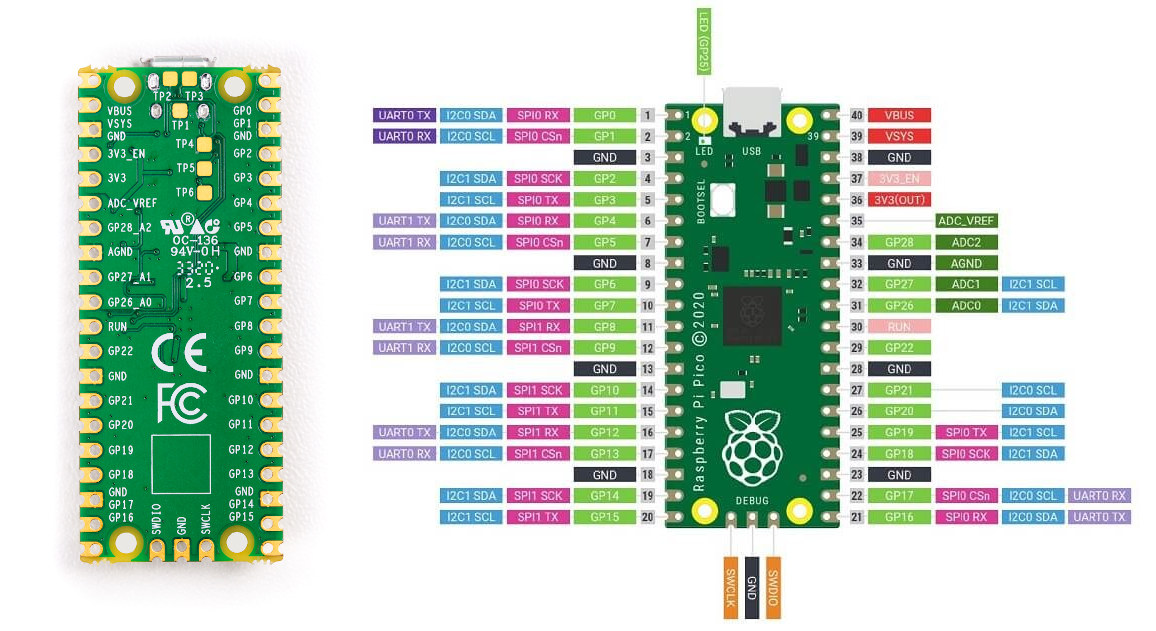
- 2x 20-pin 2.54mm pitch header and castellated holes with 26 GPIOs, 3x 12-bit ADC up to 500 Kbps, 2x UART, 2x I2C, 2x SPI, 16x PWM, 2x programmable high-speed I/O (for SD card, VGA, etc…)
- 3.3V I/O voltage
- Sensor – 12-bit temperature sensor
- Debugging – 3-pin Arm Serial Wire Debug (SWD) port
- Misc – BOOTSEL button, user LED (GP25), 1x Timer with 4x alarms, RTC
- Power Supply – 5V via Micro USB port or 2 to 5V DC via VSYS pin
- Dimensions – 51 x 21mm
It appears Raspberry Pi Pico has been designed for not only the education and hobbyist markets but also for commercial products with castellated holes allowing integration into products. The board ships without headers by default, so you’d either have to solder those yourself if needed, for example, to insert the board into a breadboard, or purchase the version with soldered headers.
 Raspberry Pi Pico offers 26 GPIO, or more I/Os than Arduino UNO, Arduino NANO, or even Arduino MKR Zero. One downside is that the pins support 3.3V only, and there’s no 5V support/tolerance as in most Arduino boards.
Raspberry Pi Pico Software and Documentation
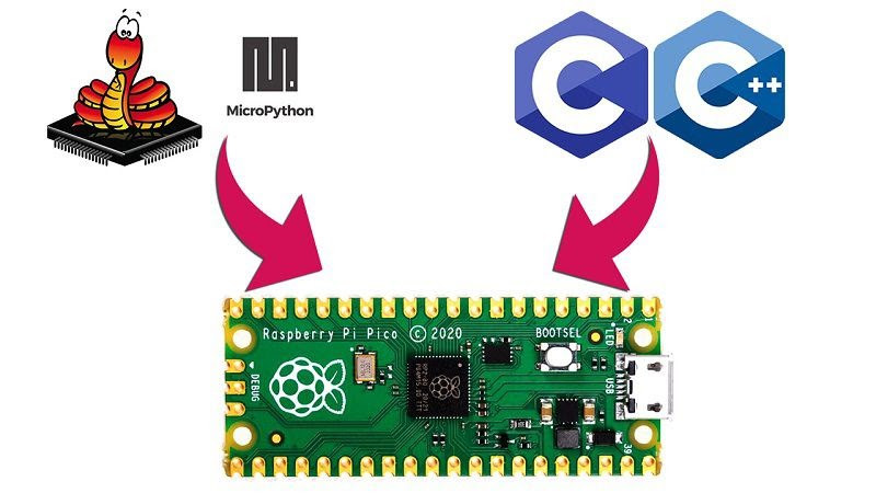
It should not come as a surprise that Raspberry Pi Pico does not support Arduino, and instead, the foundation provides supports for MicroPython and C/C++ programming with the command line or Visual Studio Code. The Python code and compiled C/C++ binary can be easily copied to the board since it shows as a USB mass storage device on the host computer, which can be any computer with a USB port running Windows, macOS, or Linux including the Raspberry Pi 4 Model B or Raspberry Pi 400 keyboard computer.
You’ll find both the MicroPython and C/C++ SDK on Raspberry Pi’s Github account, and detailed hardware and software documentation that will explain how to get started with your chosen SDK or hardware design.
 The Raspberry Pi Foundation is still committed to its educational mission and provides books geared towards younger makers such as the “Get Started with MicroPython on Raspberry Pi Pico” official guide for the new MCU board.
Pricing and availability
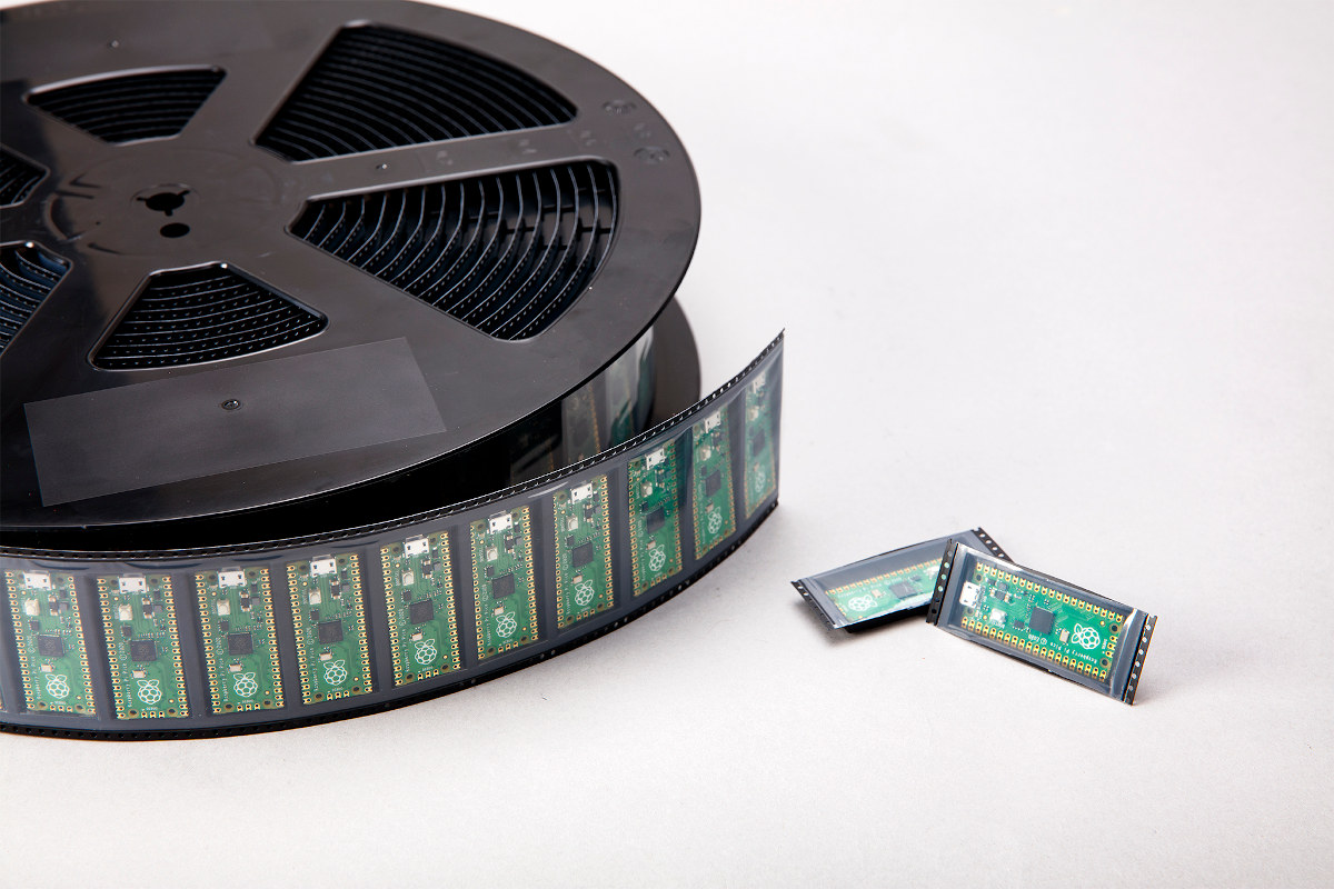
Raspberry Pi Pico official price is $4 excluding taxes and shipping. You can also purchase Raspberry Pi Pico with pre-soldered headers, and a Raspberry Pi Pico Basic Kit without or with a Pico board. The basic kit includes a breaboard, jumper cables, and some components like LEDs. You’ll find all those on the usual resellers including RS Components, Cytron (ASEAN only), and Seeed Studio. Eventually, it may be possible to purchase reels with Pico boards, but it’s not possible right now unless you are a reseller, and since stocks are limited, vendors may also limit the number of boards they sell per order.
The MCU board market is pretty crowded with the official Arduino boards (which now even look more overpriced), Arduino clones, STM32 boards like the sub-$2 BluePill, and obviously ESP8266 and ESP32 modules and boards that also include wireless connectivity for about the same price, or even a bit lower once taxes and shipping are included. All those competitors already have good software support for Arduino and/or MicroPython, C/C++ SDKs, etc… so it remains to be seen whether Raspberry Pi Pico will also be successful, but years have taught me to never underestimate the Raspberry Pi “marketing machine”!
I should receive my Raspberry Pi Pico board later today from Cytron, and a review / walk-through guide should hopefully be up this weekend or earlier next week.

Jean-Luc started CNX Software in 2010 as a part-time endeavor, before quitting his job as a software engineering manager, and starting to write daily news, and reviews full time later in 2011.
Support CNX Software! Donate via cryptocurrencies, become a Patron on Patreon, or purchase goods on Amazon or Aliexpress. We also use affiliate links in articles to earn commissions if you make a purchase after clicking on those links.


Native USB and XIP are nice features.
Might be a bit limited in terms of I/O for more complex projects.
Ahhh there was missing for the mcu family something slow and expensive like the raspberry that everybody will find extraordinary ? (small troll inside… but not totally a troll ?). The prices announced by raspberry are more the seller’s price that the final price (but everybody relays the price that they give for the press).
If there was wifi with low power consumption it could be interesting… otherwise the place is already occupied…
“wifi with low power consumption” Yeah and I want a car that gets 1,000 miles per gallon.
Buy a Tesla.
No WiFi? NO PARTY!!!! :(. :-/
Expressif will eat It.
The Arduino Nano RP2040 Connect adds a u-blox NINA WiFi and Bluetooth module.
It would be nice for it to be integrated in the chip, but both WiFi and Bluetooth are evolving standards, so using an external interface and using one of the cores to manage it makes a lot of sense.
Qfn not really hobby friendly, so another way to push ready made modules…
QFN is hobby friendly. Much more friendly than high pin count QFPs.
How?
Sorry but I can’t imagine how to solder it, especially the burried ground pad.
Tqfp and similar never posed a problem to me, so it’s definitely new to me and would appreciate some pointer to hobby style qfn soldering methods
>How?
If you have hot air and solder paste just lather paste on the footprint, dump the component down, warm it up until it’s all melted, poke the component a bit until it clicks into place and then press it down a bit to push out excess solder.
If you have bridges around the chip after that cut some solderwick into a knife like edge and then run that edge around the chip with a bit of hot air at the same time to clean it up.
If you don’t have hot air you need to use footprints with extended pads so you can use an iron. You basically tin the pads, dump the component on and then use a ton of flux and keep reflowing the pads until everything is level.
For the exposed pads you need to have a footprint with big via or a set of vias so you can feed solder in the back… Just like you do with QFPs with an exposed pad.
Unlike a QFP you can drop a QFN on the floor multiple times without making it useless, you can reuse them multiple times without reworking all of the pins.
Hmmmm, thanks, still sounds more complicated to me, but ok seems it’s working with just some additional tools/design tweaks, I already feared the toaster oven 😉
Tbh at the moment I still prefer tqfp/soic etc. but at least good to know they don’t need avoiding like the plague.
Unfortunately I’m no more into this industry professionally, so no more at the source of the latest tricks 🙂
>I already feared the toaster oven
Hot plate with the temp control disabled works too. I remember someone selling a special hot plate device on tindie just for this sort of stuff if you don’t like the fire hazard.
Another tip is to use the low temp solder pastes. The melting point is so low that you will have a lot of time to get the QFN positioned etc without risking burning your board.
>but at least good to know they don’t need avoiding like the plague.
When you order a 100+ pin component from a dodgy taobao seller that decides to dump it into envelope without any protection you’ll be glad it’s a QFN. 🙂
Hey Daniel, I wanted to send you a link to this heating plate I received a week ago: https://www.ebay.com/itm/300W-260-Degree-LED-Lamp-Remover-BGA-Demolition-Chip-Welding-Soldering-Station-F/174409653519
It’s designed to desolder LEDs but works pretty well with other PCBs. I could try it with the breadbee and it eases placement and removal of components. I find it 10 times better than the over because you see small components move and can adjust them:
And I confirm that while QFN is much more frightening, with the right tools (very affordable) it’s easier than TSOP. Just have to put too much solder and remove the excess. However, visual controls are much more difficult. I think I’ve desoldered and resoldered this 80-pin SoC about 20 times during my debugging sessions, all boards included. And once I received my last CPU I immediately wanted to solder it before going to bed, it took me 5 minutes to remove the old one and install the new one (and see it boot). TSOP would have required a lot of cleaning and checking for bridges.
Just to find out it got an ESD shot…
Times definitely must have changed since I last bought such parts vanilla ☺️
This seems like a pretty weird side step to be honest.
There isn’t all that much going for this chip aside from the Pi branding.
> There isn’t all that much going for this chip aside from the Pi branding.
Actually I think it’s its only value, but this could have a positive effect on users. Indeed, while Arduino is for a lot of people, Raspberry has <b>fanboys</b>. You find RPis at totally improbable places, where an MCU would have been more suited, even just an ATTINY85. By leveraging their marketing power and making their fanboys experiment with MCUs, there’s a hope to open their eyes and drive more people to this world full of possibilities that some refused to see in the past. It could even be beneficial to Arduino and all others over the long term. If at least we could stop using high-power boards to deliver two drops of water every day to a plant for the pretext of saving water by burning charcoal, that would constitute a nice progress. I’d love to see product makers think “if I need TCP/IP I need Linux, if I need to control a motor I need an MCU, and both are not exclusive”.
> but this could have a positive effect on users.
I think what might happen is a lot of people buy these based on the brand and end up with something they don’t use after realising a microcontroller isn’t the same as bit banging something Python on the other Pis.
>“if I need TCP/IP I need Linux, if I need to control a motor
>I need an MCU, and both are not exclusive”.
I agree. But wouldn’t it be really cool if we got to the point that mainline linux could do motor control like an MCU can? 🙂 Or at least where the interaction between linux and an MCU in the same chip is so transparent that it’s almost possible to forget the MCU is there.
(apparently your opinion on who buys this brand starts to attract haters :-))
It’s not as much the OS as it is the whole. The OS is a tiny piece. Running on a multi-gigahertz CPU with 3 layers of caches and TLBs make cycles inaccurate and instruction-based short delays impossible for bit-banging. The reaction time is much higher, due to the complex task structs that are needed to store page tables, states, floating point registers and namespace info that increase context-switch and interrupt processing time. When you see that it’s possible to make a high frequency oscillator on an AVR by programming a watchdog to trigger an RST, you figure you’ll never see a linux-capable CPU boot in 1 microsecond.
Add to this the power consumption, even when suspended, a linux-capable CPU draws significantly more than the 100nA of an AVR.
Then there’s the application. When I was a kid, a hello_world program was exactly 9 bytes + the message to print. Nowadays a hello_world is multi-megabytes of crap that has to be executed. Even when a syscall notifies you of an urgent external event, you have to pile up signals on a stack (or wake up in your polling loop) and pass through myriads of abstraction layers before you can react and the program’s reaction is transformed into a pin state change.
So you can indeed imagine having access to a local MCU through shared memory and easy communication (i.e. virtual serial port and access to the MCU’s reset line) that will allow you to run native low-latency applications there, but you’ll still need to learn how to bit-bang I/O and do low-level stuff there.
Note that I’d personally love to combine both, as I definitely sit in the middle of these two worlds: I love playing with low-level bits but don’t always have enough time to reinvent the basic stuff. But I do have some hopes in the treasure hidden inside the MSC313E 🙂
>So you can indeed imagine having access to a local
>MCU through shared memory and easy communication
>(i.e. virtual serial port and access to the MCU’s reset line)
This seems to be what remoteproc is aiming for.
>But I do have some hopes in the treasure hidden inside the MSC313E
I worked out a lot of the embedded 8051 a few weeks ago. I can boot it, load code into it etc via remote proc. It seems to have a 120MHz clock that can be routed to it but I’m not sure if that means it can actually run that fast.
From some slides I saw they might have replaced it with a RISC V core in the newer parts. If that is the case I think those will be pretty interesting.
> It seems to have a 120MHz clock
That wouldn’t be that much surprising considering that the original one had a 6-clock execution cycle IIRC, so running one etched much smaller than its grandfather allowing it to deliver the equivalent of a 20 MHz traditional MCU sounds reasonable.
Do you know how many T the core is? As Willy points out, the original 8051 had a 12T core (it took 12 oscillator cycles for the simplest instructions to run). The fastest cores now are just 1T.
Yes I had that memory of a ratio of 12 due to a first divider by two to produce a 50% clock cycle ratio (input being a crystal, not necessarily symmetric), then 6 “real” cycles for instructions. It could be argued that the external frequency was already a bit of cheating, because when you run your MCU off an 11.0592 MHz xtal and it runs at 5.5 real, giving 921k inst/s, you’re seeing numbers drop quickly 🙂 But that was in the 80s and if the chip was bad it wouldn’t have been that huge a success. I’ve seen some Dallas chips run at 1T and higher frequencies (20 or 33 MHz, I don’t remember). But I think nowadays anyone can make their own 8051 clone and that it’s so easy to synthetise that there might be many variants.
The core seems to be a “R8051XC” which seems to be a single cycle variant.
The documentation looks good. 635 pages with code examples for setting up functions. I just wish they’d used a USB-C connector over the Micro-USB. A lot of the 3rd party boards did it right.
Big cost difference for the connector though, which means you would’ve had to pay more per board…
This is by far the least interesting MCU I’ve ever seen, I don’t really get who is the target
Jerry, anyone?
But to be honest this question should be directed to jamesh 😛
I bought it to play with PIO blocks a bit, but yeah. Otherwise it’s not very interesting.
Students that are learning how to program.
Yes, that is what the marketing brochure said.
Not that there is a lack of products students can use today: Ardino, STM Discovery series, ESP, you name it.
The original Pi was like nothing on the market. The Zero pushed the price to a level that is not yet matched after may years. This is a solution in search of a problem.
>Students that are learning how to program.
If you’re learning you probably want normal Python like you have on your PC and not something that looks a lot like it until you actually try using it.
This board is pointless. ESP series is far more useful. I tossed my Tuya based Milight controllers in the trash yesterday and threw together one of these…
https://github.com/sidoh/esp8266_milight_hub
Tuya is useless because it is far too hard to integrate it with other non-Tuya devices. As a bonus the new solution runs locally and does not need a server in China.
The whole RaspPi business model is misguided. All of this great community software, and then if you build anything useful there is no cost effective way to put it into production. And that is why the devices I work on are full of RaspPi software that has been ported.
>All of this great community software,
What software do they have that isn’t otherwise available in normal linux distros or yocto,..
I haven’t used raspian for ages but it was basically a Debian fork with some scripts last time I looked.
The GPU oriented stuff is device specific
Does this thing going to have C compiler, register reference and stuff open ? Or those thing will be treated as binary blob with MicroPython/CIrcuitPython as the only programming model open for the user ?
gcc, sdk-source, register reference, examples, docs … all open.
Someone needs to make a board with a RP2040 and a Ethernet RJ45 MagJack on it, then run a TCP/IP stack like lwIP or uIPv6 on one of the M0 cores.
Isn’t that the use case for the original rpi?
spec say 2-5 V but description states not 5V tolerant.
What is the real answer?
It will run at 5Vin but just below 5.5V smoke release?
Does the USB have a 3.3V regulator after it?
2-5V is power input, 3.3V is for I/Os.
Any info on sleep/deep sleep modes and power consumption?
In other news we can now get a dual cortex A7 with memory in a package about the same size:
http://comake.online/uploadfile/image/20210122/20210122173424_38377.jpg
😀
just experimental platform for PlatformIO
https://github.com/Wiz-IO/wizio-pico