
Hardkernel has launched a number of popular Arm SBC’s with the ODROID family over the years, but the Smart Power 3 is a different type of product, as the ESP32-based smart power meter can help embedded systems engineers optimize their hardware and software power consumption and/or check for spurious power peaks during boot up or shutdowns.
In the past, we’ve reviewed relatively expansive tools like Qoitech Otii Arc or gone the DIY route, but at $45, Hardkernel offers a power monitoring solution that’s both inexpensive and easy to use, albeit with fewer features than Qoitech’s device.
 Smart Power 3 specifications:
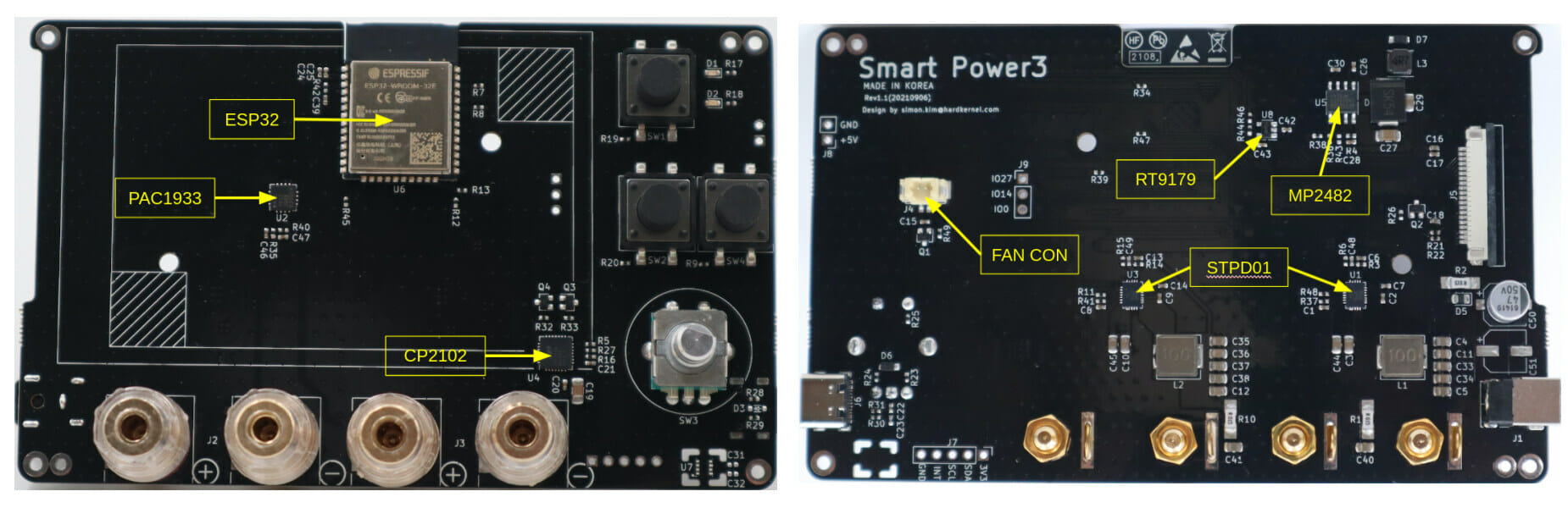
- MCU – ESP32 dual-core microcontroller via ESP32-WROOM-32E module
- Output Channels – 2x output channels (Max 50W + 50W) via 2x 4mm banana jacks each
- Output Voltage – 3V DC to input voltage – 1V
- Output Current – 3A max per channel
- Measurement
- Voltage, Current, Power
- Maximum sampling rate: 200Hz (5msec interval)
- Display – 3.5-inch TFT IPS LCD wide viewing angle, 480×320 resolution
- Host interface – USB Type-C port for connection to PC for data communication and firmware upgrade
- Misc
- Red power LED, Blue “Alive” (Active?) LED
- Buttons – ON/OFF/Menu/Cancel, Output Channel On/Off
- Rotary encoder for voltage and current adjustment, also work as Select/Setup button
- Input Voltage – 9V to 21V DC
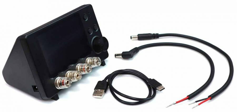 The device ships with a USB-C data cable, and two DC plug cables (5.5/2.1mm) compatible with ODROID-XU4, ODROID-N2, and ODROID-C4. You’ll also need a power supply, and Hardkernel offers an optional 15V/4A PSU that sells for $9.4. A 19V laptop power brick should also work, so in theory, you would not necessarily have to buy an extra power supply.
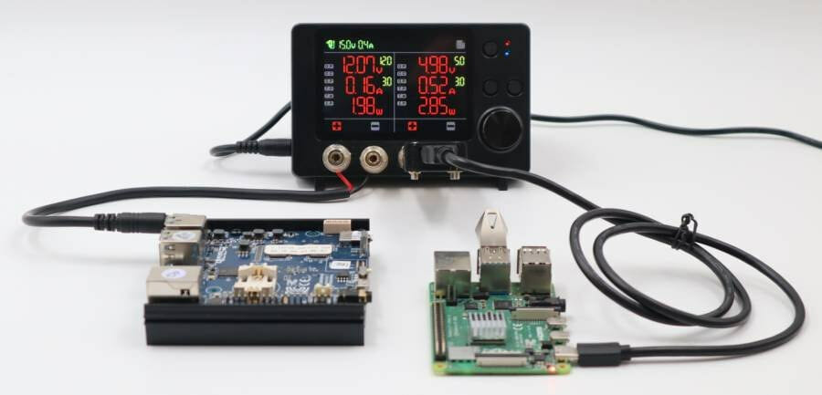
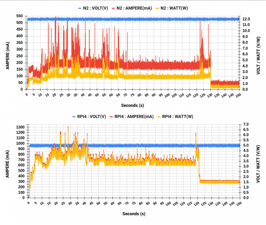
The data is shown in real-time on the display, but the Smart Power 3 is mostly useful thanks to its ability to send data to a host computer. Despite ESP32 supporting WiFi connectivity, the tool only sends data over USB to a serial interface at 921,000 bps (by default). There’s no fancy software to handle the data, and instead, comma-separated values are sent to a serial console program like “GNU Screen”.
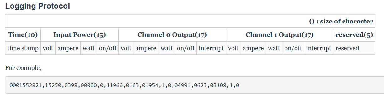 The data received in the terminal can then be saved into a CSV file before being imported into your preferred spreadsheet program for charting and analysis.
It can also be used for eventual voltage drops, and software/hardware could be optimized for applications that eventually aim to run on battery. Although it’s possible to look at the values in real-time in the serial console, the lack of real-time charting is not ideal, so maybe it could be integrated with an open-source solution such as Sigrok/Pulseview or RPI-Monitor if one use an SBC has the host computer.
Implementing data acquisition over WiFi might be interesting too, both for convenience and possibly higher sampling rates (if possible based on the rest of the hardware). The ESP32 firmware used in Smart Power 3 is open-source, so it could also be improved upon. You’ll find more documentation and the firmware source code in the Wiki.
Smart Power 3 tool can be purchased directly for $45 on Hardkernel’s website, and may show up on distributors soon as well. Somehow the power supply is not optional, and at this time, you’d have to add a 15V/4A ($9.4) or a 19V/7A ($25) power adapter to complete your order.

Jean-Luc started CNX Software in 2010 as a part-time endeavor, before quitting his job as a software engineering manager, and starting to write daily news, and reviews full time later in 2011.
Support CNX Software! Donate via cryptocurrencies, become a Patron on Patreon, or purchase goods on Amazon or Aliexpress. We also use affiliate links in articles to earn commissions if you make a purchase after clicking on those links.

Just looked on UK distributor website + vat £62.42 without PSU, with PSU + £15.00
That is before p+p
> maybe it could be integrated with an open-source solution such as Sigrok/Pulseview or RPI-Monitor
That’s quite easy with a few lines in any scripting language. Just read in the serial data continuously, do some sort of averaging and write the last or averaged value into a file you point the graphing software to. If the sampling interval of the latter is much higher than what PowerMeter3 delivers then I would even graph min/avg/max separately.
Just wondering whether Hardkernel chose the protocol to be compatible with powertop’s –extech option?
It is a great price but is not quick enough for wireless applications. Taking as an example the typical SIM800 module, the transmitting burst peaks are around 500uS. This is much faster than the 5msec interval that this device offers, and this is critical for battery-powered applications.
If it’s performing instantanious samples, then you are correct, but if it’s accumulating power used over that interval than it’s not as important.
Looks like it uses a PAC1933 to do the power monitoring and that chip has a power accumulator. So, if you want a reliable power useage, you’re fine. If you think you can multiply the voltage and current samples to get power and accumulate that, you’re probably in for a bad day.
https://www.microchip.com/en-us/product/PAC1933
It is accumulating power, but if the sample rate is, according to the webpage you link, 1024 per second, it is just 1Khz, but not enough.
With the module I am talking about, it is possible to miss the peaks since you need a sample rate at least twice the frequency (according to Nyquist-Shannon theorem), 4k samples / second
But what’s the point of measuring sub-millisecond peaks when you’re supposed to be using decoupling capacitors anyway ?
Is it usable in the uA range?
Nicee, I wonder when they will launch his new tv box.
It would probably be interesting to compare this with Nordic Semi’s Power Profiler Kit II which is in a similar price range (a bit more expensive). No funky LCD, but I think the specs are better for the low-power side of things where it’s probably the most useful. I didn’t try it yet.
The Power Profile Kit is mostly designed for (Nordic Semi) Cortex-M chips, I don’t think Smart Power 3 is useful for ultra-low power chips, while a 1A limit, the Nordic tool is not useful for SBC’s.
only 3V output? I think it’s too low, how to use with 3.3v processor or 5v ?
The output is “3V DC to input voltage – 1V” That means with a 15V power adapter, the range is 3V to 14V, with a 19V power adapter 3V to 18V, etc…
Thank you, I couldn’t understand it.
But, if i have 14V input can i adjust output to 1.8 V ?
I understand 3V is the minimum.
So.. this is a toy.
If somebody want to make an IOT powered from battery then he use 1.8v not 3.3v
I still think RPi4 based solutions with i2c power metering chips might provide higher precision. Of course all sensors need to be calibrated but do they even provide calibration files?
For sure Jerry! If there’s a raspberry painted on the board, the analog parts will measure better, that’s well-known…
I’ve been looking at the design of this Odroid Smart Power3 device for a little while. It is quite interesting, primarily because it uses the “Microchip PAC193X Single/ Multi-Channel DC Power/Energy Monitor with Accumulator” part to collect input data. Here’s where to find the PAC193X data:
* PAC133X Datasheet (64 pages): https://www.microchip.com/content/dam/mchp/documents/OTH/ProductDocuments/DataSheets/PAC1931-Family-Data-Sheet-DS20005850E.pdf
The Odroid Smart Power3 device is completely open so if the price can come down a bit and the requirement to buy a useless power supply is removed, it might spawn a community around it that can improve the design and software and turn the device into a real mini Source-Measure Unit (SMU). Some comments and questions that came to mind:
1. Hardkernel specifies the sample rate as 5ms (200Hz), which is peculiar. The PAC1933 chip on its own has user programmable sample rates of 8, 64, 256, and 1024 samples per second. What’s more, the PAC1933 chip has large self-filling data accumulator registers on-die as well. So what’s limiting the Smart Power3 sample rate to five milliseconds?
2. The PAC193X chips are really designed as energy monitors. As such the data samples are moving averaged plus there’s a normalizing algorithm that removes offsets. It seems like the user cannot turn these things off (though I’m not 100% sure about this yet). If not, this processing of the data is going to obscure transient events, which is not good in an analytical instrument looking at the likes of microcontroller dynamic power consumption.
3. The Odroid Smart Power3 has what I consider to be a critical flaw, the inputs do not have any sample-and-hold capability. This makes it impossible to capture transient events between samples, a capability that is necessary when monitoring microcontroller power consumption. Seeing this I began scouring the PA193X datasheet for some sort of synchronous output from the chip, either a pin or a serial message, that signifies when samples begin and/or end. I did find two alert messages: ALERT on accumulator overflow, and ALERT on Conversion Complete. The alert on conversion message sounds interesting, I’ll have to look into that a bit more. Regardless, adding sample-and-hold will require additional hardware.
5. Why is there no WiFi connectivity? The ESP-WROOM-32E has two processors, can’t it use one for WiFi and the other to control the Smart Power3? At least the code is open so maybe this can be easily fixed.
6. It has a graphical display, but it seems like it can’t even plot one input channel in real-time, weird. But the software is infinitely hackable so I’m looking forward to improvements. Plotting the serial data in real time externally is possible provided the data is output in real-time. There are plenty of PC applications for plotting serial data. For example this free software Serial Oscilloscope can plot up to nine channels with triggers on each channel:
* Serial Oscilloscope for Windows by XIO Technologies:
https://x-io.co.uk/serial-oscilloscope/
https://github.com/xioTechnologies/Serial-Oscilloscope
7. It has a fan – yuck. Fans are not cool. Fans fail, fans are noisy. Ban the fan.
High sample rate and wide dynamic range is critical to measure deep standby and radio communication.
http://www.sistemi.ca/p1125
Disclosure, I designed the P1125.