
Raspberry Pi Trading announced the Raspberry Pi Pico W board basically based on the same design as the original Raspberry Pi Pico board with RP2040 dual-core Cortex-M0+ microcontroller but adding a wireless module with WiFi 4 and Bluetooth LE 5.2, although the latter is not enabled on the board at this time.
The company sent me a sample for review/evaluation, and I’ll focus on the WiFi part since the Raspberry Pi Pico W supports the same MicroPython and C/C++ SDKs as for the Raspberry Pi Pico board plus additional APIs for wireless connectivity.
Raspberry Pi Pico W unboxing
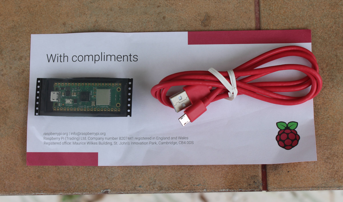
The board I received was cut from a 480-unit reel, and I also got a one-meter long micro USB to USB cable, which should probably not be included by default for people ordering the $6 board.
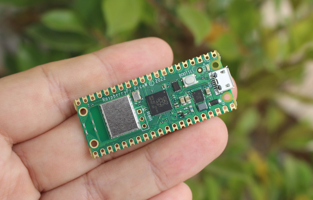
Just like its predecessor, the board is tiny, and
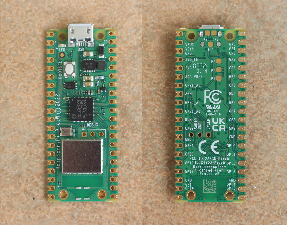
The pinout is the same as the first RP2040 board, and clearly marked on the bottom side of the board.
Connecting Raspberry Pi Pico W to your computer
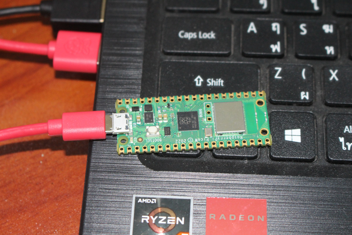
Once we connect the board to the host computer it should show up as the RPI-RP2 drive in your computer. My laptop is running Ubuntu 20.04, but it will be the same on Windows or macOS.
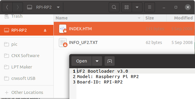
There are two files in the drive with INFO_UF2.txt with some information about the UF2 bootloader version and board model, and INDEX.HTM that redirects to the Pico documentation on the Raspberry Pi website. So nothing has changed here.
Here’s the output from kernel log for reference:
|
1 2 3 4 5 6 7 8 9 10 11 12 13 14 15 16 17 18 19 |
[31039.896573] usb 1-1: new full-speed USB device number 7 using xhci_hcd [31040.068190] usb 1-1: New USB device found, idVendor=2e8a, idProduct=0003, bcdDevice= 1.00 [31040.068198] usb 1-1: New USB device strings: Mfr=1, Product=2, SerialNumber=3 [31040.068201] usb 1-1: Product: RP2 Boot [31040.068203] usb 1-1: Manufacturer: Raspberry Pi [31040.068205] usb 1-1: SerialNumber: E0C9125B0D9B [31040.126291] usb-storage 1-1:1.0: USB Mass Storage device detected [31040.126674] scsi host2: usb-storage 1-1:1.0 [31040.126893] usbcore: registered new interface driver usb-storage [31040.134814] usbcore: registered new interface driver uas [31041.138666] scsi 2:0:0:0: Direct-Access RPI RP2 3 PQ: 0 ANSI: 2 [31041.139090] sd 2:0:0:0: Attached scsi generic sg2 type 0 [31041.139462] sd 2:0:0:0: [sdc] 262144 512-byte logical blocks: (134 MB/128 MiB) [31041.140240] sd 2:0:0:0: [sdc] Write Protect is off [31041.140242] sd 2:0:0:0: [sdc] Mode Sense: 03 00 00 00 [31041.142282] sd 2:0:0:0: [sdc] No Caching mode page found [31041.142290] sd 2:0:0:0: [sdc] Assuming drive cache: write through [31041.150224] sdc: sdc1 [31041.154246] sd 2:0:0:0: [sdc] Attached SCSI removable disk |
WiFi with MicroPython
Raspberry Pi Pico and Pico W share the same bootloader, but the MicroPython firmware is different, possibly due to small hardware differences (e.g. user LED connection), but also because it would not make sense to add the WiFi stack to Raspberry Pi Pico and waste precious storage and memory on a resources-constrained microcontroller.
We’ll find the right firmware file on Raspberry Pi website or we can download it directly as follows:
|
1 |
wget https://micropython.org/download/rp2-pico-w/rp2-pico-w-latest.uf2 |
Once we’ve downloaded it, simply copy rp2-pico-w-latest.uf2 to the RPI-RP2 drive…
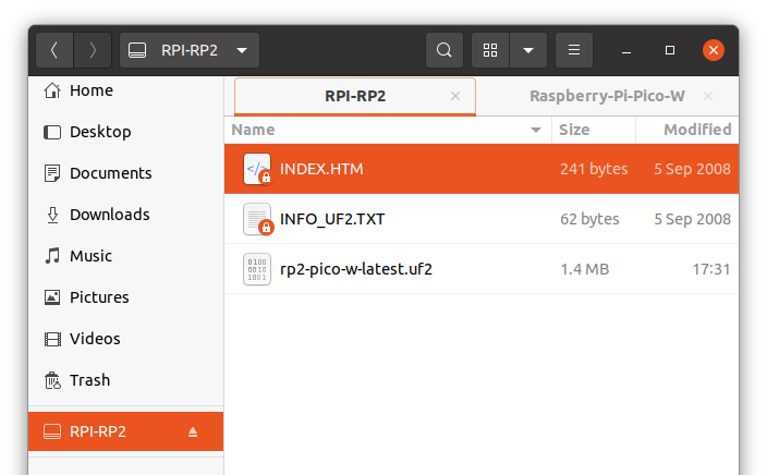
… and soon the drive will disappear, and the Raspberry Pi Pico W will now show as a serial device:
|
1 2 3 4 5 6 7 8 9 |
[31932.896450] usb 1-1: new full-speed USB device number 8 using xhci_hcd [31933.070029] usb 1-1: New USB device found, idVendor=2e8a, idProduct=0005, bcdDevice= 1.00 [31933.070039] usb 1-1: New USB device strings: Mfr=1, Product=2, SerialNumber=3 [31933.070043] usb 1-1: Product: Board in FS mode [31933.070046] usb 1-1: Manufacturer: MicroPython [31933.070049] usb 1-1: SerialNumber: e6614c311b939432 [31933.164647] cdc_acm 1-1:1.0: ttyACM0: USB ACM device [31933.164710] usbcore: registered new interface driver cdc_acm [31933.164714] cdc_acm: USB Abstract Control Model driver for USB modems and ISDN adapters |
Which we can also detect in BootTerm (or other tools like Putty, minicom, tio, etc…):
|
1 2 3 4 |
$ bt -l port | age (sec) | device | driver | description ------+------------+------------+------------------+---------------------- * 0 | 132 | ttyACM0 | cdc_acm | Board CDC |
If we connect to the serial device, we’ll enter a REPL interface where we can type some commands to list the 2.4 GHz access points:
|
1 2 3 4 5 6 7 8 9 10 11 |
$ bt No port specified, using ttyACM0 (last registered). Use -l to list ports. Trying port ttyACM0... Connected to ttyACM0 at 115200 bps. Escape character is 'Ctrl-]'. Use escape followed by '?' for help. >>> import network >>> wlan = network.WLAN(network.STA_IF) >>> wlan.active(True) >>> print(wlan.scan()) [(b'CNX_Software_Xiaomi', b'<\xcdW\xf5\xaf\x92', 8, -24, 5, 5), (b'', b'B\xcdW\xf5\xaf\x92', 8, -26, 0, 2)] >>> |
Great! It works. There’s only one visible access point detected because I live in the countryside. The other value (”) is for a hidden SSID open on my Xiaomi router. According to MicroPython API documentation, the five other values are for the bssid, channel number, RSSI, authmode, and hidden status, but the last two numbers are out of range:
There are five values for security:
- 0 – open
- 1 – WEP
- 2 – WPA-PSK
- 3 – WPA2-PSK
- 4 – WPA/WPA2-PSK
and two for hidden:
- 0 – visible
- 1 – hidden
To go further, we’ll look at the “Connecting to the Internet” documentation for the board. The easiest way to update the code it to install Thonny editor first:
|
1 2 |
sudo apt install python3-tk pip3 install thonny |
We can run the previous MicroPython program in Thonny IDE without any issue after going to Run->Select Interpreter and selecting “MicroPython (Raspberry Pi Pico)”
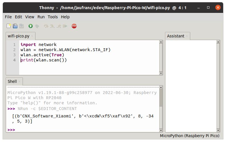
Let’s connect to CNX_Software_Xiaomi SSID with the following program:
|
1 2 3 4 5 6 7 8 9 10 11 12 13 14 15 16 17 18 19 20 21 22 23 24 25 26 |
import time import network ssid = 'CNX_Software_Xiaomi' password = 'The Password' wlan = network.WLAN(network.STA_IF) wlan.active(True) wlan.connect(ssid, password) # Wait for connect or fail max_wait = 10 while max_wait > 0: if wlan.status() < 0 or wlan.status() >= 3: break max_wait -= 1 print('waiting for connection...') time.sleep(1) # Handle connection error if wlan.status() != 3: raise RuntimeError('network connection failed') else: print('connected') status = wlan.ifconfig() print( 'ip = ' + status[0] ) |
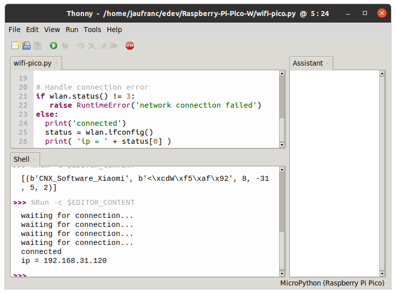
My Raspberry Pi Pico W got an IP address and I can ping it successfully:
|
1 2 3 4 5 6 |
$ ping 192.168.31.120 PING 192.168.31.120 (192.168.31.120) 56(84) bytes of data. 64 bytes from 192.168.31.120: icmp_seq=1 ttl=255 time=187 ms 64 bytes from 192.168.31.120: icmp_seq=2 ttl=255 time=35.3 ms 64 bytes from 192.168.31.120: icmp_seq=3 ttl=255 time=54.1 ms 64 bytes from 192.168.31.120: icmp_seq=4 ttl=255 time=77.1 ms |
For reference, it shows as PYPB on the network:
|
1 2 3 4 5 6 |
$ nmap -sP 192.168.31.0/24 Starting Nmap 7.80 ( https://nmap.org ) at 2022-07-02 14:04 +07 ... Nmap scan report for PYBD (192.168.31.120) Host is up (0.026s latency). ... |
The firmware ships with safe, global settings, but you may enable extra channels by setting up the country:
|
1 2 |
import rp2 rp2.country('TH') |
This will be especially useful if your board fails to connect to your router due to unavailable channels.
A typical use case for this type of board is to have a web interface to control LEDs or GPIOs. Let’s run a web server to control the user LED on the board:
|
1 2 3 4 5 6 7 8 9 10 11 12 13 14 15 16 17 18 19 20 21 22 23 24 25 26 27 28 29 30 31 32 33 34 35 36 37 38 39 40 41 42 43 44 45 46 47 48 49 50 51 52 53 54 55 56 57 58 59 60 61 62 63 64 65 66 67 68 69 70 71 72 73 74 75 76 77 78 79 80 81 |
import network import socket import time from machine import Pin # Select the onboard LED led = machine.Pin("LED", machine.Pin.OUT) ssid = 'CNX_Software_Xiaomi' password = 'A Password' wlan = network.WLAN(network.STA_IF) wlan.active(True) wlan.connect(ssid, password) html = """<!DOCTYPE html> <html> <head> <title>CNX Software's Pico W </title> </head> <body> <h1>CNX Software's Pico W</h1> <p>%s</p> </body> </html> """ # Wait for connect or fail max_wait = 10 while max_wait > 0: if wlan.status() < 0 or wlan.status() >= 3: break max_wait -= 1 print('waiting for connection...') time.sleep(1) # Handle connection error if wlan.status() != 3: raise RuntimeError('network connection failed') else: print('connected') status = wlan.ifconfig() print( 'ip = ' + status[0] ) # Open socket addr = socket.getaddrinfo('0.0.0.0', 80)[0][-1] s = socket.socket() s.bind(addr) s.listen(1) print('listening on', addr) # Listen for connections while True: try: cl, addr = s.accept() print('client connected from', addr) request = cl.recv(1024) print(request) request = str(request) led_on = request.find('/light/on') led_off = request.find('/light/off') print( 'led on = ' + str(led_on)) print( 'led off = ' + str(led_off)) if led_on == 6: print("led on") led.value(1) stateis = "LED is ON" if led_off == 6: print("led off") led.value(0) stateis = "LED is OFF" response = html % stateis cl.send('HTTP/1.0 200 OK\r\nContent-type: text/html\r\n\r\n') cl.send(response) cl.close() except OSError as e: cl.close() print('connection closed') |
The code is a little long as it includes some error handling as well. It works fine as you can see from the short demo video below.

The code could be easily modified to control relays or GPIOs.
It’s also possible to install and run the popular iperf3 tool on the Raspberry Pi Pico W:
|
1 2 3 4 5 6 7 8 |
import network wlan = network.WLAN(network.STA_IF) wlan.active(True) wlan.connect('CNX_Software_Xiaomi', 'The Password') import upip upip.install("uiperf3") import uiperf3 uiperf3.client('192.168.31.48') |
The code is rather short because we’ve skipped error handling for the connection. Anyway here’s the output from the network benchmark test:
|
1 2 3 4 5 6 7 8 9 10 11 12 13 14 15 |
Connecting to ('192.168.31.48', 5201) Interval Transfer Bitrate 0.00-1.00 sec 492 KBytes 4.03 Mbits/sec 1.00-2.00 sec 552 KBytes 4.51 Mbits/sec 2.00-3.00 sec 587 KBytes 4.80 Mbits/sec 3.00-4.00 sec 579 KBytes 4.74 Mbits/sec 4.00-5.00 sec 567 KBytes 4.65 Mbits/sec 5.00-6.00 sec 521 KBytes 4.26 Mbits/sec 6.00-7.00 sec 551 KBytes 4.51 Mbits/sec 7.00-8.00 sec 563 KBytes 4.61 Mbits/sec 8.00-9.00 sec 564 KBytes 4.61 Mbits/sec 9.00-10.00 sec 533 KBytes 4.38 Mbits/sec - - - - - - - - - - - - - - - - - - - - - - - - - - - - - - 0.00-10.00 sec 5.38 MBytes 4.51 Mbits/sec sender 0.00-10.85 sec 5.38 MBytes 4.16 Mbits/sec receiver |
That looks fairly slow to me, even though performance is not always the main requirement on this type of platform. It may also be typical (for this benchmark) on this class of hardware as, for reference, Damien George (MicroPython’s main developer) tested it on the Pyboard D-series board and achieved around 7 Mbits/sec.
If the announcement we were told the Raspberry Pi Pico W can also be used as an access point with up to four clients. I did not find any tutorial for this in MicroPython, but there are instructions for ESP8266 and ESP32, so let’s try to setup a CNX-PICO SSID and connect from a phone:
|
1 2 3 4 5 6 |
import network ssid = 'CNX-PICO' password = 'cnx-review' ap.config(essid=ssid, password=password ap = network.WLAN(network.AP_IF) ap.active(True) |
The good news is that my Raspberry Pi Pico W is now indeed an access point, but the less good news is that the custom ssid configuration did not work, and instead the board will automatically generate an access point name (PICO349B) with an open network.
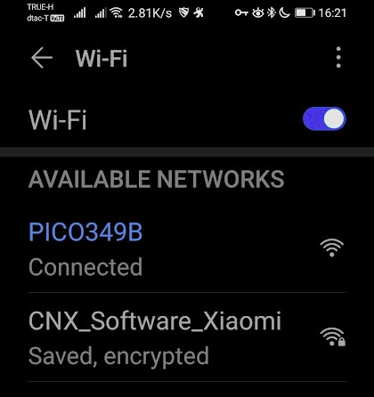
So the API must be different, or custom access point names are not supported on Raspberry Pi Pico W MicroPython firmware just yet.
Using WiFi on Raspberry Pi Pico W with C programming
Let’s try to reproduce the code samples above with the C/C++ SDK. If you haven’t done so already, you’ll need to set up the SDK as we did for the Raspberry Pi Pico board and get the samples in a Linux computer or Raspberry Pi board:
|
1 2 3 4 5 6 |
sudo apt install cmake gcc-arm-none-eabi libnewlib-arm-none-eabi build-essential git clone https://github.com/raspberrypi/pico-sdk cd pico-sdk git submodule update --init cd .. git clone -b master https://github.com/raspberrypi/pico-examples.git |
There’s now a new directory for Pico W:
|
1 2 3 4 5 6 7 8 9 10 11 12 13 |
$ ls -l pico-examples/pico_w/ total 44 drwxrwxr-x 3 jaufranc jaufranc 4096 Jul 2 16:32 access_point drwxrwxr-x 2 jaufranc jaufranc 4096 Jul 2 16:32 blink -rw-rw-r-- 1 jaufranc jaufranc 985 Jul 2 16:32 CMakeLists.txt drwxrwxr-x 4 jaufranc jaufranc 4096 Jul 2 16:32 freertos drwxrwxr-x 2 jaufranc jaufranc 4096 Jul 2 16:32 iperf -rw-rw-r-- 1 jaufranc jaufranc 3417 Jul 2 16:32 lwipopts_examples_common.h drwxrwxr-x 2 jaufranc jaufranc 4096 Jul 2 16:32 ntp_client drwxrwxr-x 2 jaufranc jaufranc 4096 Jul 2 16:32 python_test_tcp drwxrwxr-x 2 jaufranc jaufranc 4096 Jul 2 16:32 tcp_client drwxrwxr-x 2 jaufranc jaufranc 4096 Jul 2 16:32 tcp_server drwxrwxr-x 2 jaufranc jaufranc 4096 Jul 2 16:32 wifi_scan |
Here’s the WiFi scan sample code:
|
1 2 3 4 5 6 7 8 9 10 11 12 13 14 15 16 17 18 19 20 21 22 23 24 25 26 27 28 29 30 31 32 33 34 35 36 37 38 39 40 41 42 43 44 45 46 47 48 49 50 51 52 53 54 55 56 57 58 59 60 61 62 63 64 65 66 67 68 69 |
** * Copyright (c) 2022 Raspberry Pi (Trading) Ltd. * * SPDX-License-Identifier: BSD-3-Clause */ #include <stdio.h> #include "pico/stdlib.h" #include "pico/cyw43_arch.h" static int scan_result(void *env, const cyw43_ev_scan_result_t *result) { if (result) { printf("ssid: %-32s rssi: %4d chan: %3d mac: %02x:%02x:%02x:%02x:%02x:%02x sec: %u\n", result->ssid, result->rssi, result->channel, result->bssid[0], result->bssid[1], result->bssid[2], result->bssid[3], result->bssid[4], result->bssid[5], result->auth_mode); } return 0; } #include "hardware/vreg.h" #include "hardware/clocks.h" int main() { stdio_init_all(); if (cyw43_arch_init()) { printf("failed to initialise\n"); return 1; } cyw43_arch_enable_sta_mode(); absolute_time_t scan_test = nil_time; bool scan_in_progress = false; while(true) { if (absolute_time_diff_us(get_absolute_time(), scan_test) < 0) { if (!scan_in_progress) { cyw43_wifi_scan_options_t scan_options = {0}; int err = cyw43_wifi_scan(&cyw43_state, &scan_options, NULL, scan_result); if (err == 0) { printf("\nPerforming wifi scan\n"); scan_in_progress = true; } else { printf("Failed to start scan: %d\n", err); scan_test = make_timeout_time_ms(10000); // wait 10s and scan again } } else if (!cyw43_wifi_scan_active(&cyw43_state)) { scan_test = make_timeout_time_ms(10000); // wait 10s and scan again scan_in_progress = false; } } // the following #ifdef is only here so this same example can be used in multiple modes; // you do not need it in your code #if PICO_CYW43_ARCH_POLL // if you are using pico_cyw43_arch_poll, then you must poll periodically from your // main loop (not from a timer) to check for WiFi driver or lwIP work that needs to be done. cyw43_arch_poll(); sleep_ms(1); #else // if you are not using pico_cyw43_arch_poll, then WiFI driver and lwIP work // is done via interrupt in the background. This sleep is just an example of some (blocking) // work you might be doing. sleep_ms(1000); #endif } cyw43_arch_deinit(); return 0; } |
That’s a bit more complex than our MicroPython sample above. Let’s prepare the system to build the C samples:
|
1 2 3 4 5 |
cd pico-examples/ mkdir build cd build export PICO_SDK_PATH=../../pico-sdk cmake -DPICO_BOARD=pico_w -DWIFI_SSID="Your Network" -DWIFI_PASSWORD="Your Password" .. |
You’d obviously need to change the SSID and password to match the ones in your network Here’s the output from the command for reference:
|
1 2 3 4 5 6 7 8 9 10 11 12 13 14 15 16 17 18 19 20 21 22 23 24 |
Using PICO_SDK_PATH from environment ('../../pico-sdk') PICO_SDK_PATH is /home/jaufranc/edev/Raspberry-Pi-Pico-W/pico-sdk Defaulting PICO_PLATFORM to rp2040 since not specified. Defaulting PICO platform compiler to pico_arm_gcc since not specified. -- Defaulting build type to 'Release' since not specified. PICO compiler is pico_arm_gcc -- The C compiler identification is GNU 9.2.1 -- The CXX compiler identification is GNU 9.2.1 -- The ASM compiler identification is GNU -- Found assembler: /usr/bin/arm-none-eabi-gcc Build type is Release PICO target board is pico_w. Using CMake board configuration from /home/jaufranc/edev/Raspberry-Pi-Pico-W/pico-sdk/src/boards/pico_w.cmake Using board configuration from /home/jaufranc/edev/Raspberry-Pi-Pico-W/pico-sdk/src/boards/include/boards/pico_w.h -- Found Python3: /usr/bin/python3.8 (found version "3.8.10") found components: Interpreter TinyUSB available at /home/jaufranc/edev/Raspberry-Pi-Pico-W/pico-sdk/lib/tinyusb/src/portable/raspberrypi/rp2040; enabling build support for USB. cyw43-driver available at /home/jaufranc/edev/Raspberry-Pi-Pico-W/pico-sdk/lib/cyw43-driver lwIP available at /home/jaufranc/edev/Raspberry-Pi-Pico-W/pico-sdk/lib/lwip Enabling build support for Pico W wireless. Skipping tcp_client example as TEST_TCP_SERVER_IP is not defined Skipping Pico W FreeRTOS examples as FREERTOS_KERNEL_PATH not defined -- Configuring done -- Generating done -- Build files have been written to: /home/jaufranc/edev/Raspberry-Pi-Pico-W/pico-examples/build |
We can now build the wifi_scan sample:
|
1 2 |
cd pico_w/wifi_scan make -j8 |
The output is fairly long but should start and end as follows:
|
1 2 3 4 5 6 7 8 9 10 11 12 13 14 15 16 17 18 |
Scanning dependencies of target ELF2UF2Build [ 0%] Creating directories for 'ELF2UF2Build' [ 0%] No download step for 'ELF2UF2Build' [ 0%] No patch step for 'ELF2UF2Build' [ 0%] No update step for 'ELF2UF2Build' [ 0%] Performing configure step for 'ELF2UF2Build' -- The C compiler identification is GNU 9.4.0 -- The CXX compiler identification is GNU 9.4.0 -- Check for working C compiler: /usr/bin/cc -- Check for working C compiler: /usr/bin/cc -- works ... [100%] Building C object pico_w/wifi_scan/CMakeFiles/picow_wifi_scan_background.dir/home/jaufranc/edev/Raspberry-Pi-Pico-W/pico-sdk/lib/lwip/src/netif/ppp/polarssl/md5.c.obj [100%] Building C object pico_w/wifi_scan/CMakeFiles/picow_wifi_scan_background.dir/home/jaufranc/edev/Raspberry-Pi-Pico-W/pico-sdk/lib/lwip/src/netif/ppp/polarssl/sha1.c.obj [100%] Building C object pico_w/wifi_scan/CMakeFiles/picow_wifi_scan_background.dir/home/jaufranc/edev/Raspberry-Pi-Pico-W/pico-sdk/src/rp2_common/pico_lwip/nosys.c.obj [100%] Linking CXX executable picow_wifi_scan_background.elf [100%] Built target picow_wifi_scan_background |
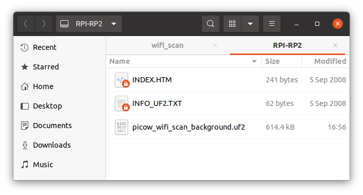
The build will have generated a bunch of files including the UF2 file we’ll use to copy to the board:
|
1 2 3 4 5 6 7 8 9 10 11 12 13 14 15 16 17 |
$ ls -l total 8560 drwxrwxr-x 4 jaufranc jaufranc 4096 Jul 2 16:48 CMakeFiles -rw-rw-r-- 1 jaufranc jaufranc 1027 Jul 2 16:48 cmake_install.cmake -rw-rw-r-- 1 jaufranc jaufranc 482519 Jul 2 16:48 Makefile -rwxrwxr-x 1 jaufranc jaufranc 306968 Jul 2 16:51 picow_wifi_scan_background.bin -rw-rw-r-- 1 jaufranc jaufranc 1499022 Jul 2 16:51 picow_wifi_scan_background.dis -rwxrwxr-x 1 jaufranc jaufranc 380952 Jul 2 16:51 picow_wifi_scan_background.elf -rw-rw-r-- 1 jaufranc jaufranc 452605 Jul 2 16:51 picow_wifi_scan_background.elf.map -rw-rw-r-- 1 jaufranc jaufranc 863499 Jul 2 16:51 picow_wifi_scan_background.hex -rw-rw-r-- 1 jaufranc jaufranc 614400 Jul 2 16:51 picow_wifi_scan_background.uf2 -rwxrwxr-x 1 jaufranc jaufranc 308304 Jul 2 16:51 picow_wifi_scan_poll.bin -rw-rw-r-- 1 jaufranc jaufranc 1490453 Jul 2 16:51 picow_wifi_scan_poll.dis -rwxrwxr-x 1 jaufranc jaufranc 418272 Jul 2 16:51 picow_wifi_scan_poll.elf -rw-rw-r-- 1 jaufranc jaufranc 437754 Jul 2 16:51 picow_wifi_scan_poll.elf.map -rw-rw-r-- 1 jaufranc jaufranc 867250 Jul 2 16:51 picow_wifi_scan_poll.hex -rw-rw-r-- 1 jaufranc jaufranc 616960 Jul 2 16:51 picow_wifi_scan_poll.uf2 |
Since we’ve already installed the MicroPython firmware on the board, We’ll need to press the BOOT button and power cycle the board to enter mass storage mode and copy picow_wifi_scan_poll.uf2 file to the RPI-RP2 drive.
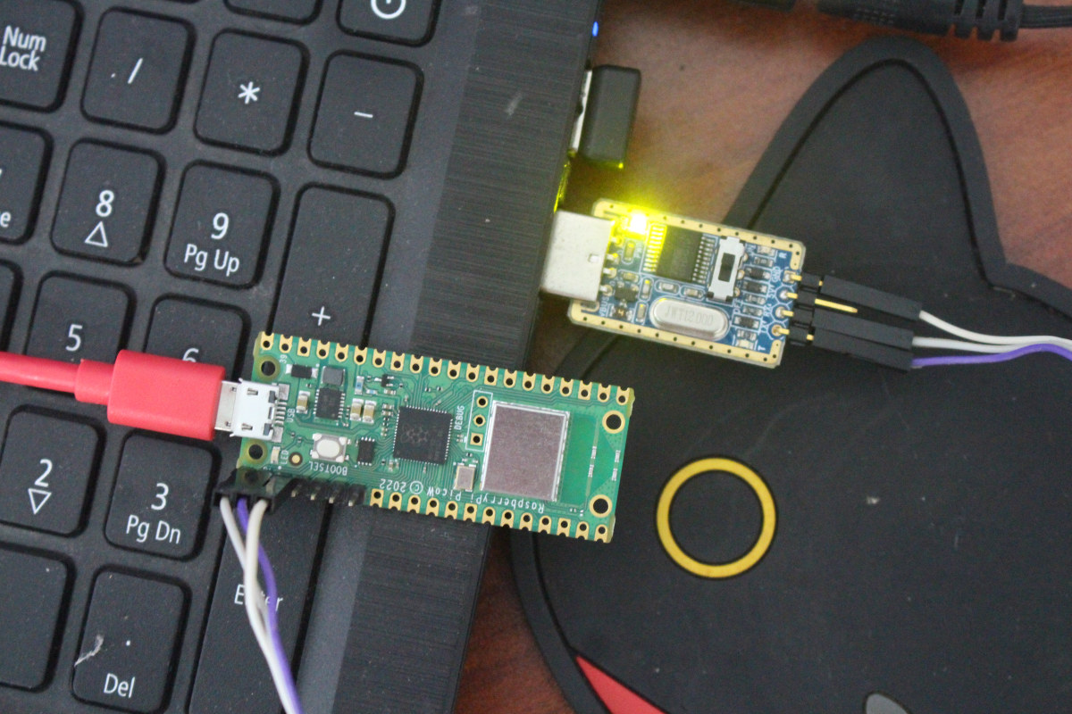
The drive will disappear to reboot and automatically start the program, but I noticed the board will not show as a serial device anymore. That’s because we need to access the serial console through the UART pins of the Raspberry Pi Pico W with pin 1 Tx, pin 2 Rx, and pin 3 GND. So I soldered a short header to the relevant pins on Raspberry Pi Pico W and I used a USB to TTL board connected to my laptop, but if you’re programming the Pico W board with a Raspberry Pi SBC you could use the UART from the 40-pin GPIO header instead.
Now I can use BootTerm and see CNX_Software_Xiaomi SSID and the hidden SSID from my router properly detected:
|
1 2 3 4 5 6 7 8 9 10 11 12 13 14 15 |
$ bt -n 0 ports found, waiting for a new one... port | age (sec) | device | driver | description ------+------------+------------+------------------+---------------------- 0 | 0 | ttyUSB0 | ch341-uart | USB2.0-Serial Trying port ttyUSB0... Connected to ttyUSB0 at 115200 bps. Escape character is 'Ctrl-]'. Use escape followed by '?' for help. Performing wifi scan ssid: rssi: -35 chan: 8 mac: 42:cd:57:f5:af:92 sec: 0 ssid: CNX_Software_Xiaomi rssi: -36 chan: 8 mac: 3c:cd:57:f5:af:92 sec: 5 ssid: CNX_Software_Xiaomi rssi: -35 chan: 8 mac: 3c:cd:57:f5:af:92 sec: 5 ssid: CNX_Software_Xiaomi rssi: -33 chan: 8 mac: 3c:cd:57:f5:af:92 sec: 5 ssid: rssi: -34 chan: 8 mac: 42:cd:57:f5:af:92 sec: 0 |
So scanning works (although it shows the same SSID several times), and we can now try to connect to our WiFi router using the following sample (from Pico W documentation) in wifi_connect/wifi_connect.c:
|
1 2 3 4 5 6 7 8 9 10 11 12 13 14 15 16 17 18 19 20 21 22 23 24 |
#include <stdio.h> #include "pico/stdlib.h" #include "pico/cyw43_arch.h" char ssid[] = "CNX_Software_Xiaomi"; char pass[] = "A Password"; int main() { stdio_init_all(); if (cyw43_arch_init_with_country(CYW43_COUNTRY_UK)) { printf("failed to initialise\n"); return 1; } printf("initialised\n"); cyw43_arch_enable_sta_mode(); if (cyw43_arch_wifi_connect_timeout_ms(ssid, pass, CYW43_AUTH_WPA2_AES_PSK, 10000)) { printf("failed to connect\n"); return 1; } printf("connected\n"); } |
Just make sure you change the ssid and pass values, as well as the country (CYW43_COUNTRY_??). We’ll also need a CMakeLists.txt file:
|
1 2 3 4 5 6 7 8 9 10 11 12 13 14 |
cmake_minimum_required(VERSION 3.13) include(pico_sdk_import.cmake) project(test_project C CXX ASM) set(CMAKE_C_STANDARD 11) set(CMAKE_CXX_STANDARD 17) pico_sdk_init() add_executable(wifi_connect wifi_connect.c ) pico_enable_stdio_usb(wifi_connect 1) pico_enable_stdio_uart(wifi_connect 1) pico_add_extra_outputs(wifi_connect) target_include_directories(wifi_connect PRIVATE ${CMAKE_CURRENT_LIST_DIR} ) target_link_libraries(wifi_connect pico_cyw43_arch_lwip_threadsafe_background pico_stdlib) |
We’ll also need to copy some extra files to your working directory:
|
1 2 |
cp ../../../pico-sdk/external/pico_sdk_import.cmake . cp ../lwipopts_examples_common.h lwipopts.h |
You should now have four files in the folder:
|
1 2 3 4 5 6 |
jaufranc@cnx-laptop-4:~/edev/Raspberry-Pi-Pico-W/pico-examples/pico_w/wifi_connect$ ls -l total 16 -rw-rw-r-- 1 jaufranc jaufranc 480 Jul 3 11:59 CMakeLists.txt -rw-rw-r-- 1 jaufranc jaufranc 3417 Jul 3 12:01 lwipopts.h -rw-rw-r-- 1 jaufranc jaufranc 3165 Jul 3 12:00 pico_sdk_import.cmake -rw-rw-r-- 1 jaufranc jaufranc 519 Jul 3 11:55 wifi_connect.c |
We can now build the program as we did before:
|
1 2 3 4 5 |
mkdir build cd build export PICO_SDK_PATH=../../../../pico-sdk/ cmake -DPICO_BOARD=pico_w .. make -j8 |
If there is any issue during the cmake step, simply correct the CMakeLists.txt file and delete all files in the build folder before running the cmake command again.
Since I’m in Thailand, I first assumed CYW43_COUNTRY_TH would do. Wrong!:
|
1 2 3 4 5 |
/home/jaufranc/edev/Raspberry-Pi-Pico-W/pico-examples/pico_w/wifi_connect/wifi_connect.c:11:36: error: 'CYW43_COUNTRY_TH' undeclared (first use in this function); did you mean 'CYW43_COUNTRY_UK'? 11 | if (cyw43_arch_init_with_country(CYW43_COUNTRY_TH)) { | ^~~~~~~~~~~~~~~~ | CYW43_COUNTRY_UK /home/jaufranc/edev/Raspberry-Pi-Pico-W/pico-examples/pico_w/wifi_connect/wifi_connect.c:11:36: note: each undeclared identifier is reported only once for each function it appears in |
The available countries are available in pico-sdk/lib/cyw43-driver/src/cyw43_country.h. Here’s an extract:
|
1 2 3 4 5 6 7 |
... #define CYW43_COUNTRY_SWITZERLAND CYW43_COUNTRY('C', 'H', 0) #define CYW43_COUNTRY_TAIWAN CYW43_COUNTRY('T', 'W', 0) #define CYW43_COUNTRY_THAILAND CYW43_COUNTRY('T', 'H', 0) #define CYW43_COUNTRY_TURKEY CYW43_COUNTRY('T', 'R', 0) #define CYW43_COUNTRY_UK CYW43_COUNTRY('G', 'B', 0) #define CYW43_COUNTRY_USA CYW43_COUNTRY('U', 'S', 0) |
I see. I have to use CYW43_COUNTRY_THAILAND instead and the build could complete. We have the required UF2 file:
|
1 2 |
ls -l *.uf2 -rw-rw-r-- 1 jaufranc jaufranc 638976 Jul 3 14:00 wifi_connect.uf2 |
Let’s flash it to the board with the usual method, and see if we can indeed connect to the router:
|
1 2 3 4 5 6 7 8 9 |
$ bt -n 1 ports found, waiting for a new one... port | age (sec) | device | driver | description ------+------------+------------+------------------+---------------------- 1 | 0 | ttyACM0 | cdc_acm | Board CDC Trying port ttyACM0... Connected to ttyACM0 at 115200 bps. Escape character is 'Ctrl-]'. Use escape followed by '?' for help. connected |
That does not tell us much, but at least the program runs without error. Working in C with the Raspberry Pi Pico W will require some work both in terms of learning the new low-level CYW43 API, LWiP library, and even playing with FreeRTOS for more complex examples.
There’s no sample to run a webpage to control an LED, so let’s check out the iperf sample. Let’s go into the /pico-examples/build/pico_w/iperf folder, and build the sample:
|
1 |
make -j8 |
In that case, we have two UF2 files:
|
1 2 3 |
$ ls -l *.uf2 -rw-rw-r-- 1 jaufranc jaufranc 629760 Jul 3 14:28 picow_iperf_server_background.uf2 -rw-rw-r-- 1 jaufranc jaufranc 632832 Jul 3 14:28 picow_iperf_server_poll.uf2 |
If we look at the code this is selected through PICO_CYW43_ARCH_POLL:
- PICO_CYW43_ARCH_POLL = 1 – if you are using pico_cyw43_arch_poll, then you must poll periodically from your main loop (not from a timer) to check for WiFi driver or lwIP work that needs to be done.
- PICO_CYW43_ARCH_POLL != 1 – if you are not using pico_cyw43_arch_poll, then WiFI driver and lwIP work is done via interrupt in the background. This sleep is just an example of some (blocking)
Those are just two different programming methods for the program flow either using polling or interrupt. The latter is normally more efficient, but more complex. I’ll just copy picow_iperf_server_background.uf2 to the board for testing. Note the implementation is based on iperf2, not iperf3 as with the MicroPython example. The iperf server is running on the Raspberry Pi Pico W:
|
1 2 3 4 5 6 7 8 9 10 11 12 |
$ bt -n 1 ports found, waiting for a new one... port | age (sec) | device | driver | description ------+------------+------------+------------------+---------------------- 0 | 0 | ttyUSB0 | ch341-uart | USB2.0-Serial Trying port ttyUSB0... Connected to ttyUSB0 at 115200 bps. Escape character is 'Ctrl-]'. Use escape followed by '?' for help. Connecting to WiFi... Connected. Ready, running iperf server at 192.168.31.120 |
Let’s run iperf client on the laptop:
|
1 2 3 4 5 6 7 8 |
jaufranc@cnx-laptop-4:~$ iperf -c 192.168.31.120 ------------------------------------------------------------ Client connecting to 192.168.31.120, TCP port 5001 TCP window size: 85.0 KByte (default) ------------------------------------------------------------ [ 3] local 192.168.31.48 port 50008 connected with 192.168.31.120 port 5001 [ ID] Interval Transfer Bandwidth [ 3] 0.0-10.0 sec 9.75 MBytes 8.15 Mbits/sec |
8 Mbps that a bit better than with MicroPython, but still in the same ballpark. The result is also shown in the Pico W serial console:
|
1 2 |
Completed iperf transfer of 9 MBytes @ 8.1 Mbits/sec Total iperf megabytes since start 9 Mbytes |
If you want to run the iperf sample as a client on Pico W you’ll need to add the following two lines after the headers:
|
1 2 |
#define CLIENT_TEST 1 #define IPERF_SERVER_IP <IP_address of the server> |
This “Getting Started Guide” is getting long and has a bit more details than I initially expected, so I’ll skip that part.
Let’s complete the WiFi tutorial with the access point demo for Raspberry Pi Pico W. Before building the sample, we’ll want to have a look at the code in pico-examples/pico_w/access_point/picow_access_point.c:
|
1 2 3 4 5 6 7 8 9 10 11 12 13 14 15 16 |
const char *ap_name = "picow_test"; #if 1 const char *password = "password"; #else const char *password = NULL; #endif cyw43_arch_enable_ap_mode(ap_name, password, CYW43_AUTH_WPA2_AES_PSK); ip4_addr_t gw, mask; IP4_ADDR(&gw, 192, 168, 4, 1); IP4_ADDR(&mask, 255, 255, 255, 0); // Start the dhcp server dhcp_server_t dhcp_server; dhcp_server_init(&dhcp_server, &gw, &mask); |
This part is in the main() function. We can see that by default the SSID (access point name0 is picow_test, the password is password (with WPA2 security), the subnet will be 192.168.4.0, and the program will also start a DHCP server so that the client can get an IP address. If you set the password to NULL, it should become an open network. Let’s changed the ap_name to picow_cnxsoft, and the password to 123456…
|
1 2 3 4 5 6 |
const char *ap_name = "picow_cnxsoft"; #if 1 const char *password = "123465"; #else const char *password = NULL; #endif |
Let’s build the sample and copy picow_access_point_poll.uf2 or picow_access_point_background.uf2 to the board as usual. Here’s the output from the terminal:
|
1 2 3 4 5 |
$ bt No port specified, using ttyUSB0 (last registered). Use -l to list ports. Trying port ttyUSB0... Connected to ttyUSB0 at 115200 bps. Escape character is 'Ctrl-]'. Use escape followed by '?' for help. Starting server on port 80 |
The server on port 80 is not a web server, but instead, a basic TCP server that I suppose is meant to work with the TCP client sample installed on another Raspberry Pi Pico.
Nevertheless, I could connect my phone to the picow_cnxsoft access point…
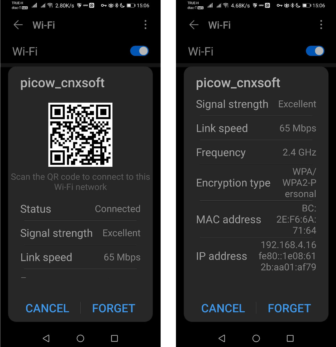
as well as my Ubuntu laptop
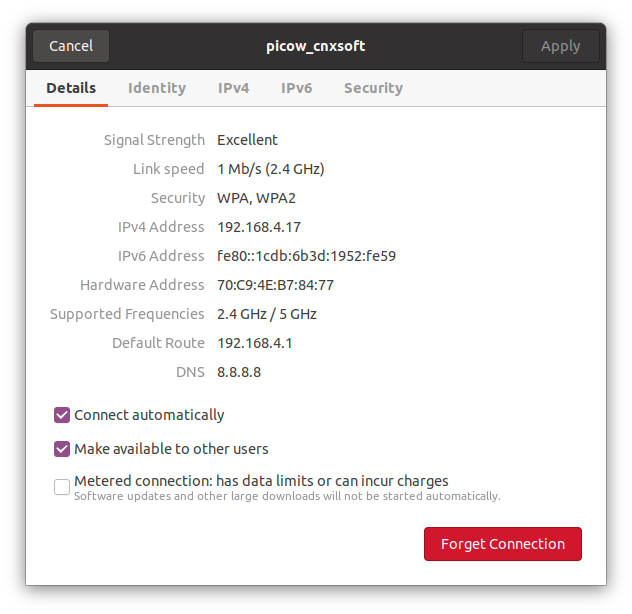
Both devices also show up in Raspberry Pi Pico W’s serial terminal:
|
1 2 3 |
Starting server on port 80 DHCPS: client connected: MAC=bc:2e:f6:6a:71:64 IP=192.168.4.16 DHCPS: client connected: MAC=70:c9:4e:b7:84:77 IP=192.168.4.17 |
Raspberry Pi Pico W’s documentation is pretty good to get started with WiFi, but not necessarily complete, as for example, at this time there’s no example to set up an access point in MicroPython and be prepared to look into the code, for example, I had to look into the code in the C/C++ SDK, as opposed as to the documentation, to find country settings. Most people should probably get started with MicroPython, as while the C/C++ SDK is more flexible, the learning curve should be much steeper.

Jean-Luc started CNX Software in 2010 as a part-time endeavor, before quitting his job as a software engineering manager, and starting to write daily news, and reviews full time later in 2011.
Support CNX Software! Donate via cryptocurrencies, become a Patron on Patreon, or purchase goods on Amazon or Aliexpress. We also use affiliate links in articles to earn commissions if you make a purchase after clicking on those links.


Are the 3x same ssids maybe 2.4 and 5ghz and iot radio of your Xiaomi router?
I was confused by that as well with the C wifi scan sample. The MicroPython WiFi scan sample does not have this issue. I don’t think the Pico W module supports 5.0 GHz at all, so I don’t have an explanation for now.
Love the post, helped me get my Pico W online! The solution to the SSID not setting as you experienced is to call config on the ap before setting it as active.
> The solution to the SSID not setting as you experienced is to call config on the ap before setting it as active
I thought I had tried that, but I’ll check it again a bit later.
I had a similar issue on esp32, the solution in my case was to make sure the ssid was at least 8 characters long.
Learning curse?
Hi Jean-Luc @ CNX
will there be a followup about
PICO W
but using
Circuit Python?
i got mine just 2 days ago and today find your good article
PICO W use MicroPython OR C++SDK
will start to dive in.
b.r. KLL
There’s a beta image of CircuitPython for Raspberry Pi Pico W @ https://circuitpython.org/board/raspberry_pi_pico_w/
I haven’t tried it.
For everybody who wants to start with PlatformIO and the Pico W: to make everything work smoothly, your platformio.ini should look like this:
I was looking for a guide on how to set up the PicoW as a webserver, host a simple webpage to control stuff, and I wanted the Pico to act as an accesspoint at the same time.
Finally, by looking at various examples I now managed to put together a script that does this. One of the scripts I learned from also did read and displayed the Pico temp sensor at the webpage, so I have made this script include that as well.
The script below works, but I would like to improve the html layout later. Like how to make that temperaure to apear on a separate line, and also what to do if I want to have some more buttons to control multiple outputs.
If anyone have any suggestions on how to do that, please feel free to comment.
I did some minor changes to add another set of buttons, and made them now control the GP0 and GP1 outputs instead of the onboard LED. The button pairs are now put side by side instead of on top of each other.
I still need to figure out how to split the stateis information into multiple lines so that it can show one line for each IO and one line for Temperature.
import rp2
import network
import machine
import socket
from time import sleep_ms
from picozero import pico_temp_sensor, pico_led
ssid = “pico_w_ap”
password = “12345678”
ap = network.WLAN(network.AP_IF)
ap.config(essid=ssid, password=password)
ap.active(True)
# Select the onboard LED
led1 = machine.Pin(0, machine.Pin.OUT)
led2 = machine.Pin(1, machine.Pin.OUT)
html = “””<!DOCTYPE html>
<html>
<head> <title>Pico W AccessPoint test page</title> </head>
<body> <h1>Pico W AccessPoint test page</h1>
<p><a href=/light1/on><input type=button value=’Light 1 ON’></a>
<a href=/light1/off><input type=button value=’Light 1 OFF’></p>
<p><a href=/light2/on><input type=button value=’Light 2 ON’></a>
<a href=/light2/off><input type=button value=’Light 2 OFF’></p>
<p>%s</p>
</body>
</html>
“””
# Wait for connect or fail
max_wait = 10
while max_wait > 0:
if ap.status() < 0 or ap.status() >= 3:
break
max_wait -= 1
print(‘waiting for connection…’)
time.sleep(1)
# Handle connection error
if ap.status() != 3:
raise RuntimeError(‘network connection failed’)
else:
print(‘connected’)
status = ap.ifconfig()
print( ‘ip = ‘ + status[0] )
# Open socket
addr = socket.getaddrinfo(‘0.0.0.0’, 80)[0][-1]
s = socket.socket()
s.bind(addr)
s.listen(1)
print(‘listening on’, addr)
stateis = “Use buttons to toggle LED”
# Listen for connections
while True:
try:
cl, addr = s.accept()
print(‘client connected from’, addr)
request = cl.recv(1024)
print(request)
request = str(request)
led1_on = request.find(‘/light1/on’)
led1_off = request.find(‘/light1/off’)
print( ‘led1 on = ‘ + str(led1_on))
print( ‘led1 off = ‘ + str(led1_off))
led2_on = request.find(‘/light2/on’)
led2_off = request.find(‘/light2/off’)
print( ‘led2 on = ‘ + str(led2_on))
print( ‘led2 off = ‘ + str(led2_off))
temperature = pico_temp_sensor.temp
if led1_on == 6:
print(“led1 on”)
led1.value(1)
stateis = “LED1 is ON and the Pico Temperature is {}”.format(temperature)
if led1_off == 6:
print(“led1 off”)
led1.value(0)
stateis = “LED1 is OFF and the Pico Temperature is {}”.format(temperature)
if led2_on == 6:
print(“led2 on”)
led2.value(1)
stateis = “LED2 is ON and the Pico Temperature is {}”.format(temperature)
if led2_off == 6:
print(“led2 off”)
led2.value(0)
stateis = “LED2 is OFF and the Pico Temperature is {}”.format(temperature)
response = html % stateis
cl.send(‘HTTP/1.0 200 OK\r\nContent-type: text/html\r\n\r\n’)
cl.send(response)
cl.close()
sleep_ms(100)
except OSError as e:
cl.close()
print(‘connection closed’)
Figured out I could use BR tags in the stateis string to separate the lines.