ORICO has sent me a sample of a USB 4.0 M.2 NVMe SSD enclosure for review, which was timely as I did not have a fast USB storage option for testing. In this post, I’ll check out the hardware, show how to install an NVMe SSD, and test performance in UP Xtreme i11 mini PC since it happens to come with a USB4 port.
ORICO USB 4.0 M.2 SSD enclosure specs and unboxing
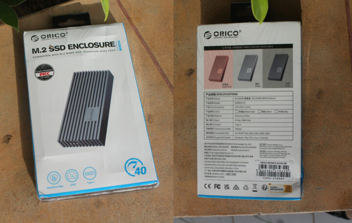
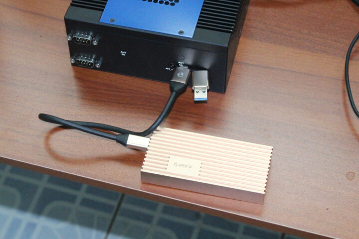
The exact model I received is the ORICO M234C3-U4 with a Rose Gold aluminum enclosure (107x50x17mm), supporting M.2 M-Key and B+M Key 2230, 2242, 2260, 2280 SSDs (more on that later), and offering up to 40 Gbps through its USB 4.0 port.
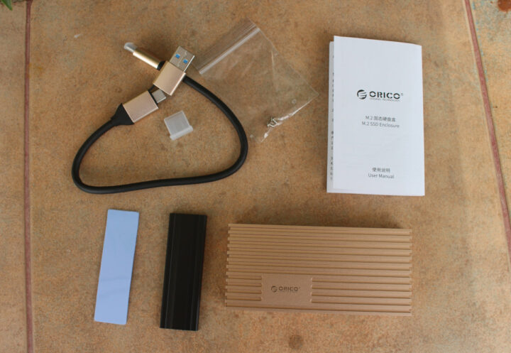
The device ships with a USB Type-C to USB Type-C/Type-A cable, a thermal pad, a heatsink, two screws, and a multilingual user manual.
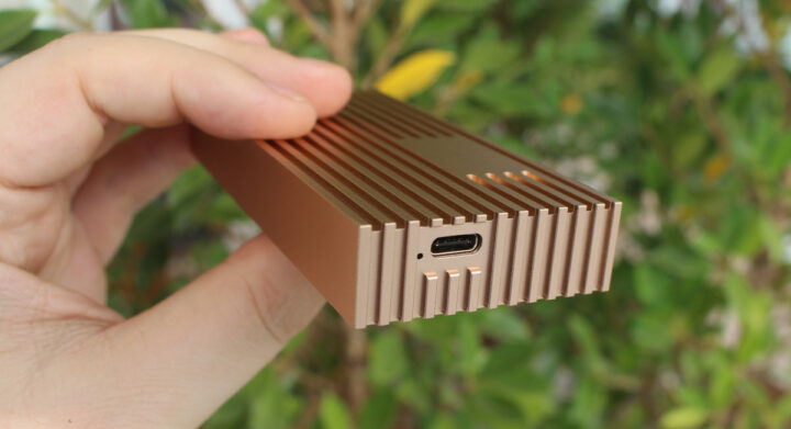
There’s only one USB Type-C port one the device.
M.2 NVMe SSD installation
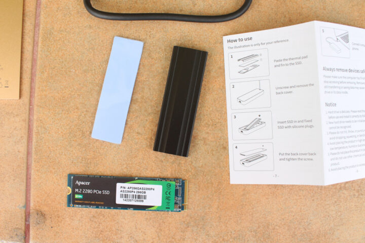
I’ll be using a 256GB Apacer M.2 2280 PCIe Gen3 x4 SSD (AS2280P4) that’s supposed to support 1,800 MB/s read speeds and 1,100 MB/s write speed. 1,800MB/s corresponds to about 14.4 Gbps. That’s not quite close to 40 Gbps, but still higher than the 10Gbps for USB 3.1 Gen 2 ports, so we’ll see if we can reach anything close to those speeds.
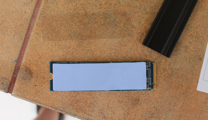
My SSD comes with a sticker, and I suppose it should be better to remove it before installing the thermal pad for even better cooling. The only problem is that it serves as a warranty sticker too (See “Warranty void is label removed” at the bottom left corner). So I’ve kept it. Just remember to remove the plastic films before putting the thermal pad on the SSD.
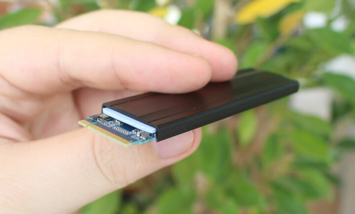
The next step is to clip the heatsink on top of the thermal pad.
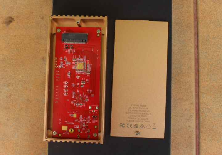
We know need to open the enclosure secured with a single screw.
While the specifications mention support for M.2 2230, 2242, 2260, and 2280 SSDs, there are no mounting holes for the smaller size, so getting an M.2 2280 NVMe SSD is the only practical choice.
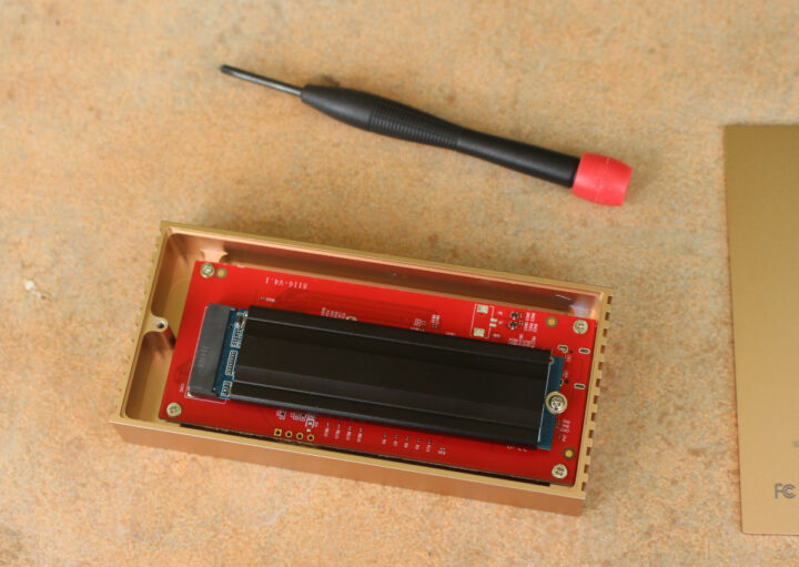
We can now insert the SSD in the enclosure, secure it with one of the provided crews, before putting the cover back in place.
ORICO USB 4.0 M.2 SSD enclosure in Ubuntu 20.04
Here’s the USB 4.0 enclosure connected to the USB 4.0 Type-C port of UP Xtreme i11 mini PC running Ubuntu 20.04. The metal enclosure is quite hot to the touch even at idle, but that’s a good sign meaning it’s cooling the SSD.
There’s a fairly long output in the kernel log once I insert the device, but it ends with:
|
1 2 3 4 5 6 7 8 9 10 11 12 13 14 15 16 17 18 19 |
[19177.462958] usb usb5: New USB device found, idVendor=1d6b, idProduct=0002, bcdDevice= 5.13 [19177.462960] usb usb5: New USB device strings: Mfr=3, Product=2, SerialNumber=1 [19177.462961] usb usb5: Product: xHCI Host Controller [19177.462963] usb usb5: Manufacturer: Linux 5.13.0-48-generic xhci-hcd [19177.462964] usb usb5: SerialNumber: 0000:17:00.0 [19177.463074] hub 5-0:1.0: USB hub found [19177.463084] hub 5-0:1.0: 2 ports detected [19177.463190] usb usb6: New USB device found, idVendor=1d6b, idProduct=0003, bcdDevice= 5.13 [19177.463192] usb usb6: New USB device strings: Mfr=3, Product=2, SerialNumber=1 [19177.463193] usb usb6: Product: xHCI Host Controller [19177.463194] usb usb6: Manufacturer: Linux 5.13.0-48-generic xhci-hcd [19177.463196] usb usb6: SerialNumber: 0000:17:00.0 [19177.463278] hub 6-0:1.0: USB hub found [19177.463286] hub 6-0:1.0: 2 ports detected [19177.473185] nvme nvme0: missing or invalid SUBNQN field. [19178.773047] nvme nvme0: allocated 64 MiB host memory buffer. [19178.784324] nvme nvme0: 8/0/0 default/read/poll queues [19184.657901] thunderbolt 0-1: new device found, vendor=0x8086 device=0x12 [19184.657909] thunderbolt 0-1: Intel USB4.0 SSD |
There are two new USB hubs (Bus 0006 and 005) and an Intel USB4.0 SSD which looks good, but those are USB 3.0 and USB 2.0 root hubs.
|
1 2 3 4 5 6 7 8 |
$ lsusb Bus 004 Device 001: ID 1d6b:0003 Linux Foundation 3.0 root hub Bus 003 Device 002: ID 1934:1202 Feature Integration Technology Inc. (Fintek) Fintek U2U F81532 AA66 Bus 003 Device 001: ID 1d6b:0002 Linux Foundation 2.0 root hub Bus 002 Device 001: ID 1d6b:0003 Linux Foundation 3.0 root hub Bus 001 Device 001: ID 1d6b:0002 Linux Foundation 2.0 root hub Bus 006 Device 001: ID 1d6b:0003 Linux Foundation 3.0 root hub Bus 005 Device 001: ID 1d6b:0002 Linux Foundation 2.0 root hub |
and indeed when I look at the data with lsusb, there’s no USB 4.0 port, nor anything at 40000M:
|
1 2 3 4 5 6 7 8 |
$ sudo lsusb -t /: Bus 06.Port 1: Dev 1, Class=root_hub, Driver=xhci_hcd/2p, 10000M /: Bus 05.Port 1: Dev 1, Class=root_hub, Driver=xhci_hcd/2p, 480M /: Bus 04.Port 1: Dev 1, Class=root_hub, Driver=xhci_hcd/4p, 10000M /: Bus 03.Port 1: Dev 1, Class=root_hub, Driver=xhci_hcd/12p, 480M |__ Port 9: Dev 2, If 0, Class=Vendor Specific Class, Driver=f81534, 480M /: Bus 02.Port 1: Dev 1, Class=root_hub, Driver=xhci_hcd/4p, 10000M /: Bus 01.Port 1: Dev 1, Class=root_hub, Driver=xhci_hcd/1p, 480M |
That’s odd. So we probably need to check with thunderbolt/usb4.0 specific tools:
|
1 |
sudo apt install thunderbolt-tools |
Now I can get more information:
|
1 2 3 4 5 6 7 8 9 10 11 12 13 14 15 |
$ tbtadm devices 0-1 Intel USB4.0 SSD authorized not in ACL $ tbtadm topology Controller 0 ├─ Details: │ ├─ Name: Unknown device, Unknown vendor │ └─ Security level: SL0 (none) │ └─ USB4.0 SSD, Intel └─ Details: ├─ Route-string: 0-1 ├─ Authorized: Yes ├─ In ACL: No └─ UUID: 00166a50-7dc4-8680-ffff-ffffffffffff |
But that does not show anything about speed, just that a Thunderbolt device is detected. (Check out the comments section for more information about that). The SSD drive is also properly detected:
|
1 2 3 4 5 |
$ inxi -D Drives: Local Storage: total: 357.72 GiB used: 49.11 GiB (13.7%) ID-1: /dev/nvme0n1 vendor: Apacer model: AS2280P4 256GB size: 238.47 GiB ID-2: /dev/sda vendor: Transcend model: TS128GSSD452K2 size: 119.24 GiB |
… although not mounted, so I used pmount after modifying /etc/pmount.allow file to resolve the error “device /dev/nvme0n1 is not removable”.
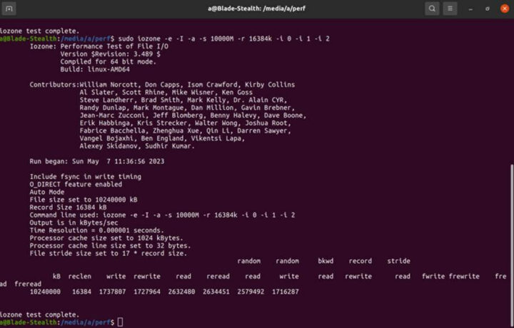
Let’s see what kind of performance we have with iozone:
|
1 2 3 4 5 6 7 8 9 |
devkit@UPX-i11:/media/nvme0n1$ sudo iozone -e -I -a -s 10000M -r 16384k -i 0 -i 1 -i 2 Iozone: Performance Test of File I/O Version $Revision: 3.489 $ Compiled for 64 bit mode. Build: linux-AMD64 random random bkwd record stride kB reclen write rewrite read reread read write read rewrite read fwrite frewrite fread freread 10240000 16384 1115937 1114626 1155245 1154974 1155950 1115576 |
I repeated the benchmark three times with about the same results each time. All results, namely sequential write/read and random read/write, are about in the same range of about 1100 MB/s which may indicate some issue. That number is also close to 10 Gbps, so we may indeed have a USB connection limited to 10 Gbps as reported by lsusb -t command.
For comparison, I’ve also run the fio command used by Hardkernel to test ODROID-M1‘s NVME SSD performance:
|
1 2 |
devkit@UPX-i11:/media/nvme0n1$ sudo fio --filename=/dev/nvme0n1 --direct=1 --rw=read --bs=1024k --ioengine=libaio --iodepth=64 --size=4G --runtime=10 --numjobs=4 --group_reporting --name=fio-rand-read-sequential --eta-newline=1 --readonly | grep READ READ: bw=1204MiB/s (1263MB/s), 1204MiB/s-1204MiB/s (1263MB/s-1263MB/s), io=12.2GiB (13.2GB), run=10417-10417msec |
1,263MB/s is about 12% higher than the 1,128MB/s read speed found with iozone, but still far from the 1800MB/s advertised for the SSD, and 1,263 MB/s happens to be 10104 Mbps.
It looks like UP Xtreme i11 may be the bottleneck here as the usb4.0 port is advertised as having “usb3.10” capabilities with a maximum speed of 10000Mbit/s:
|
1 2 3 4 5 6 7 8 9 10 11 |
$ sudo lshw | grep -A10 -i usb .... -usbhost:1 product: xHCI Host Controller vendor: Linux 5.13.0-48-generic xhci-hcd physical id: 1 bus info: usb@4 logical name: usb4 version: 5.13 capabilities: usb-3.10 configuration: driver=hub slots=4 speed=10000Mbit/s |
If I understand that correctly that’s normal we are limited to 10 Gbps speed. I’ll double-check with AAEON to make sure.
[Update: AAEON has purchased a similar ORICO M.2 SSD Thunderbolt enclosure (ORICO-M2V02-C4) and tested it on their side with UP Xtreme i11 and a Samsung MZ-V8V500 SSD with the iozone utility.
That’s a sequential/random write speed of up to 1700MB/s (13.6Gbps), and a sequential/random read speed of up to 2600MB/s (20.8Gbps), so both data transfer rates are over 10Gbps showcasing that the USB4 port can offer up to 20Gbps transfer speeds, double what USB 3.1 Gen2 can do.
]
A closer look at the board’s components
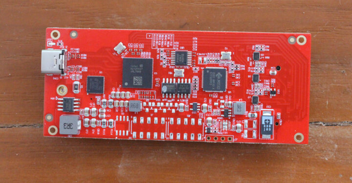
When I installed the SSD, I did not do a full teardown. So let’s do that now to find more details about the hardware.
We have a chip marked “Intel X212TC27 JHL7440” that’s an Intel JHL7440 Thunderbolt 3 controller that should be capable of 40 Gbps speed and a JMS583 chip that sounds familiar as the “USB 3.1 Gen 2 to PCIe NVMe Gen3 x2” has been found in several products covered in CNX Software over the years… I initially found it quite odd to have a 10 Gbps chip in a 40 Gbps device, but that’s for backward compatibility, and if I connect the driver to the USB 3.0 port from my laptop, the JMS583 chip is used instead (See comments for details).
The “USB 4.0” 40Gbps model reviewed here costs $169.99 on Amazon, while the price for the 20Gbps model drops to $54.99, and the 10 Gbps model sells for just $29.99. So if you purchase this item on Amazon, double-check your USB 4.0 / Thunderbolt port does indeed support 40 Gbps, as well as your drive speed in order to avoid overpaying. [Update: an industry insider working on USB4 has confirmed this enclosure has nothing to do with USB4, and it’s just an enclosure combining Thunderbolt 3 with a fallback to USB 3.2 Gen 1]

Jean-Luc started CNX Software in 2010 as a part-time endeavor, before quitting his job as a software engineering manager, and starting to write daily news, and reviews full time later in 2011.
Support CNX Software! Donate via cryptocurrencies, become a Patron on Patreon, or purchase goods on Amazon or Aliexpress. We also use affiliate links in articles to earn commissions if you make a purchase after clicking on those links.




Could you please check to see if this SSD enclosure support fstrim in ubuntu? Otherwise it would be pretty useless in the long (and not so long?!) run. THANKS!
I can run the following command without errors:
Thanks! I assume it also supports SMART? (forgot to ask)
Somewhat related suggestio/plead: It would be huge public service if could you do a review of popular and/or budget-oriented external ssd and/or ssd enclosure and see which ones support fstrim/smart in linux. It is incredibly difficult to find this information, and often the only way to find out is to have one in your hand and then test it to learn that it does not work (don’t ask me how I know!). THANKS!
That’s actually something I wanted to do during the review, but I forgot:
> see which ones support fstrim/smart in linux
Jean-Luc is accessing this thing as /dev/nvme0n1 so no USB involved at all (it’s NVMe being transported over PCIe over Thunderbolt) and as such no problems wrt TRIM/SMART.
To test the JMS583 (one of these brain-damaged USB-to-NVMe bridges) the provided USB-C-to-A adapter might be sufficient to hide Thunderbolt/PCIe from the host.
Fortunately, we don’t have to theorize as Jean-Luc checked for you, but this isn’t a USB to NVME adapter, but a thunderbolt one, so it’s actually on a PCI-E connection all the way through. A non-TB enclosure would be PCI-E(inside the computer) to USB (port on computer) via a cable to USB (port on the enclosure) converted to NVME (connection to the M.2 drive. With TB, all the same connections exist, but they’re not doing a USB protocol like mass storage or UASP, they’re tunneling the acutal PCI-E connection over the USB cable.
Which I think may be important here. This SSD appears to be a DRAM-less model which means it likely needs a small chunk of host memory to store important data in. That data transfer would have to go over the TB ‘tunnel’ and I’m very curious how that extra latency effects drive performance. If the link is actually running at 10Gb/s as it seems to be, that will quadruple the data transfer portion of the latency over what it would be at 40Gb/s. We do need to keep in mind that the PCI-E v3.0 x4 link has a BW of 32Gb/s. All of these figures are raw wire rates and don’t account for all of the protocol and encoding overhead, so you’ll never see such rates on actual transfers.
> they’re tunneling the acutal PCI-E connection over the USB cable.
Well, it needs to be a Thunderbolt cable, doesn’t it? Or at least an ‘USB 4.0 cable’ since this implies Thunderbolt capabilities…
Technically most quality 20 Gbps USB-C cables can do 40 Gbps, as long as they’re not over a metre in length.
Has anybody tested the speed of the Thunderbolt 4 interface in Tiger Lake computers? I can’t find any data only press releases and announcements claiming 40 Gbps.
Have you already checked link width/speed via lspci -v? And while benchmarking the storage watched CPU utilization via atop/htop?
Here’s the part related to Thunderbolt 3:
Sorry, there was a -v missing. The SSD itself should be listed and tell which PCIe capabilities have been negotiated (there’s link training and such stuff also over Thunderbolt).
Output from the command:
I guess it’s not what we need… So here’s the full output from lspci -vv
I suppose that’s the relevant bit:
That should be the speed for PCIe Gen3 x4.
> there’s no USB 4.0 port
Since such thing doesn’t exist. USB 4.0 is a protocol revision (formerly known as ‘Thunderbolt 3’ – at least USB 4 is TB3 with some minor changes) and 40 Gbps are only possible using Thunderbolt and not USB. But even then a host calling itself ‘USB 4.0 compliant’ only needs to support TB3 at 20 Gbps (and USB at 10 Gbps).
Have you tried to install the bolt package and used boltctl to get some more details?
boltctl was already installed. Here’s the output:
That’s not true though, as there’s a USB4 data standard as well. USB4 is compatible with Thunderbolt 3, although in this case, it appears to be a Thunderbolt 3 controller with a USB 3.2 fallback solution that’s being sold as USB4, which this device clearly isn’t.
Thunderbolt 3 can only do 32 Gbps of data, whereas USB4 can do 40 Gbps. You are correct that 20 Gbps is “good enough” though.
The 10 Gbps fallback mode is only for USB 3.2 mode, not for USB4, which has to be at least 20 Gbps.
Oh and technically a USB4 peripheral only needs to support legacy USB and tunneled USB 3.2 data at 10 Gbps to be certified as a USB4 for device…
The most feature stringent devices are hubs for some reason, followed by hosts then devices. Hosts don’t even have to support PCIe/Thunderbolt 3.
Wikipedia has some pretty solid info now that you might want to check to do a refresher.
That’s Intel’s reply
https://camo.githubusercontent.com/3ca6e9600a38969dc56b1e38d5acc25d95e1ddcbe59a62408fd0a0fb69081f58/68747470733a2f2f68656973652e636c6f7564696d672e696f2f77696474682f333039322f7137302e706e672d6c6f7373792d37302e776562702d6c6f7373792d37302e666f696c312f5f7777772d68656973652d64655f2f696d67732f31382f332f302f302f312f352f362f382f7468756e646572626f6c74342d636f6d70617269736f6e2d63686172742d326630616165396336643865303864372e6a7067
Well, you’re missing the context and the features depend on the type of device. I really suggest you check Wikipedia or read my primer over on TechPowerUp, as I went and talked to actual USB4 host and device manufacturers.
If I connect it to my laptop (USB 3.0 Type-A) port it indeed goes through the JMS583 chip, and shows up as /dev/sdc instead:
“The metal enclosure is quite hot to the touch even at idle”
I was under the impression (perhaps in error) that M,2 SSDs ran fairly cool.
Is the heat in fact being generated by the USB/Thunderbolt electronic components of the enclosure rather than the SSD its-self?
Are you able to get a temperature value from the SSD using hddtemp or perhape, more probably, smartctl -a? [ “a” for all attributes rather than just “i” for identity info]
Just about 15 minutes after booting the mini PC:
48C. The enclosure is not quite that hot to the touch yet.
Thanks for getting the data. It is certainly warmer than I expected.
By comparison, for a traditional SSD 960 GB in 2.5 inch format
hddtemp /dev/sda
/dev/sda: PNY CS900 960GB SSD: 33°C
(The hddtemp utility in fact gets the data from the SMART capability of the disk and it can be run in daemon mode for serving data on a TCP port which can be used by another daemon process to grab the temperature values and store them in an RRD for later processing and displaying as a graph.)
> It is certainly warmer than I expected
You might think about why M.2 SSD heatsinks with 15mm height exist 😉
> grab the temperature values and store them in an RRD
I’ve not seen any SATA SSD so far that doesn’t do this on its own. smartctl -l scttemp /dev/sd? will show the drive’s thermal history 🙂 With NVMe it’s a different story. At least nvme smart-log /dev/nvme? will show when tresholds have been exceeded.
Does this also offer PCIe in the M.2 slot and if so do you think that this could be used with a Intel Wi-Fi 6E AX210 M.2 2230 board if use an A+E to M-key adapter for WiFi cards as it support standard Key A or Key E socket for attaching the WiFi module?
Reason I ask is that there are still no WiFi 6E USB adapters
available so currious if this could be converted into one.
PCIe is there since it’s for NVMe (PCIe) drives, but I don’t know if WiFi cards would be supported. You’d also need to drill the metal enclosure for the antenna(s).
I have issues with the JMS583 controller of this Orico M234 enclosure. After switching/replacing the mounted SSD from a Seagate FireCuda 530 to a Samsung 970 Evo, I can’t go back to the FireCuda 530 anymore. The JMS583 controller is stuck with reporting the Samsung 970 EVO is mounted.
Even if no SSD is installed at all, the JMS583 controller still claims/reports to the OS the Samsung 970 is present (see dmesg output below).
The Thunderbolt Controller (JHL744) doesn’t have this issue and correctly recognizes when you switch/replace the mounted SSD.
So I’m stuck in a state, where I can use the enclosure via USB (JMS583) only with the mounted Samsung 970 EVO – and then it works fine – but with no other SSD installed.
Is there any known way to “reset” the JMS583 controller? Simple unplugging/powering (Power-off -> Power-On) multiple times in a row doesn’t fix it. Or what about Firmware Upgrades? I don’t find any official Support Website for this enclosure.
usb 4-2: USB disconnect, device number 12usb 4-2: new SuperSpeed Gen 1 USB device number 13 using xhci_hcd
usb 4-2: New USB device found, idVendor=152d, idProduct=0584, bcdDevice= 2.12
usb 4-2: New USB device strings: Mfr=1, Product=2, SerialNumber=3
usb 4-2: Product: JMS583
usb 4-2: Manufacturer: JMicron
usb 4-2: SerialNumber: DD56419883EE8
scsi host1: uas
scsi 1:0:0:0: Direct-Access Samsung SSD 970 EVO 0212 PQ: 0 ANSI: 6
sd 1:0:0:0: Attached scsi generic sg1 type 0
sd 1:0:0:0: [sda] Unit Not Ready
sd 1:0:0:0: [sda] Sense Key : Hardware Error [current]
sd 1:0:0:0: [sda] ASC=0x44 <<vendor>>ASCQ=0x81
sd 1:0:0:0: [sda] Read Capacity(16) failed: Result: hostbyte=DID_OK driverbyte=DRIVER_SENSE
sd 1:0:0:0: [sda] Sense Key : Hardware Error [current]
sd 1:0:0:0: [sda] ASC=0x44 <<vendor>>ASCQ=0x81
sd 1:0:0:0: [sda] Read Capacity(10) failed: Result: hostbyte=DID_OK driverbyte=DRIVER_SENSE
sd 1:0:0:0: [sda] Sense Key : Hardware Error [current]
sd 1:0:0:0: [sda] ASC=0x44 <<vendor>>ASCQ=0x81
sd 1:0:0:0: tag#24 uas_eh_abort_handler 0 uas-tag 1 inflight: IN
sd 1:0:0:0: tag#24 CDB: Inquiry 12 01 00 00 40 00
scsi host1: uas_eh_device_reset_handler start
usb 4-2: reset SuperSpeed Gen 1 USB device number 13 using xhci_hcd
scsi host1: uas_eh_device_reset_handler success
sd 1:0:0:0: [sda] 0 512-byte logical blocks: (0 B/0 B)
sd 1:0:0:0: [sda] 0-byte physical blocks
sd 1:0:0:0: [sda] Test WP failed, assume Write Enabled
sd 1:0:0:0: [sda] Asking for cache data failed
sd 1:0:0:0: [sda] Assuming drive cache: write through
sd 1:0:0:0: [sda] Optimal transfer size 33553920 bytes not a multiple of physical block size (0 bytes)
sd 1:0:0:0: [sda] Unit Not Ready
sd 1:0:0:0: [sda] Sense Key : Hardware Error [current]
sd 1:0:0:0: [sda] ASC=0x44 <<vendor>>ASCQ=0x81
sd 1:0:0:0: [sda] Read Capacity(16) failed: Result: hostbyte=DID_OK driverbyte=DRIVER_SENSE
sd 1:0:0:0: [sda] Sense Key : Hardware Error [current]
sd 1:0:0:0: [sda] ASC=0x44 <<vendor>>ASCQ=0x81
sd 1:0:0:0: [sda] Read Capacity(10) failed: Result: hostbyte=DID_OK driverbyte=DRIVER_SENSE
sd 1:0:0:0: [sda] Sense Key : Hardware Error [current]
sd 1:0:0:0: [sda] ASC=0x44 <<vendor>>ASCQ=0x81
I received a response from ORICO Support:
That’s insane! Isn’t there any factory reset? Apparently not…
Late to the game here. I have a Minis Forum UM690 (Ryzen 9 6900HX) which has a C port labeled “USB4” on the front. It uses the AMD USB4 controller and its really a protocol switch/router depending on what is plugged into the port. I plugged in several devices like a TB3 dock, and USB-C dock and finally a USB 3.2 Gen 2 flash drive (SanDisk Extreme Pro). lspci shows the AMD USB4 switch as a 16GT/s PCI Gen 4 with a x16 width interface. According to the PCI Forum that should provide a maximum of 31.5GBps of throughput.
Using lsusb won’t show it because the AMD switch is not a hub or an XHCI controller, at least not until something is plugged in to it. The other oddity is when I plug in a Thunderbolt 3 device, the AMD switch exposes the TB devices to the kernel for detection (and the thunderbolt kernel module loads) but none of the TBT tools will work because the AMD switch is not exposing it as a traditional TB hub, only the actual devices. And they work just fine.
This has been throwing people off on what exactly this port is doing.
If you plug in a flash drive, the switch sets up a virtual USB hub (usually an XHCI/USB3.1 type) and it is immediately detected by the host OS as a traditional USB device insertion. At this time lsusb detects that a device is there and extracts all of its connection metadata.
I was able to get just under 8Gbps for both read and write with the USB 3.2 Gen 2 flash drive which is not the full 10Gbps documented under the specification, but obviously much faster than the 5Gbps of the Gen 1 specification.