
The product we are reviewing today is the “MaTouch ESP32-S3 Rotary IPS Display with Touch 2.1” ST7701″ from Makerfabs which offers an alternative to the MaTouch_ESP32-S3 4-inch Display Demo Kit that we reviewed a few months ago.
Just like the earlier model, the new kit is equipped with an ESP32-S3-WROOM-1-N16R8, featuring 16MB of flash memory and 8MB of PSRAM. This device supports both Wi-Fi and Bluetooth 5.0 wireless communication and offers connectivity options through I2C and UART ports for interfacing with external devices. The display features a round IPS panel with a resolution of 480×480 pixels, capacitive touch capability, and LVGL library support. Additionally, it includes a mechanical rotary encoder and supports press operations.
MaTouch ESP32-S3 Rotary IPS Display specifications
- Controller: ESP32-S3-WROOM-1, PCB Antenna, 16MB Flash, 8MB PSRAM, ESP32-S3-WROOM-1-N16R8
- Wireless: Wi-Fi and Bluetooth 5.0
- LCD: 2.1-inch High Lightness IPS,65K color
- LCD Driver: ST7701S
- FPS: > 70
- Resolution: 480×480
- LCD interface: RGB 565
- Touch Panel: 5 Points Touch, Capacitive
- Touch Panel Driver: CST8266
- USB: USB Type-C native
- Expansion: 1x I2C; 1x UART (1.25mm 4-pin connector)
- Arduino support: Yes
- Operation temperature: -40°C to +85°C

Unboxing
The display is packaged within a cardboard box and includes the following items:
- 1x MaTouch ESP32-S3 Rotary IPS Display with Touch 2.1” ST7701
- 1x 1-meter USB Type-C cable
- 2x wires with 1.25mm 4-pin connector


Checking out the default firmware
This MaTouch ESP32-S3 Rotary IPS Display kit comes with pre-installed demo firmware. You can power the module using a 5V USB Type-C connection. The default screen displays values from the rotary encoder, the status of the push switch, and the (x, y) coordinates of the touch point. When you rotate the rotary encoder, the background color alternates between 5 colors, namely white, blue, green, red, and green.

If you press the button, the screen will be switched to the graphic modes as shown below. There are 3 examples of graphic modes and you can switch between them by touching the center of the screen. In this mode, a gauge is shown and you can rotate the rotary encoder to adjust the position of the indicator, or you can touch and drag your finger to change the value too.


Software Installation
I’m going to use Arduino IDE for the demonstrations. So we’ll need to install support for the board (through the board manager) and install all of the required libraries. I summarize them as follows.
- Install the Arduino IDE. The manufacturer suggests us to use Arduino IDE 1.8.10/1.8.19
- Install the ESP32 Board Package, the 2.0.6 version is suggested.
- Install GFX Library for Arduino 1.3.1
- Download the source from this GitHub and extract it. Then, copy the ui folder from /example/squareline_demon/libraries/ui to the Arduino’s library folder. However, For this review, I’m going to use the ui library from /example/test_fw_v2/library/ui because it offers more variables and functions than those in the suggested folder. Also, we have to extract the mf_lvgl and TouchLib from /lib/mf_Lvgl.zip and /lib/TouchLib.zip to the Arduino’s library too.
- Select “ESP32S3 Dev Module” board and set other settings as in the following figure.

In the following tests, I will be using Arduino IDE 1.8.13 to demonstrate the device through 4 examples. I’ll begin with a simple demonstration, focusing on the rotary encoder and push switch. Then, we’ll explore changing the background color by touching the screen. Next, I’ll demonstrate how to change the background bitmap. Finally, I’ll read data from an accelerometer via the I2C port to adjust the background color.
TEST-1: Using the Rotary Encoder and the Switch Button
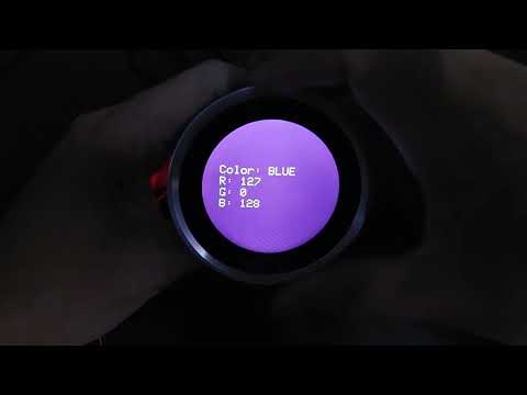
In our first example, we’ve extended the default firmware page. Here, we use the push switch to switch the background color between red, green, and blue colors. Rotating the rotary encoder allows us to adjust the intensity of the selected color, and we also take into account the rotation direction. If the encoder is rotated counterclockwise (CCW), the intensity decreases, while it increases if rotated in the opposite direction (CW).
To achieve this, we’ve used the source code from /example/fw_test and introduced several constants and variables for the above purposes.
|
1 2 3 4 5 6 7 8 |
#define MY_COLOR_MODE_R 0 #define MY_COLOR_MODE_G 1 #define MY_COLOR_MODE_B 2 #define MY_COLOR_ADJUST_STEP 16 int color_mode = MY_COLOR_MODE_R; uint8_t color_values[3] = {0, 0, 0}; int encoder_value_prev = 0; int encoder_value_current = 0; |
We then modified the update_color_values() function to compare the current rotary encoder value with the previous one in order to determine the direction of the rotation. After that, we apply the constant value, defined in MY_COLOR_ADJUST_STEP, to adjust the intensity of the selected color value according to the rotation direction.
|
1 2 3 4 5 6 7 8 9 10 11 12 13 14 15 16 17 18 19 20 21 22 23 24 25 26 27 28 29 30 31 |
void update_color_values() { int delta = 0; encoder_value_current = counter; delta = encoder_value_current - encoder_value_prev; if(abs(delta) < 2) { return; } if(delta > 0) { // Update the value color_values[color_mode] += MY_COLOR_ADJUST_STEP; } else { color_values[color_mode] -= MY_COLOR_ADJUST_STEP; } encoder_value_prev = encoder_value_current; // limit the min/max if(color_values[color_mode] > 255) { color_values[color_mode] = 255; } if(color_values[color_mode] < 0) { color_values[color_mode] = 0; } } |
Within the main loop, we first check if the variable move_flag is set. If it is, we call the above update_color_values() function to update our color values. Then, the updated RGB color values are packed into a single uint16_t data type by using the color565 method of the Arduino_ST7701_RGBPanel class. We subsequently pass the converted value to the fillScreen method to change the background color. Once the script is compiled and uploaded, you’ll see a screen similar to what is demonstrated in the following video.
TEST-2 : Using the Touch Screen
Our next test is inspired by the HSV color model where the color value for each position on the screen is determined by its (x, y) coordinates relative to the center of the screen, as shown in the following figure. For this example, we are keeping the saturation (S) and value (V) fixed at their maximum values and will only change the hue (H).

To calculate the RGB values, we first shift the origin of the coordinate system to the center of the screen. We then calculate the angle t in the above figure using the formula: t = atan2(dy, dx). With this angle, we determine the RGB color values through the following calculation where t2 represents the separation angle between each color value, which is equal to 120 degrees or (2*pi)/3 radians.
|
1 2 3 |
R = 255 * ((cos(t )/2.0) + 0.5); G = 255 * ((cos(t+t2)/2.0) + 0.5); B = 255 * ((cos(t–t2)/2.0) + 0.5); |
Additionally, we calculate the distance from the touch point to the center of the screen. This distance is then used to adjust the brightness of the background color.
|
1 2 3 4 5 6 7 8 9 10 11 12 13 14 15 16 17 18 19 20 21 22 23 24 25 26 27 28 29 30 31 32 33 34 35 36 37 38 39 40 |
void update_color_values() { ... // Shift origin to center of the screen int dx = x - 240; int dy = 240 - y; // angle float angle = atan2(dy, dx); // distance float dist = sqrt((dx*dx) + (dy*dy)); float v = dist/240.0; // Hue float t = angle; float t_step = 120.0 * DEG_TO_RAD; float r = 255 * ((cos(t )/2.0) + 0.5); float g = 255 * ((cos(t + t_step)/2.0) + 0.5); float b = 255 * ((cos(t - t_step)/2.0) + 0.5); // Adjust brightness r = v * r; g = v * g; b = v * b; // Limit the min/max if(r > 255.0) { r = 255.0; } if(g > 255.0) { g = 255.0; } if(b > 255.0) { b = 255.0; } if(r < 0.0) { r = 0.0; } if(g < 0.0) { g = 0.0; } if(b < 0.0) { b = 0.0; } // Update the values color_values[0] = (uint8_t)r; color_values[1] = (uint8_t)g; color_values[2] = (uint8_t)b; ... } |
After uploading the script, you’ll observe something similar to the video below.

TEST-3 : Using the Light and Versatile Graphics Library (LVGL)
Next, we will use the Light and Versatile Graphics Library (LVGL). In this test, we will use the source code from the /example/fw_test_v2 and attempt to change the background image with our custom bitmap.
So, the first step is to create a 480×480 bitmap and export it as a 32-bit PNG with the filename “1.png“. Then, we convert this PNG image to C-style data using the SquareLine Studio software. In the software, we set the bit depth to 16-bit, as shown in the figure below. After setting the output path and exporting the project, we will obtain a source file named “ui_img_1_png.c“. This is our final custom bitmap that can be used to replace the original file in the src/images folder.

As an additional option, you can also experiment with adjusting the colors of other UI elements manually within the source file ui_Screen3.c. The figure below provides an example of the modified ui_Screen3.c source file where we have made alterations to the background color, opacity, and the color of the indicator.


TEST-4 : Using the I2C Connection
In our last demonstration, we will test communication with another device using the I2C protocol. For this test, we connect the MPU-6050 module to our module using the 1.25mm 4P connector as shown below.
- RED: GND → MPU6050 GND
- GREEN: +3V3 → MPU6050 VIN
- BLUE: SDA → MPU6050 SDA
- YELLOW: SCL → MPU6050 SCL


y = 255 * ((x – min) / range)), where x represents the input value, while min and range are the minimum and range of the values for each axis. For this test, we’ve simply set the minimum values for all axes to -9,000 and the range of all axes to 18,000. After scaling, the acceleration values will fall within the range [0, 255], which can then be employed as the intensity for the RGB color. Therefore, we are utilizing the acceleration data from the x-axis, y-axis, and z-axis to control the intensity of the red, green, and blue colors, respectively.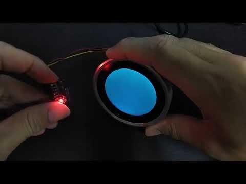
Conclusions
In summary, the “MaTouch ESP32-S3 Rotary IPS Display with Touch 2.1” ST7701” is easy to use and features a vibrant color display. The manufacturer provides clear installation instructions for tool installations. I would like to express my sincere appreciation to MakerFabs for providing the device used in this review. Lastly, if you have an interest in this module, you can make a purchase through MakerFabs’ online store, where it is currently available for $44.80.

My main research areas are digital image/audio processing, digital photogrammetry, AI, IoT, and UAV. I am open to other subjects as well.
Support CNX Software! Donate via cryptocurrencies, become a Patron on Patreon, or purchase goods on Amazon or Aliexpress. We also use affiliate links in articles to earn commissions if you make a purchase after clicking on those links.


Looks good. Is there any control over the stepper motor response, like adding custom detents at a single or multiple points?
I would LOVE to see one of these with 3 inch screen and a 3 3/8 inch body so it would fit nicely in some gauge clusters!
Another great article/review, an interesting device for sure.
Can you please post the full code examples? Modified examples do not appear to be correlated with the examples from the github repository or have at least changed significantly since this article was created.