
The Youyeetoo X1 x86 single board computer (SBC) with an Intel Celeron N5105 Jasper Lake CPU differs from a typical Intel or AMD mini PC by its range of IOs including SPI, I2C, UART, NFC connectivity, and support for PoE module that you won’t find in a typical computer, and that’s what we will test in the second part of the X1 SBC review along with power consumption.
The Youyeetoo X1 SBC is also different from Arm-based single board computers since we can just install any x86-compatible operating system by ourselves, and w don’t need to flash a board-specific image like we would do with Arm SBCs and peripherals such as SPI, I2C or UART may be or may not usable immediately due to lack of supported drivers.
We’ve already installed Ubuntu 22.04 on the Youyeetoo X1 in the first part of the review, so in the second part, we’ll use the instructions from the wiki to test the GPIOs and connect peripherals to the x86 SBC.
Configuring the GPIO voltage level on the Youyeetoo X1
The Youyeetoo X1 comes with several sets of GPIO JST connectors (2mm pitch) which can be used at 2 voltage levels: 1.8V and 3.3V. Configuring the voltage level involves updating the BIOS of the board, for example using the file “X1_01_Digital_S8_20231023175931_3.3V.bin” which can be decoded as being for the X1 board with 8GB RAM, digital microphone enabled, and the default MIPI 7 LCD screen with GPIO voltage of 3.3V. You can read more in the section to update the BIOS in the first part of the review.
Using GPIOs with libgpiod
We can use the GPIO User Space Subsystem & libgpiod to control the GPIOs on the board.
Let’s start by installing libgpiod and gpiod:
|
1 2 3 4 5 6 7 8 9 10 11 12 13 14 15 16 17 18 19 20 21 22 23 24 |
unoiot@unoiot-YouYeeToo-X1:~$ sudo apt -y install libgpiod-dev Reading package lists... Done Building dependency tree... Done Reading state information... Done libgpiod-dev is already the newest version (1.6.3-1build1). 0 upgraded, 0 newly installed, 0 to remove and 38 not upgraded. unoiot@unoiot-YouYeeToo-X1:~$ sudo apt -y install gpiod Reading package lists... Done Building dependency tree... Done Reading state information... Done The following NEW packages will be installed: gpiod 0 upgraded, 1 newly installed, 0 to remove and 38 not upgraded. Need to get 24.3 kB of archives. After this operation, 143 kB of additional disk space will be used. Get:1 http://th.archive.ubuntu.com/ubuntu jammy/universe amd64 gpiod amd64 1.6.3-1build1 [24.3 kB] Fetched 24.3 kB in 0s (151 kB/s) Selecting previously unselected package gpiod. (Reading database ... 226776 files and directories currently installed.) Preparing to unpack .../gpiod_1.6.3-1build1_amd64.deb ... Unpacking gpiod (1.6.3-1build1) ... Setting up gpiod (1.6.3-1build1) ... Processing triggers for man-db (2.10.2-1) ... |
Testing GPIOs with command line tools
We can now check the GPIO chip with the gpiodetect command. chip0 will be detected:
|
1 2 |
unoiot@unoiot-YouYeeToo-X1:~$ sudo gpiodetect gpiochip0 [INT34C8:00] (340 lines) |
The gpioinfo command allows us to check the status of each GPIO pin:
|
1 2 3 4 5 6 7 8 9 10 11 12 13 14 15 16 17 18 19 20 21 22 23 24 25 26 27 28 |
unoiot@unoiot-YouYeeToo-X1:~$ sudo gpioinfo 0 gpiochip0 - 340 lines: line 0: unnamed unused output active-high line 1: unnamed unused output active-high line 2: unnamed unused output active-high line 3: unnamed unused output active-high line 4: unnamed unused output active-high line 5: unnamed unused input active-high line 6: unnamed unused output active-high line 7: unnamed unused input active-high line 8: unnamed unused input active-high line 9: unnamed unused input active-high line 10: unnamed unused input active-high line 11: unnamed unused input active-high line 12: unnamed unused input active-high line 13: unnamed unused input active-high line 14: unnamed unused input active-high line 15: unnamed unused input active-high line 16: unnamed unused input active-high line 17: unnamed unused input active-high line 18: unnamed unused input active-high line 19: unnamed unused input active-high line 20: unnamed unused input active-high line 21: unnamed unused input active-high line 22: unnamed unused input active-high line 23: unnamed unused input active-high line 24: unnamed unused input active-high ... |
The get/set commands set the GPIO to input or output. If you use gpioset with a specific GPIO to change the flag to 0, the said GPIO will automatically be the output and if you use gpioget to read the state of the GPIO, it will automatically change the mode to input:
|
1 2 3 |
unoiot@unoiot-YouYeeToo-X1:~$ sudo gpioset 0 160=0 unoiot@unoiot-YouYeeToo-X1:~$ sudo gpioinfo 0 | grep "line 160" line 160: unnamed unused output active-high |
|
1 2 3 4 |
unoiot@unoiot-YouYeeToo-X1:~$ sudo gpioget 0 160 1 unoiot@unoiot-YouYeeToo-X1:~$ sudo gpioinfo 0 | grep "line 160" line 160: unnamed unused input active-high |
| Pin number | IO description | libgpiod control IO number |
|---|---|---|
| 1 | GPIO-H19 | 179 |
| 2 | GPIO-H18 | 178 |
| 3 | GPIO-H17 | 177 |
| 4 | GPIO-H16 | 176 |
| 5 | GPIO-H00 | 160 |
Subset of the GPIO pin to libgpiod number table
Python programming to control Youyeetoo X1 GPIO pins
It’s also possible to use Python to manage the GPIO, so we will install the python3-libgpiod as follows:
|
1 |
sudo apt install python3-libgpiod |
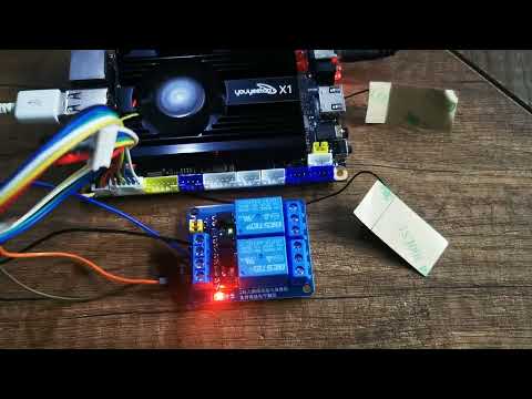
We will then do a quick test with the following program to blink an LED (or turn on and off a relay):
|
1 2 3 4 5 6 7 8 9 10 11 12 13 14 15 16 17 18 19 20 21 22 23 24 25 26 27 28 29 30 31 |
import gpiod, time # pins RELAY1 = 160 RELAY2 = 177 chip=gpiod.Chip('gpiochip0') relay1=chip.get_line(RELAY1) relay1.request(consumer="Relay1", type=gpiod.LINE_REQ_DIR_OUT) relay2=chip.get_line(RELAY2) relay2.request(consumer="Relay2", type=gpiod.LINE_REQ_DIR_OUT) def run(): delay = 1.0 try: while True: relay1.set_value(1) time.sleep(delay) relay1.set_value(0) time.sleep(delay) ''' duplicate relay2 here ''' finally: cleanup() def cleanup(): relay.release() if __name__ == "__main__": run() |
It’s all good as you can see from the video below.
Checking out I2C on Youyeetoo X1
I2C driver check
Let’s install i2c-tools to check if any I2C devices are detected.
|
1 |
sudo apt-get install i2c-tools |
After that, we can run the i2cdetect command to locate I2C devices. But before that, let’s have a look at the schematics that tell us I2C3 is accessible through a 4-pin connector.

So we have connected an I2C module with the ENS160 eCO2 sensor and the AHT21 temperature and humidity sensor using respectively 0x38 and x053 I2C addresses.

|
1 2 3 4 5 6 7 8 9 10 |
unoiot@unoiot-YouYeeToo-X1:~/linux-nfc/linux$ sudo i2cdetect -r -y 4 0 1 2 3 4 5 6 7 8 9 a b c d e f 00: -- -- -- -- -- -- -- -- 10: -- -- -- -- -- -- -- -- -- -- -- -- -- -- -- -- 20: -- -- -- -- -- -- -- -- -- -- -- -- -- -- -- -- 30: -- -- -- -- -- -- -- -- 38 -- -- -- -- -- -- -- 40: -- -- -- -- -- -- -- -- -- -- -- -- -- -- -- -- 50: -- -- -- 53 -- -- -- -- -- -- -- -- -- -- -- -- 60: -- -- -- -- -- -- -- -- -- -- -- -- -- -- -- -- 70: -- -- -- -- -- -- -- -- |
Again, it works fine with both sensors detected on the I2C bus.
Python program to test I2C
We will write a simple Python program to read values from I2C devices with the library smbus2 as follows:
|
1 2 3 4 5 6 7 8 9 10 11 12 13 14 15 16 17 18 19 20 21 22 23 24 25 26 27 28 29 30 31 32 33 34 35 36 37 38 39 40 41 42 43 44 45 46 47 48 49 50 51 52 53 54 55 56 57 58 |
from smbus2 import SMBus import time class AHT21: _i2cAddr = 0x38 def __init__(self): self.bus = SMBus(4) self._calibrate() def _write(self, data): self.bus.write_i2c_block_data(self._i2cAddr,0x0D , data) def _read(self, reg, len): return self.bus.read_i2c_block_data(self._i2cAddr, reg, len) def _calibrate(self): cal_cmd = [0xbe, 0x08, 0x00] self._write(cal_cmd) #todo delay perf counter?? need 50 us time.sleep(0.01) self._write([0x71]) # get status register res = self._read(self._i2cAddr, 1) if not res[0] & 0x68 == 0x08: print("Error calibrating.") return False else: print("Calibrating ok.") return True def Read(self): """Returns tuple (temp, humidity). Blocking delay at readout. """ read_cmd = [0xac, 0x33, 0x00] self._write(read_cmd) #todo delay perf counter?? need 80ms time.sleep(0.1) res = self._read(self._i2cAddr, 6) calc_hum = ((res[1] << 16) | (res[2] << 8) | res[3]) >> 4; calc_temp = ((res[3] & 0x0F) << 16) | (res[4] << 8) | res[5]; rh = calc_hum * 100 / 1048576; temp = calc_temp * 200 / 1048576 - 50; return (temp, rh) from AHT21 import AHT21 aht21 = AHT21() while True: result = aht21.Read() print("Relative Humidity : %.2f %%"%(result[1])) print("Temperature in Celsius : %.2f C"%(result[0])) print(" ************************************* ") time.sleep(1) |
The code above reads relative humidity and air temperature data from the AHT21 sensor and outputs those to the terminal.

That’s another pass.
Youyeetoo X1’s UART connectors
Checking whether the driver works
There are 3 sets of UARTs for us to use: UART1 to UART3, which are ttyS0, ttyS4 and ttyS5 as shown in a terminal window along with other interfaces:
|
1 2 3 4 |
unoiot@unoiot-YouYeeToo-X1:~$ sudo ls /dev/ttyS* /dev/ttyS0 /dev/ttyS11 /dev/ttyS14 /dev/ttyS17 /dev/ttyS2 /dev/ttyS22 /dev/ttyS25 /dev/ttyS28 /dev/ttyS30 /dev/ttyS5 /dev/ttyS8 /dev/ttyS1 /dev/ttyS12 /dev/ttyS15 /dev/ttyS18 /dev/ttyS20 /dev/ttyS23 /dev/ttyS26 /dev/ttyS29 /dev/ttyS31 /dev/ttyS6 /dev/ttyS9 /dev/ttyS10 /dev/ttyS13 /dev/ttyS16 /dev/ttyS19 /dev/ttyS21 /dev/ttyS24 /dev/ttyS27 /dev/ttyS3 /dev/ttyS4 /dev/ttyS7 |
We will be testing the UART2 interface available through the /dev/ttyS5 device with the following pinout.
| Pin Number | Description | Remarks |
|---|---|---|
| 1 | VCC | Output voltage 3.3V |
| 2 | TXD | Sending data TTL level |
| 3 | RXD | Receive data TTL level |
| 4 | GND | Power reference ground |
Testing UART with a with a GPS module

We will test UART by connecting the Beitian BN-180 GPS module based on the u-blox NEO-M8N module. Following the manufacturer’s instructions, we opened the screen program and set the /dev/ttyS5 port to 9600 bps baudrate:
|
1 |
sudo screen /dev/ttyS5 9600 |

We did receive some data, but to make it human-readable we installed the GPSD program.
|
1 2 3 4 5 6 7 8 9 10 11 |
unoiot@unoiot-YouYeeToo-X1:~$ sudo apt-get install gpsd Reading package lists... Done Building dependency tree... Done Reading state information... Done The following additional packages will be installed: gpsd-tools libgps28 Suggested packages: gpsd-clients The following NEW packages will be installed: gpsd gpsd-tools libgps28 0 upgraded, 3 newly installed, 0 to remove and 38 not upgraded. |
We also had to edit /etc/default/gpsd to start automatically and point to the UART2 port that the GPS module is connected to.
|
1 2 3 4 5 6 7 8 9 10 |
# Devices gpsd should collect to at boot time. START_DAEMON="true" # They need to be read/writeable, either by user gpsd or the group dialout. DEVICES="/dev/ttyS5" # Other options you want to pass to gpsd GPSD_OPTIONS="" # Automatically hot add/remove USB GPS devices via gpsdctl USBAUTO="true" |
The cgps program shows the correct GPS coordinates and other information as shown in the screenshot below.

NFC testing
The Youyeetoo X1 board is fitted with an ST25DV04K NFC chip that’s ready to use. You just need to install an NFC antenna which Youyeetoo happens to have for sale. An IPEX connector is used and the antenna can be connected to it as shown in the photo below.

We can test the NFC using a sample program provided by Youyeetoo that sends data (e.g. a URL) after the NFC antenna is tapped with a compatible smartphone.
|
1 2 3 4 5 6 7 8 9 10 11 12 13 |
unoiot@unoiot-YouYeeToo-X1:~$ wget http://d.youyeetoo.cn/X1/Linux-tools/linux-gpio-i2c-spi-nfc/nfc/linux-nfc-en.zip --2023-12-03 10:43:04-- http://d.youyeetoo.cn/X1/Linux-tools/linux-gpio-i2c-spi-nfc/nfc/linux-nfc-en.zip Resolving d.youyeetoo.cn (d.youyeetoo.cn)... 183.60.220.4, 183.60.220.9, 183.60.220.6 Connecting to d.youyeetoo.cn (d.youyeetoo.cn)|183.60.220.4|:80... connected. HTTP request sent, awaiting response... 200 OK Length: 3496000 (3.3M) [application/zip] Saving to: ‘linux-nfc-en.zip’ linux-nfc-en.zip 100%[=================================================================>] 3.33M 1.34MB/s in 2.5s 2023-12-03 10:43:07 (1.34 MB/s) - ‘linux-nfc-en.zip’ saved [3496000/3496000] unoiot@unoiot-YouYeeToo-X1:~$ unzip linux-nfc-en.zip |
After successfully downloading and unzipping the program. We will install the binary packages that are necessary to compile the program.
|
1 |
unoiot@unoiot-YouYeeToo-X1:~$ sudo apt -y install libgpiod-dev |
We can now run make to build the program:
|
1 2 3 4 5 6 7 8 9 10 11 12 13 14 15 16 17 |
unoiot@unoiot-YouYeeToo-X1:~/linux-nfc$ cd linux/ unoiot@unoiot-YouYeeToo-X1:~/linux-nfc/linux$ make gcc -I ./ -O2 -Wall -g -fPIE -c i2c.c -o i2c.o g++ -I ./ -O2 -Wall -g -fPIE -c Gpio_Interrupt.cpp -o Gpio_Interrupt.o g++ -I ./ -O2 -Wall -g -fPIE -c I2cCtrl.cpp -o I2cCtrl.o g++ -I ./ -O2 -Wall -g -fPIE -c NFC_Ndef.cpp -o NFC_Ndef.o g++ -I ./ -O2 -Wall -g -fPIE -c NFC_St25DVXApp.cpp -o NFC_St25DVXApp.o g++ -I ./ -O2 -Wall -g -fPIE -c NFC_St25DVXCtrl.cpp -o NFC_St25DVXCtrl.o NFC_St25DVXCtrl.cpp: In function ‘void* pthread_fun_nfc_gpio(void*)’: NFC_St25DVXCtrl.cpp:24:1: warning: no return statement in function returning non-void [-Wreturn-type] 24 | } | ^ g++ -I ./ -O2 -Wall -g -fPIE -c test_NFC.cpp -o test_NFC.o g++ -I ./ -O2 -Wall -g -fPIE -c Tools.cpp -o Tools.o gcc -o test_NFC i2c.o Gpio_Interrupt.o I2cCtrl.o NFC_Ndef.o NFC_St25DVXApp.o NFC_St25DVXCtrl.o test_NFC.o Tools.o -lm -lrt -lstdc++ -ldl -lgpiod rm -rf i2c.o rm -rf Gpio_Interrupt.o I2cCtrl.o NFC_Ndef.o NFC_St25DVXApp.o NFC_St25DVXCtrl.o test_NFC.o Tools.o |
The build is successful, so we can start the NFC test program:
|
1 2 3 4 5 6 7 8 9 10 11 12 13 14 |
unoiot@unoiot-YouYeeToo-X1:~/linux-nfc/linux$ sudo ./test_NFC NFC_St25DVXCtrl() NFC_St25DVXApp() NFC_St25DVXCtrl::ConnetDev:/dev/i2c-5,ret=0 pthread_fun_nfc_gpio Enter The Thread--- NFC The Device Was Successfully Connected:s=IC Ref:24 IC UID:F6 EC F5 DA 00 24 02 E0 User Storage size=512B Chip Model name:ST25DV04K-XX Start Initialization Break Flags int_flg=00H Break Flags int_flg=00H Break Flags int_flg=00H Break Flags int_flg=00H |
We can now use an NFC-enabled smartphone to tap the NFC antenna and we can open a URL such as CNX Software as shown in the video below.
.
SPI interface on Youyeetoo X1 SBC
Enabling the SPI driver
By default, SPI is NOT enabled:
|
1 2 |
unoiot@unoiot-YouYeeToo-X1:~$ ls /dev/spi* ls: cannot access '/dev/spi*': No such file or directory |
That’s because Ubuntu 22.04 does not ship with a Linux kernel enabling SPI. So if we want to use SPI, we need to download the kernel source code, configure SPI, and compile the kernel or SPI driver module.
We need to install several dependencies including the Linux source code to bring the make menuconfig user interface:
|
1 2 3 4 5 6 7 8 9 10 |
sudo apt-get update sudo apt install -y libncurses-dev flex bison libssl-dev sudo apt-get -y install libelf-dev sudo apt-get install linux-source-6.2.0 cd /usr/src/ tar -xvjf linux-source-6.2.0.tar.bz2 -C ~/ cd ~/linux-source-6.2.0 sudo make oldconfig cp /boot/config-$(uname -r) ./.config sudo make menuconfig |

Once there, go to the Device Drivers section, scroll until you see SPI, then press the spacebar in front of the “user mode SPI device driver support” message until it reads “*”.

Also editing the .config file to remove two key values: CONFIG_SYSTEM_TRUSTED_KEYS=”” and CONFIG_SYSTEM_REVOCATION_KEYS=””. Save and go to the next step.

Let’s now build the kernel, driver modules, and update grub:
|
1 2 3 4 |
sudo make -j4 sudo make modules_install sudo make install sudo update-grub |
But even after installing the SPI driver, it’s still not working. We must inject the ACPI ASL code into the system and reboot:
|
1 2 3 4 5 6 7 8 9 10 11 12 13 14 15 16 |
#Download Tools & setup sudo mkdir spi2 cd spi2 sudo curl -o spi-enable_upn-ehl01.zip http://d.youyeetoo.cn/X1/Linux-tools/linux-gpio-i2c-spi-nfc/spi/spi-enable_upn-ehl01.zip sudo unzip spi-enable_upn-ehl01.zip #Modify Script Permissions sudo chmod 777 acpi-add sudo chmod 777 acpi-upgrades sudo chmod 777 install_hooks sudo ./install_hooks #Execute script: Inject ASL code into the kernel sudo acpi-add spidev* sudo reboot |
Checking out SPI on Youyeetoo X1
Finally! The /dev/spidev1.1 is now detected.
|
1 2 |
unoiot@unoiot-YouYeeToo-X1:~$ sudo ls /dev/spi* /dev/spidev1.1 |
But since information about the SPI pinout is missing, we haven’t written a program to test it. Once more information becomes available we will update this article
POE module
The X1SBC does not ship with PoE support, but it features two 6-pin and 4-pin PoE headers that allow us to add a PoE module to the board.

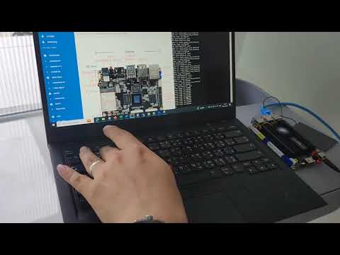
Installation of the module can be done by soldering it to the side of the board close to where the MicroSD card socket is located. Youyeetoo sent a 60W POE module for testing which required us to curve two of the pins before installation.

We could solder the PoE module after this little change, and we tested the board with a Zyxel GS1008HP 8-port POE switch. The X1 board will boot as soon as the Ethernet cable is plugged into the RJ45 jack.

Youyeetoo X1 power consumption
Although TDP and power consumption do not directly correlate, the Intel Celeron N5105 has a 10W TDP according to Intel Ark, and we’ll be running a real-world test to measure the power consumption of the Youyeetoo X1 with Wi-Fi, GPIO modules and sensors, and an M.2 NVMe SSD attached to the board.

We measured the board’s power consumption with a multi-function power meter. The results obtained from the adapter with a voltage of 12V DC, we can calculate the energy return from the equation P=IxV:
- Power Off – 47 mA or 564 mW
- Idle – 577mA or 6.9 Watts
- SBC bench (7-zip multi-thread) – 1.759 A or 21.55 Watts

Conclusion
Youyeetoo X1 board is a business-card single computer board powered by an Intel Celeron N5105 with several GPIO headers which we would not typically on most other x86 hardware. The board also features M.2 connectors, both M Key and E Key, to connect an SSD and/or a wireless module be it Wi-Fi or 4G LTE or SSD, as well as MIPI DSI and HDMI interface to connect a display or monitor with up to 4K resolution.
We tested GPIO, UART, I2C, SPI, and NFC successfully on the Youyeetoo X1, and it was mostly straightforward except for SPI which required us to enable SPI in the Linux kernel and rebuild it from source. In any case, this makes the Youyeetoo X1 SBC board suitable for edge computing and whether you are a maker, an IoT developer, or a system integrator the Youyeetoo X1 SBC could meet your requirements for projects such as industrial automation, IoT gateways, robotics, and more.
We’d like to thank Youyeetoo for sending the X1 SBC board with 8GB RAM and a 128GB eMMC flash, plus the 7-inch YYT-MIPI7LCD touchscreen display, and other accessories for review. The Youyeetoo X1 SBC can be purchased on Amazon, Aliexpress, and the company’s online store. Prices start at $109.99 for the 4GB RAM model without storage, and the model reviewed here goes for $139.99, while the YYT-MIPI7LCD display adds an extra $30.
CNXSoft: This post was translated, with a few edits and extra insights, from the original review on CNX Software Thailand by Arnon Thongtem, and edited by Suthinee Kerdkaew

Jean-Luc started CNX Software in 2010 as a part-time endeavor, before quitting his job as a software engineering manager, and starting to write daily news, and reviews full time later in 2011.
Support CNX Software! Donate via cryptocurrencies, become a Patron on Patreon, or purchase goods on Amazon or Aliexpress. We also use affiliate links in articles to earn commissions if you make a purchase after clicking on those links.


Looks great! But if i were to hang it on the wall running 24/7, how long should I expect it to last?
This is an important question for any “embedded” product.
If you blow plenty of fresh air around your wall, not with auto exhaust from a street, and keep cats and mice (apes, lions too) away from it, it should be 35 years fine. Was your ROI farther out than that?
That barrel connector would get soiled and the socket fail in portable use, but maybe you know how to clean and where to replace those 3-wire concentric barrel connectors (which Wikipedia doesn’t even acknowledge. ASUS uses them though. The parts just aren’t around at Digi-Key or have a special name?)
I remember Linaro engineers used SBCs in a build farm several years ago, and one said many boards would only last a few months, while others are still going strong. He was unwilling to mention which models failed often though. If I remember correctly that was in a Charbax YouTube video.
There is an error for the I2C code. This is the code for the relays.
Sorry about that. My bad. I’ve just fixed it.
Hi,
do you have the possibility to test the M.2 M-Key socket with a PCI-Express device via an adapter? The Lattepanda can use PCIe devices in the B and M-Key slots but is much more expensive.
Thank you!
Hi please use the new version bios
https://drive.google.com/drive/folders/18megQvD4DorZy_wnGV7Ti30OxDxdoge2?usp=sharing
“But since information about the SPI pinout is missing” – it appears to have been updated – here – https://wiki.youyeetoo.com/en/x1/windows/spi_driver