
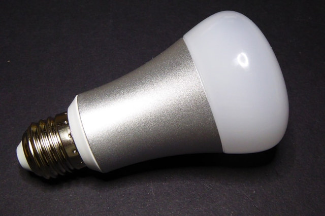
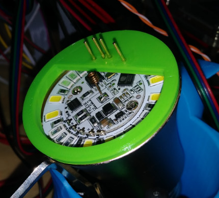
Karl here. I have to say that my favorite part of 3D printing is designing things from scratch. Recently a reader was asking about a way to flash a lot of Ai Lights on a project he was working on. I suggested 3D printing a jig that pressure fits pins. He didn’t have a printer, and we exchanged contact information and he sent me one of the lights and some pogo pins from Amazon.
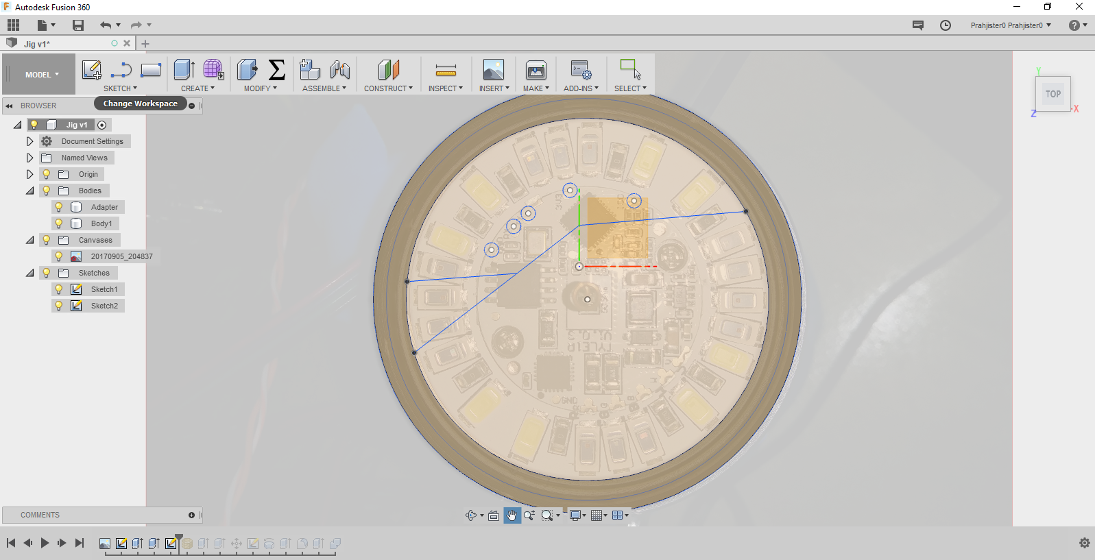
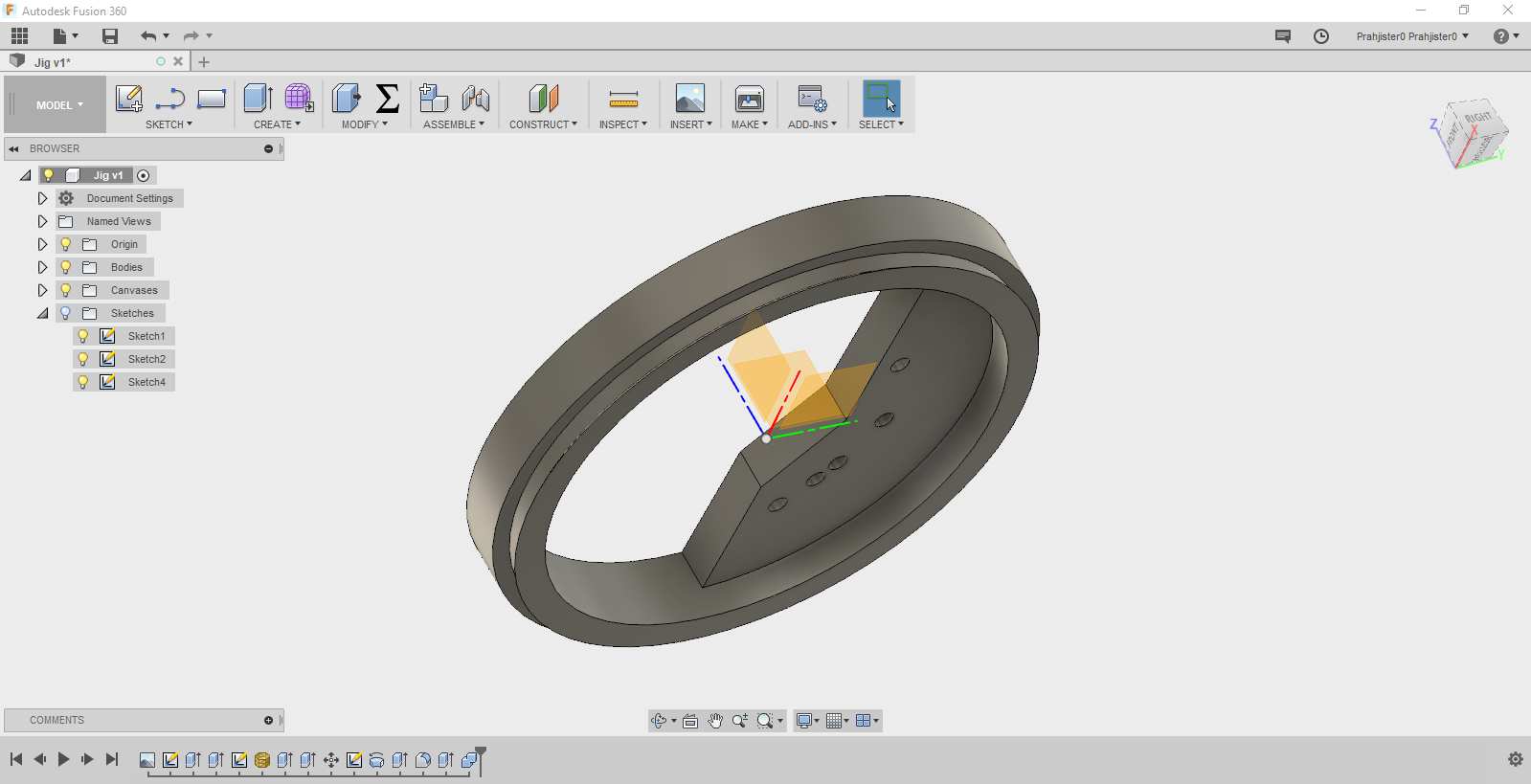
Design in Fusion 360
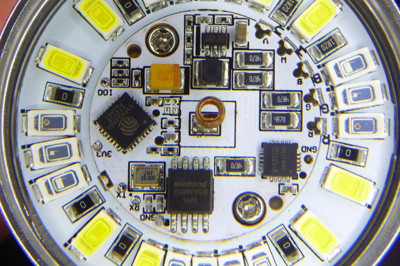
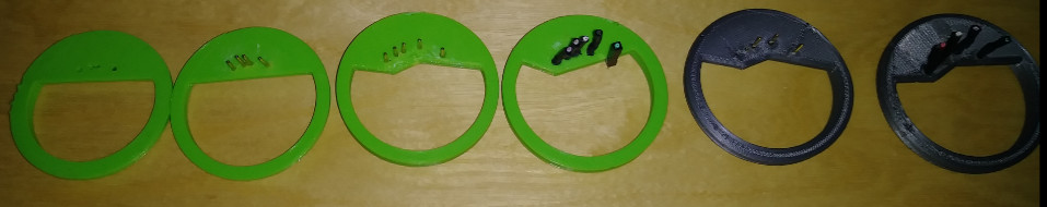
I started by taking a picture of the light to get my pin placement. I set a scale by measuring a known distance then printed and tested. It took about 3 iterations to get them to line up in real life. Keep in mind camera lenses distort reality and knew It would take a couple times. I would just let a few layers print then stop and line everything up. I had a mostly working prototype in a couple hours. I did have to go back and add an additional pin after I found out that 100 needed to be grounded when powering up so took a couple more tries to line that pin up. The first couple times pressing into place it is very snug. After 3 or 4 times it becomes easier to remove.
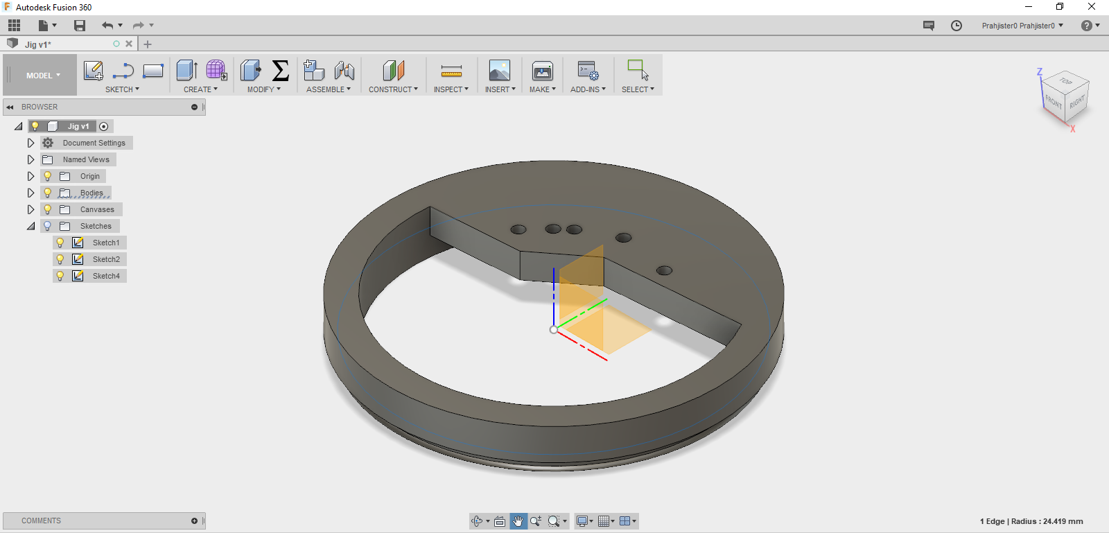
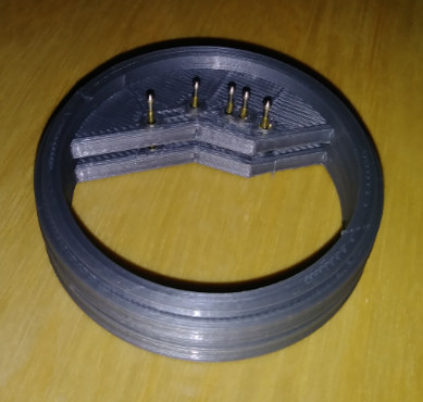
Building the Jig
I built this thing too many times, but I finally settled a reproducible method. First print at least 2 copies of the jig. Insert pins in jig then place on 2ng jig with pins up. 2nd jig is only for alignment and to keep straight. Once aligned super glue the pins to the jig and let dry. Do not get glue inside the pins or they will get stuck. When I was first putting this together I was doing it the other way, and glue kept on seeping down to the pins and making them stick. This method of gluing worked the first time.
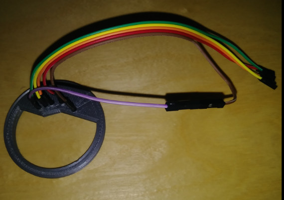
After gluing solder on your leads, use some shrink tube, and make sure to connect pin 100 to the ground. I thought it needed to be temporary, but I forgot to disconnect one flash. I test flashed the light about a dozen time with 100% success.
The method I used to connect is with the leads connected to PC, I press the jig in place slightly offset clockwise a couple degrees. Press in, then turn counter clockwise until you hear a click. When it clicks into the pads and PC dings it is ready to flash.
 This was a fun little project and if you would like to print it you can find it here.

Karl is a technology enthusiast that contributes reviews of TV boxes, 3D printers, and other gadgets for makers.
Support CNX Software! Donate via cryptocurrencies, become a Patron on Patreon, or purchase goods on Amazon or Aliexpress


Is this for the Xiaomi Yeelight RGBs ?? Interesting….
@James
That’s for A.I. thinker light bulb, unlikely to work out of the box for Xiaomi Yeelight, unless they use the same PCB, but it could be adapted.
Edit: Finally no… Xiaomi Yeelight design is completely different and based on Marvell WiSoC -> https://photos.app.goo.gl/2OAbLpOArg6Kijdl2
Looks great! Do you have a link to where you got the pogo pins or even their dimensions? I got some recently but they are very slim and very long.
I’m not sure if it could be pulled off with the system resources on an ESP8266 but a smart-bulb would make one sneaky wi-fi sniffer/pineapple. Swap out the bulb in a lamp and at least track wifi mac addresses going through the area.
@Conor
I think he bought the ones linked in the introduction with the anchor link “pogo pins”.
My old eyes completely missed the link. Thanks!