
FriendlyELEC has launched many cool NanoPi development boards such as NanoPi NEO2, NanoPi A64, or more recently NanoPi Duo based on Allwinner H- or A- series ARM processors, as well as some models based on Samsung/Nexcell or Amlogic SoC.
The company has now launched two other NanoPi products that are a bit different since they are systems-on-module – or could even be considered minimal development boards – with namely NanoPi NEO Core powered by Allwinner H3 quad core 32-bit processor, and NanoPi NEO Core2 based on Allwinner H5 quad core 64-but processor.
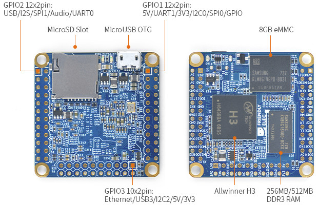
NanoPi NEO Core
Specifications:
- SoC – Allwinner H3 quad core ARM Cortex-A7 processor up to 1.2GHz with Mali-400MP GPU
- System Memory – 256MB or 512MB DDR3 RAM
- Storage – NC/8GB/16GB/32GB eMMC flash, micro SD slot
- USB – 1x micro USB OTG port also used for power input
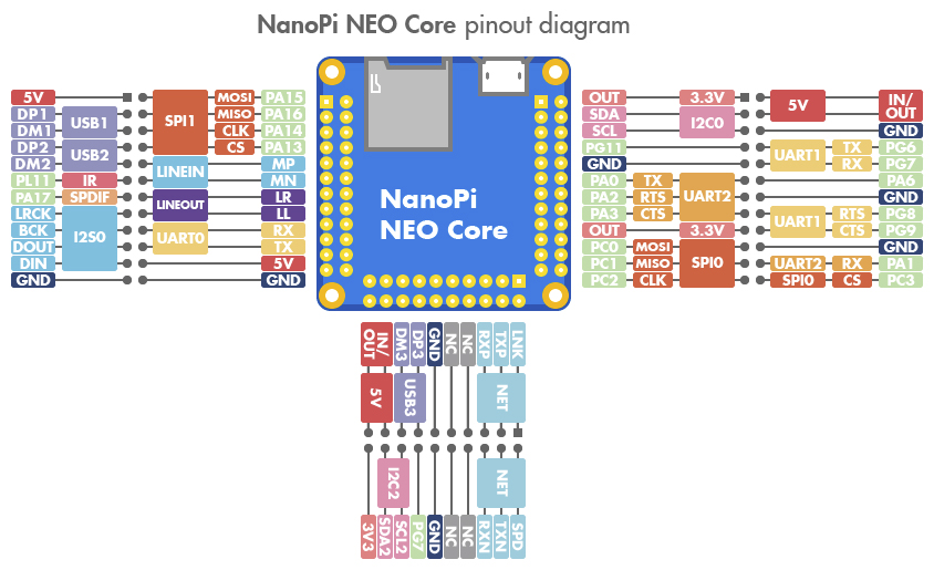
- Expansion – 2x 2.54mm pitch 24-pin headers, 1x 2.54mm pitch 20-pin header exposing:
- Connectivity – 10/100M Ethernet
- USB – 3x USB Host port
- 4-pin debug serial port
- 4-pin audio input/output port
- UART, SPI, I2C, GPIO, IR etc…
- Power Supply – 5V/2A
- Dimensions – 40 x 40mm
- Temperature measuring range – -40 to 80
A Ubuntu Core Xenial image with Linux 4.14 is provided, and documentation can be found in the Wiki.
The board is sold for $7.99 with no flash and 256MB RAM, but a version with 512MB RAM and 8GB eMMC flash is also offered for $10 extra.
NanoPi NEO Core2
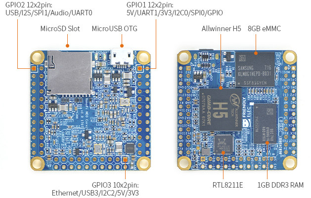 The 64-bit version of the board has basically the same specifications, except for the different processor, more memory, and an extra Realtek RTL8211E Gigabit Ethernet transceiver:
- SoC – Allwinner H5 quad core ARM Cortex-A53 processor with a Mali-450MP GPU
- System Memory – 512MB or 1GB DDR3 RAM
- Storage – 8GB/16GB/32GB eMMC flash, micro SD slot
- USB – 1x micro USB OTG port also used for power input
- Expansion – 2x 2.54mm pitch 24-pin headers, 1x 2.54mm pitch 20-pin header exposing:
- Connectivity – Gigabit Ethernet via RTL8211E transceiver
- USB – 3x USB Host port
- 4-pin debug serial port
- 4-pin audio input/output port
- UART, SPI, I2C, GPIO, IR, etc…
- Misc – 2x LEDs for power and system status
- Power Supply – 5V/2A
- Dimensions – 40 x 40mm
- Temperature measuring range – -40 to 80
 Both NanoPi Core and Core2 modules appear to be pin-to-pin compatible. NanoPi NEO Core2 runs a different firmware image also based on Ubuntu Xenial with Linux 4.14, and more technical info is listed in the Wiki. I also suspect both boards are software compatible with NanoPi NEO / NEO2, so other firmware such as Armbian images may also run without modifications.
FriendlyELEC does not offer a version without flash, and actually only one version is for sale now with 1GB/8GB configuration for $24.99.
Mini Shield for NanoPi NEO Core/Core2
You could wire your NEO Core(2) board yourself, if you want to get started quickly, or something that works out of the box with USB, Ethernet, and audio connectors, as well an M.2 slot, the Mini Shield is here to help with the following specs:
- Storage – 1x M.2 2242 SSD socket
- Connectivity – 1x Ethernet port
- USB – 2x USB Host
- Audio – audio input and 1 x audio output
- Expansion – 2x 13-pin GPIO header
- Debugging – 1x Serial debug port and
- Misc – 1x button, 1x IR receiver
- Dimensions – 85 x 56 mm (Raspberry Pi form factor, compatible with enclosures)
Mini Shield can be purchased as option for $10.99 extra on NanoPi NEO Core or Core2 product pages. It has its own Wiki page where you can find additional hardware details.

Jean-Luc started CNX Software in 2010 as a part-time endeavor, before quitting his job as a software engineering manager, and starting to write daily news, and reviews full time later in 2011.
Support CNX Software! Donate via cryptocurrencies, become a Patron on Patreon, or purchase goods on Amazon or Aliexpress. We also use affiliate links in articles to earn commissions if you make a purchase after clicking on those links.


NanoPi Neo Core2 has a H5-Quadcore-CPU – and not H6 🙂
but the Feature-Icons for the Core2 show H5 OctaCore on their webpage 🙂 – couldnt be right 🙂
M2 Port on the MiniShield seems to be full-size against the half-size of the NanoPi Duo MiniShield
Is the M2 Native?, or is it another usb to sata chip?
@Jeroen
According to the wiki page it uses a JMS567 USB to SATA IC on the Mini Shield.
How do they connect the M.2?
Board description says Qt application and gyi support but it didn’t have any HDMI or VGA port.
Excruciating that they hobble it with 16-bit DDR interface.
@Philipp Blum
USB to SATA as mentioned by @Abbadon .
@Pushpendra
I think a lot of copy/paste is done for the Wiki, so probably old text from NanoPi boards with HDMI or other display I/F.
The NanoPi Neo Core provides no headers, so you have to get & solder them yourself?
The NanoPi Neo Core 2 has headers, but is quite expensive, making the combination no too interesting.
Pity … I would certainly buy a M2-capable 64-bit setup of 25 USD.
You can use SPI or I2C LCD, we hava a demo( https://github.com/friendlyarm/QtE-Demo ), see the file “https://github.com/friendlyarm/QtE-Demo/blob/master/boardtype_friendlyelec.cpp”.
@Pushpendra
I like NanoPi’s – their boards are good
At this point they should have looked at adding a processor with USB3 to their product mix.
Rock64 is now the most attractive kit at a very good price point.
@Lalith
Things to come, and busy programmers.
M.2 SATA?!? Woohoo, finally!
@mindee
thanks for ur kind information @mindee
At this form-factor and this price-point, the VoCore2 is a much better option.
https://www.indiegogo.com/projects/vocore2-4-coin-sized-linux-computer-with-wifi
@Mike Schinkel
I don’t get it. Same with the other commenters excited about ‘M.2’…
M.2 is just a rather boring mechanical connector. There’s no performance associated with it, this connector can transport various protocols and the only one used here is SATA. Slow SATA, ultra slow SATA, USB2 SATA.
It’s the same as attaching an SSD in an USB enclosure to any other USB2 only SBC. So why being excited?
The good news:
– while it’s USB SATA here, UAS can be used since FriendlyELEC took care to use a good bridge chip (they chose JMS567)
– FriendlyELEC seems to have gotten those JMS567 that are JMS578 in reality (USB product ID 0x0578 instead of 0x0561). Both chips are more or less the same but the latter is able to support TRIM
– so after applying latest JMS578 firmware upgrade TRIM should then work here with M.2 SATA SSDs that support it (most probably all except those cheap/crappy ones the majority of SBC users buys that are in reality just eMMC chips with a SATA interface, their names start often with ‘King’)
– TRIM is very important if an SSD is used as data logger as soon as the amount of data written to the SSD over its entire lifetime exceeded the SSD’s capacity. Since then SSDs without TRIM support get very inefficient, write amplification increases a lot and the SSD wears out magnitudes faster. Usually there’s also a performance drop involved but not here since the USB2 SATA implementation is already the main bottleneck
Besides that I’m curious how well ‘Gigabit Ethernet on pin headers’ will work with the Core2.
@Da Xue
Why should 16-bit memory interface vs. 32-bit matter with the use cases these boards are made for? There’s fortunately no HDMI so what should be high memory bandwidth needed for?
stacking them on top of each other to build a little cluster/tower.. possible?
@mindee
Can you please confirm that if someone buys the NEO Core together with the Mini Shield that then the Core will be shipped with presoldered pin headers?
@tkaiser:
About the excitement about M2 (and slow USB2 SATA): for me, the compact size & on-board is also important; no bulky USB hanging from the (one) USB port my Nanopi has.
BTW: My *assumption* is that the USB2 SATA M2 SSD combination is still faster and more reliable than a flash card.
Faster? Sequential performance with optimal settings means ~40MB/s maximum, random IO performance depends on the SSD used but here the USB layer again will decrease performance but in a rather linear way (use an SSD that is able to achieve 10,000 random IOPS at 4K size on a good SATA port and you’ll end up with 2,000 behind such an UAS capable USB-to-SATA bridge — numbers based not on assumptions but on tests).
So for anything that really needs high IO performance this here is not the best option though keeping up with some ‘native SATA’ SBC implementations like Allwinner A20 boards since their ‘native SATA’ is just a little bit faster than USB2-SATA but will be easily outperformed by USB3-SATA.
More reliable? Depends. If you choose to buy crappy SD cards then yes, this will always be true. But you can also try to buy good and genuine SD cards (they’re not that much more expensive if at all) and then such a card might be more reliable than the ‘cheapest M.2 SSD possible’ especially when the manufacturer’s name starts with ‘King’.
There exist M.2 SSDs that just expose some eMMC, fake thermal readouts and do not correctly implement wear out prediction (all the good brands expose monitoring parameters through SMART that allow you to check how much data has really been written to your SSD and how much of its lifetime is already over in percentage)
If it’s about preventing early wear out the real difference between ‘dumb’ flash storage like SD cards or USB pendrives and good SSDs is TRIM when the amount of data to be written over the device’s lifetime exceeds its capacity. And in general it’s important to minimze write amplification: https://forum.openmediavault.org/index.php/Thread/20797-Add-drives-to-an-existing-array-then-extend-the-existing-partition-file-system/?postID=162246#post162246 (writing small chunks of data all the time instead of ‘bundling’ them and writing them periodically in a batch can resuilt in an SSD wearing out thousand times faster)
The Mini Shield’s M.2 slot allows to add some ‘real SATA storage’ to such a board that will fit in every RPi enclosure around (think of DIN Rail and stuff like that). For me buying ‘as cheap as possible’ and choosing questionable/unreliable SSDs on Aliexpress or eBay is not an option (since I deal with data losses/recovery for a living). Choosing good M.2 2242 SSDs is still somewhat expensive (and if you choose performant one there is a high probability that you choose an overheating one even in idle — there’s a reason M.2 SSDs and devices with this slot start to ship with heatsinks).
So I personally explored a different route checking for affordable TF cards with good warranty handling and reducing both amount of data and write amplification by changing software/settings.
A data logger running off eg. an 128GB EVO+ TF card with optimized settings and btrfs/zlib will live a lot longer than some cheap/crappy M.2 SSDs using ‘average settings’ (ext4 with standard commit interval and no software design changes to reduce write amplification). This applies especially to SSDs when TRIM can not be used since then they’re essentially as dumb as any SD card and move around data that has been long deleted as part of the wear leveling and garbage collection process.
Most probably people keen on using M.2 SSDs on the Mini Shield always buying as cheap as possible will end up with KingSpec for example: http://www.kingspec.com/products_detail/productId=60.html
Users should know that reputable SSD manufacturers specify a TBW (Terabytes written) value for each of their products. Usually the larger the capacity, the larger the TBW value. These TBW numbers are specified by JEDEC (JESD218B) and differentiate between an enterprise (high focus on random IO) and client profile (almost only sequential write access which is a bit surprising to me since this is not what happens with SSDs as OS drive)
A great Samsung 850 Pro with 256 GB capacity comes with a 150 TBW rating. These ratings from reputable SSD manufacturers take into account that write amplification is key and these TBW ratings can be considered worst case conditions with an insanely high write amplification. German c’t magazine tested a couple of SSDs for their write endurance and above Samsung 850 Pro with a guaranteed write endurance of 150 TB failed after 9.1 PB (that’s lasting 60 times longer than specified — the relevant SMART attribute indicating lifetime expectation in percentage was already at 0 for most of the whole test).
What do the ‘buy cheap buy twice’ people get that choose on Aliexpress and eBay the most unreliable stuff possible? No TBW rating but plain BS: KingSpec talks about ‘8 years (100GB/day)’ for all three SSDs with 32, 64 and 128GB. This is already an indication that these are pure BS numbers since smaller capacity == lower endurance. Then these numbers do not take the write amplification problem into account but even if we just do the math and calculate 8 * 365 * 100 we know that these are even more BS numbers since the result would be 292TB even for the 32GB SSD (while an eight times larger high quality Samsung Pro only specifies 150 TB).
Adding to that: I’ve never encountered SMART data from these SSDs that were not totally bogus which is a real problem since one of the advantages of SSDs over dumb flash storage is that their controllers report lifetime prediction through SMART queries.
I don’t worry for this. For having tortured gigabit connections for a while making tens of knots between some wires, the encoding is extremely tolerant to abuses. What you need to avoid in fact is long lines not respecting pairs. But even 50cm of flat wire (non-twisted pair) will not report any measurable error rate. Some mini-pcie boards like the dual gig i350-based boards also provide gigabit over pin headers and work quite fine.
There are many lists for fastest Sdcard in the Camera, Video market but SBC, embedded etc are more interest in A1 rating and random read/write speed, as that is what is need.
But I will link to a article that is meant for Camera, Video users, as it may help beginners understand the different ratings and interfaces of SDcards better.
https://havecamerawilltravel.com/photographer/fastest-sd-cards/
@theguyuk
Related by specific to micro SD cards for development boards: https://www.cnx-software.com/2017/06/13/micro-sd-cards-for-development-boards-classes-tools-benchmarks-reliability-and-tips-tricks/
And a final elaboration on why (reducing) write amplification matters:
Good SSDs expose what’s happening at the flash layer. SSDs from all reputable vendors correctly report how much data has been really written at the flash layer in contrast to the filesystem layer. In the below example that’s SMART attribute 241 called ‘Total_LBAs_Written’ (one LBA is 512 bytes in sizes — never trust in this but simply test it with the SSD you bought). A smartctl call at the begin of the test showed that I’ve written to this Samsung EVO 840 already 7.6 TB:
That’s also the reason why SMART attribute 177 ‘Wear_Leveling_Count’ is already at 51 (starts at 100 to decrease continually based on amount of data written and internal controller’s lifetime prediction).
Test for different ratio of write amplication is easy: Let files of different size write at the fs layer each 5 times, query ‘Total_LBAs_Written’ before and after and report the difference. I’m using random data instead of /dev/zero as source since those SSDs that work with internal compression (Sandforce controllers for example) would otherwise not really store data at all. Simple script producing simple output:
So with 1MB large chunks written 5 times to disk we have an amount of 5120 KB written at the fs layer… but at the flash layer 5340 KB were written (the difference is mostly since updating filesystem structures is part of the task, have this in mind if you use OS images that do not use ‘noatime’ and ‘nodiratime’ mount options since even accessing files will always result in unnecessary wear out).
With 128KB chunks we’re writing 640KB at the filesystem layer but 840KB at the flash layer. But the lower we go with the size of data chunks the more write amplification increases. With 16KB we’ve already an 1:3.5 ratio, with 4K (this is the SSD’s native page size reported by this test!) we’re at 1:11 (20 KB vs. 220 KB in reality) and everything below the page size will result in an insanely high write amplification.
While writing 5 times just a single byte to flash media (which results under above conditions in a write amplification of 1:44000 –> 5 bytes at the fs layer result in 220KB written at the flash layer) is not that typical on a data logger writing just a bunch of bytes every few seconds is. And then the difference between OS images that take care of this stuff and those that do not makes a difference of an SSD wearing out hundred or even thousand times faster or not.
That’s why being able to query the device through SMART and getting correct values is important. Same with OS images that care of this behaviour since even if you can not monitor unnecessarily high write amplification it will happen anyway if you do not take countermeasures (choose your OS images wisely).
@cnxsoft
Has anyone done a usb3 to UFS card reader yet?
I’m only concerned about potential GbE TX/RX delay adjustments (without those some boards show horribly low performance or no network connection with GbE at all) but hope that PCB design took care of this here and it’s sufficient to simply use traces of exactly same length to connect the MagJack to the board’s pins.
If that’s the case and Core2 uses the primitive VDD_CPUX regulation jumping between 1.1V and 1.3V then all OS images suitable for NanoPi NEO Plus 2 (not NEO2) will work without issues. Of course a better idea is an own DT but that’s more or less just deleting the Wi-Fi entry and turning usb0 from host mode back into otg mode.
@noone
Vocore2 can’t run IoT apps designed for Scratch or Node.JS? Not enough CPU power and RAM. Some won’t even consider NanoPi since it doesn’t have USB3 and octacore ARM64. Also less than 4 GB of RAM with no OpenGL 4.6 GUI. There needs to be platforms for everyone.
Some more details about headers:
Friendlyarm now have Neo Core and Neo Core 2 starter kits for sale case, shield, heatsink, screws, Neo Core 2 , USB2UART, micro USB.
Are they were smart enough to route correctly the RTC battery backup at any of their board ? The boards are still expensive comparing to NanoPi Neo
Friendlyelec are now listing a 0.96’128×64 OLED for NanoPi NEO Core/Core2 in their latest section.