A few months ago I reviewed ANAVI Light pHat for Raspberry Pi which allows you to control an LED RGB strip from the popular development board. However, if all you need is to switch the RGB LED light on and off, or change the color, the hardware is clearly overpowered for the tasks.
So Leon ANAVI designed another board based on ESP8266 – ANAVI Light Controller – which does the same thing with lower cost and more power efficient hardware. Leon sent me a sample for review, so let’s see what we’ve got.
ANAVI Light Controller Starter Kit Unboxing
I received a package for the Starter kit that’s offered for $39 on CrowdSupply.
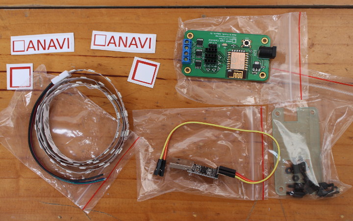
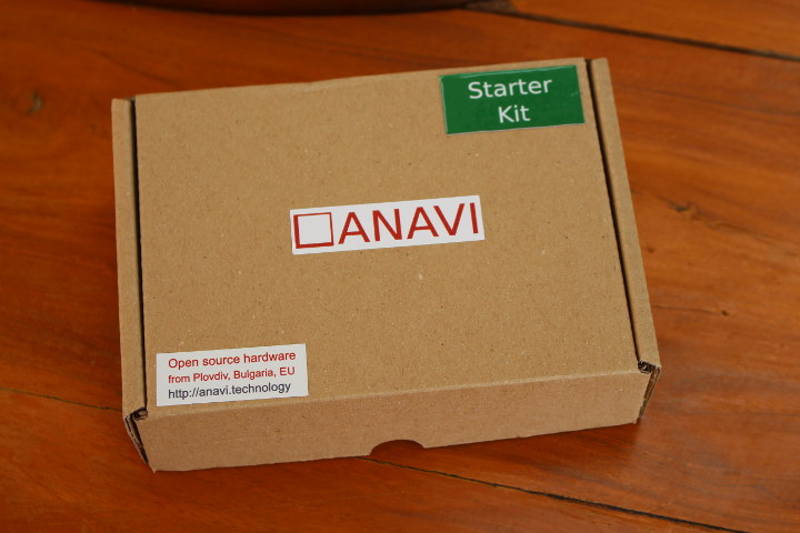 We’ve got the main board, a USB debugging, an acrylic enclosure with screws and spacers, a one meter RGB LED strip, and some stickers inside the package.
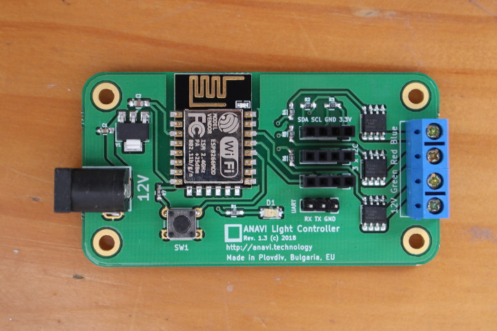
If we have a close look at the board we have from right to left: a 12V power jack, SW1 button connected to GPIO0, an ESP8266 module (ESP-12E), D1 user LED, three I2C headers for sensor, a 3-pin serial header for programming, and the 12V + RGB terminal block, where we’ll connect our LED RGB strip.
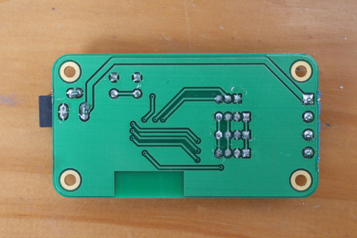
The back of the board is pretty bare.
ANAVI Light Controller Starter Kit Assembly
I won’t go into much details here, since everything is straightforward. Start by adding the space, then fit the acrylic case on top, before using a precision screw driver to connect the LED RGB light strip.
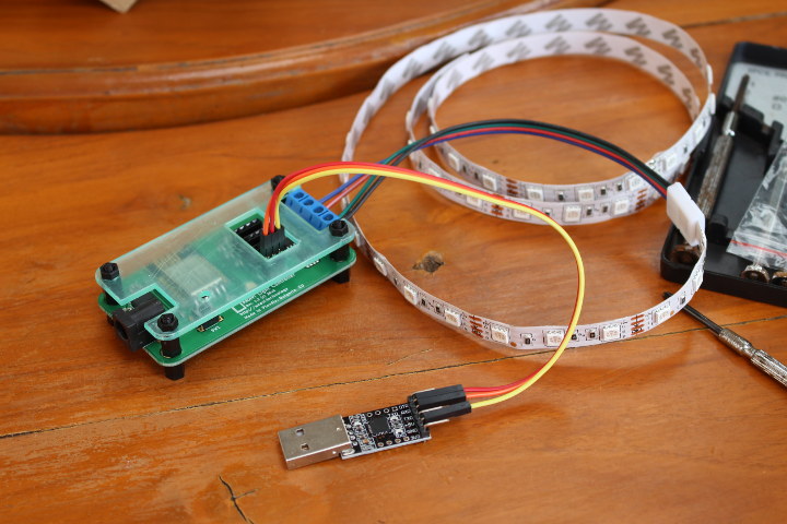
We can also connect the USB to serial board using Tx, Rx and GND pins. However, I found some of the light strip wires would easily move out, so I stripped the wires a little more.
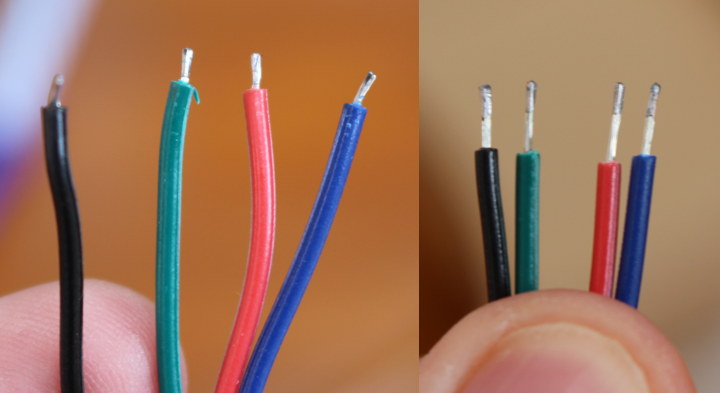 I inserted the wires once again, tightened the screws, and it looks like everything holds firmly into place.
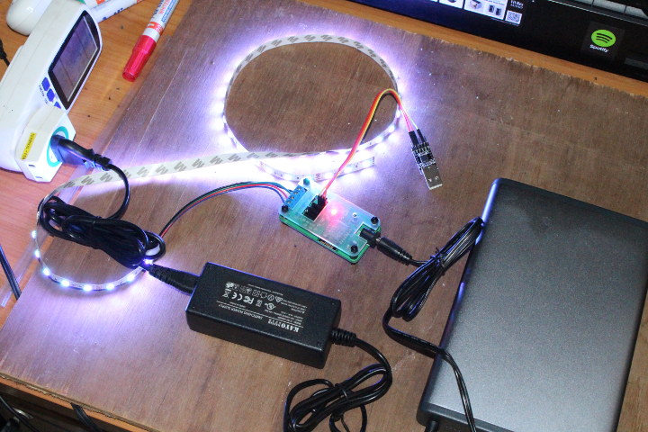
You’ll also need to find your own 12V power supply. I did not remember having any, so instead I used a 12V power bank (MAXOAK K2 laptop power bank), and you see the the strip light up with white color upon connecting the power.
ANAVI Light Controller Arduino Demo
The board ships with a default Arduino sketch that can receive MQTT commands to control the light strip. The sample is supposed to create a access point called “ANAVI Light Controller”, but either I could not see it, or my phone would only detect it a very short period of time, and I’d have to hurry to complete configuration. Yet after it would still not work. It turns out the board does not draw enough power from the 12V output, so the power bank thinks the “computer/laptop” connected to it is turned off, and automatically turns itself off.
But then I remember I purchase a 5V/8A – 12V5A switch mode power supply (SMPS) a few years ago, and once I switched to it instead of the power bank, everything went smoothly.
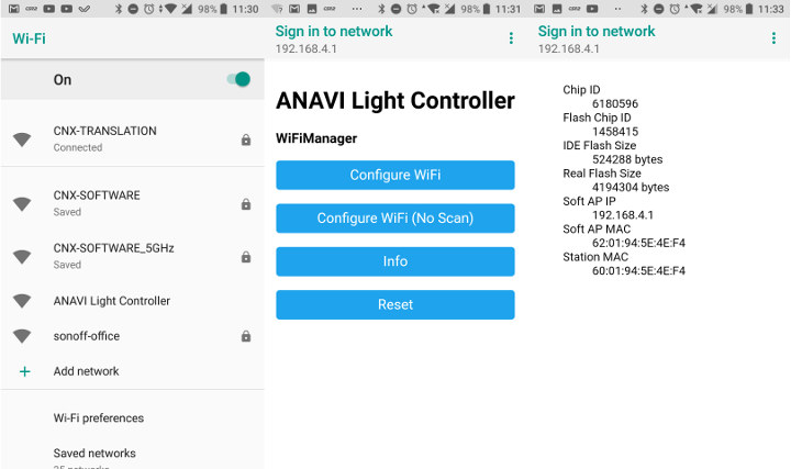
First connect ANAVI Light Controller SSID, and you should soon be asked to login which will bring out the WiFi Manager web interface. If you select the Info button, you’ll see some details about your board including the chip and flash chip IDs, flash size, and MAC addresses.
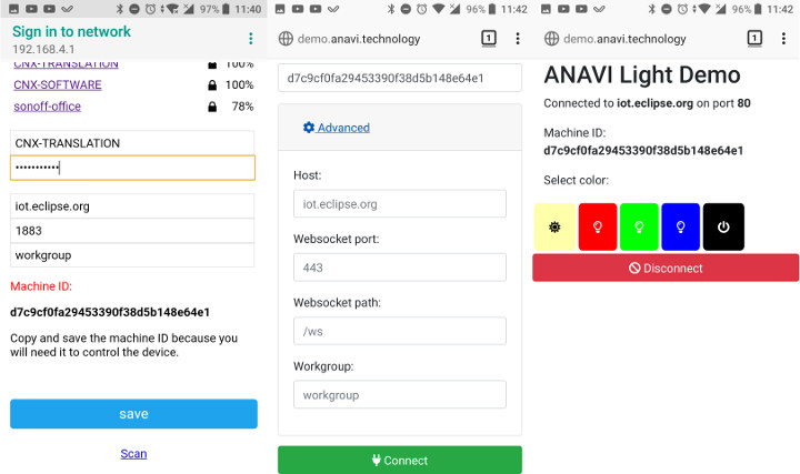
But you can safely skip that part, and instead tap/click on Configure WiFi, which will scan for your access points, and allow you to optionally change the MQTT server parameters. I left that part unchanged and use iot.eclipse.org server. Make sure you copy the Machine ID before clicking on save, as we’ll need it for the next step.
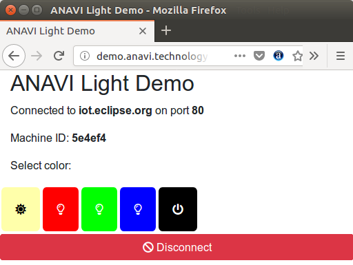
Now you can open a web browser, and go to demo.anavi.technology where you can past your Machine ID, and modified the MQTT server settings using the Advanced options in case you changed those in the previous step. Now click on connect to get the user interface with the button to turn on and off the light, and change color to red, green or blue.
Leon shot a video to demo the whole initial setup for his demo app.

I also connected the serial console (/dev/ttyUSB0 with 115200 8N1) to show some of the output for reference. That’s the output while booting the board after having setup the connection to my WiFi router.
|
1 2 3 4 5 6 7 8 9 10 11 12 13 14 15 16 17 18 19 20 21 22 23 24 25 26 27 28 |
mounting FS... mounted file system *WM: Adding parameter *WM: server *WM: Adding parameter *WM: port *WM: Adding parameter *WM: workgroup *WM: Adding parameter *WM: *WM: *WM: AutoConnect *WM: Connecting as wifi client... *WM: Using last saved values, should be faster *WM: Connection result: *WM: 3 *WM: IP Address: *WM: 192.168.0.118 connected...yeey :) local ip 192.168.0.118 MQTT Server: iot.eclipse.org MQTT Port: 1883 Attempting MQTT connection...connected ----- Machine ID: d7c9cf0fa29453390f38d5b148e64e1 ----- |
And the MQTT messages, once we start pressing the buttons in the demo website:
|
1 2 3 4 5 6 7 8 9 10 11 12 13 14 15 16 17 18 19 20 21 22 23 24 25 26 27 28 29 30 31 32 33 34 35 36 |
Message arrived [d7c9cf0fa29453390f38d5b148e64e1/action/rgbled] { "color": {"r"} Red: 255 Green: 255 Blue: 255 Message arrived [d7c9cf0fa29453390f38d5b148e64e1/action/rgbled] { "color": {"r"} Red: 255 Green: 0 Blue: 0 Message arrived [d7c9cf0fa29453390f38d5b148e64e1/action/rgbled] { "color": {"r"} Red: 0 Green: 255 Blue: 0 Message arrived [d7c9cf0fa29453390f38d5b148e64e1/action/rgbled] { "color": {"r"� Red: 0 Green: 0 Blue: 255 Message arrived [d7c9cf0fa29453390f38d5b148e64e1/action/rgbled] { "color": {"r" Red: 0 Green: 0 Blue: 0 Message arrived [d7c9cf0fa29453390f38d5b148e64e1/action/rgbled] { "color": {"r" Red: 255 Green: 255 Blue: 255 Message arrived [d7c9cf0fa29453390f38d5b148e64e1/action/rgbled] { "color": {"r"} Red: 255 Green: 0 Blue: 0 Message arrived [d7c9cf0fa29453390f38d5b148e64e1/action/rgbled] { "color": {"r" Red: 0 Green: 255 Blue: 0 Message arrived [d7c9cf0fa29453390f38d5b148e64e1/action/rgbled] { "color": {"r"} Red: 0 Green: 0 Blue: 255 |
If you want to reset to access point mode, simply press SW1 button for 10 seconds until the red LED light becomes solid.
ANAVI Light Controller is Open Source – Let’s Customize it!
One advantage of the solution is that everything is open source from the hardware (KiCad) to the firmware (Arduino) and the cloud software (HTML5), so let’s try to make some simple changes starting with the Arduino sketch. I’ll assume you have already installed Arduino Core for ESP8266.
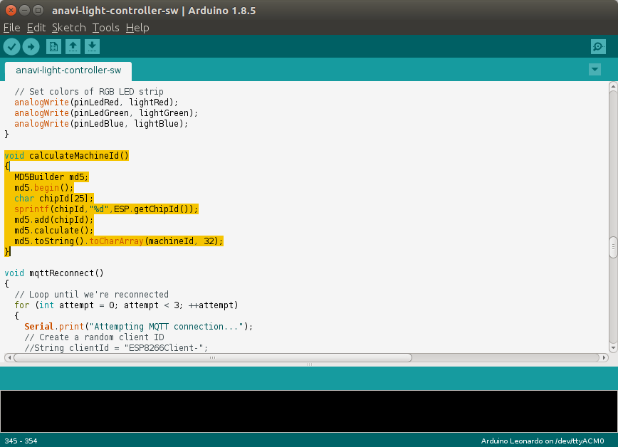
I found the Machine ID string to be a little complicated, and if we look at the code, it’s because it’s taking ESP8266 chipId (last three digit of the MAC address in decimal form) through an MD5 checksum. It’s done for better security, but considering it’s not salted, there’s only an illusion of security, as it would be easy enough to create a lookup table.
So instead, for the purpose of this demo ,I decided to simply the code, and just use the hex version of the chip ID as the machine ID. The function is then much simplified.
|
1 2 3 4 |
void calculateMachineId() { sprintf(machineId,"%x",ESP.getChipId()); } |
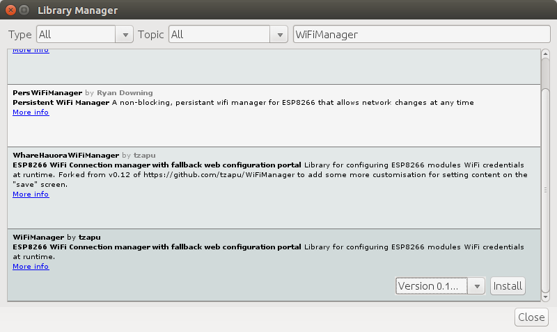
When I first try to build the sample, I have some errors, simply because we need to install some libraries first, by going to Sketch->Include Library->Manage Libraries, and search for the ones we need.
I had to install the 5 libraries below:
- WiFiManager by tzapu – ESP8266 WiFi connection manager with fallback web configuration portal
- ArduinoJson – A JSON library for Arduino (Important: Install version 5.13.1, not the latest beta version selected by default).
- PubSubClient – Arduino Client for MQTT
- Adafruit HTU21DF Library – Arduino library for the HTU21D-F sensors in the Adafruit shop
- Adafruit APDS9960 Library – Arduino drivers for APDS9960 gesture sensor
Now we can click on the Verify button to make sure it compiles, and then Upload it using /dev/ttyUSB0 with 115200 baurate, and select NodeMCU (ESP-12E). However, I kept getting the following error message
|
1 2 3 4 5 6 |
Sketch uses 351414 bytes (33%) of program storage space. Maximum is 1044464 bytes. Global variables use 38576 bytes (47%) of dynamic memory, leaving 43344 bytes for local variables. Maximum is 81920 bytes. warning: espcomm_sync failed error: espcomm_open failed error: espcomm_upload_mem failed error: espcomm_upload_mem failed |
That means a connection issue with ESP8266 board. I tried to play with SW1 switch, but nothing did the trick, Finally I was made aware of the exact procedure to follow:
- Select Tools > Generic ESP8266 Module with Flash mode: DIO, Flash frequency: 40MHz, CPU frequency: 80MHz, Flash size: 512K (64K SPIFFS), Debug port: Disabled, Debug level: None, Reset method: ck, Upload speed: 115200, Port: /dev/ttyUSB0
- Click on Upload or press Ctrl+U
- Press and hold SW1 button, and connect the 12V power supply, and only release SW1 once the upload has started.
I could finally upload my modify Sketch to the board, and was able to control the LED strip using the new Machine ID (i.e. chip ID) for my board: 5e4ef4.
All good, but let’s not stop there, as Leon also released the source code for the web interface written in HML5 and leveraging Bootstrap 4.1.1, jQuery 3.3.1, Popper.js 1.14.3, and Paho (paho.mqtt.javascript) v1.0.3 libraries.
I first retrieve the code from github:
|
1 2 |
git clone https://github.com/AnaviTechnology/anavi-light-demo cd anavi-light-demo |
and setup a new subdmain to control the lights: http://rgbled.cnx-software.com.
I decided to add a new pink button. So I just looked for the code for the red button, and modified three files:
- index.html:
|
1 2 3 4 5 6 7 8 |
<div class="row"> <button id="buttonColorMax" class="buttonColor"><i class="fa fa-sun"></i></button> <button id="buttonColorRed" class="buttonColor"><i class="far fa-lightbulb"></i></button> <button id="buttonColorGreen" class="buttonColor"><i class="far fa-lightbulb"></i></button> <button id="buttonColorBlue" class="buttonColor"><i class="far fa-lightbulb"></i></button> <button id="buttonColorPink" class="buttonColor"><i class="far fa-lightbulb"></i></button> <button id="buttonColorOff" class="buttonColor"><i class="fa fa-power-off"></i></button> </div> |
- css/styles.css:
|
1 2 3 |
#buttonColorPink { background-color: #FF00FF; } |
- js/demo.js
|
1 2 3 4 |
$('#buttonColorPink').on('click', function (e) { e.preventDefault(); changeColor(255, 0, 255); }); |
Now I can go to my own website to connect to 5e4ef4 board, and click on that brand new Pink button…
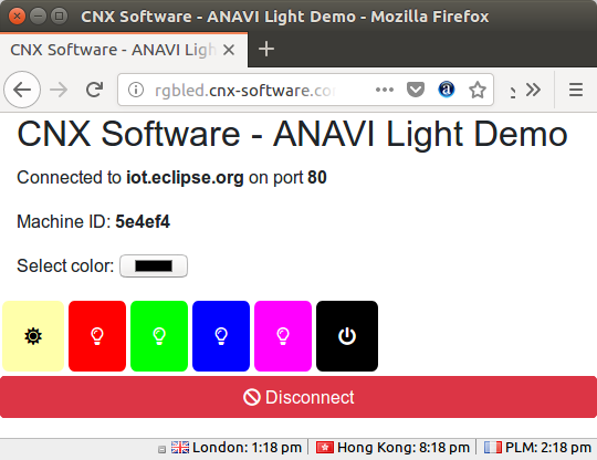 … in order to change the lights color to pink. Success! I also gained a color picker in the process, which was added by Leon, but the code was not updated on his live demo website.
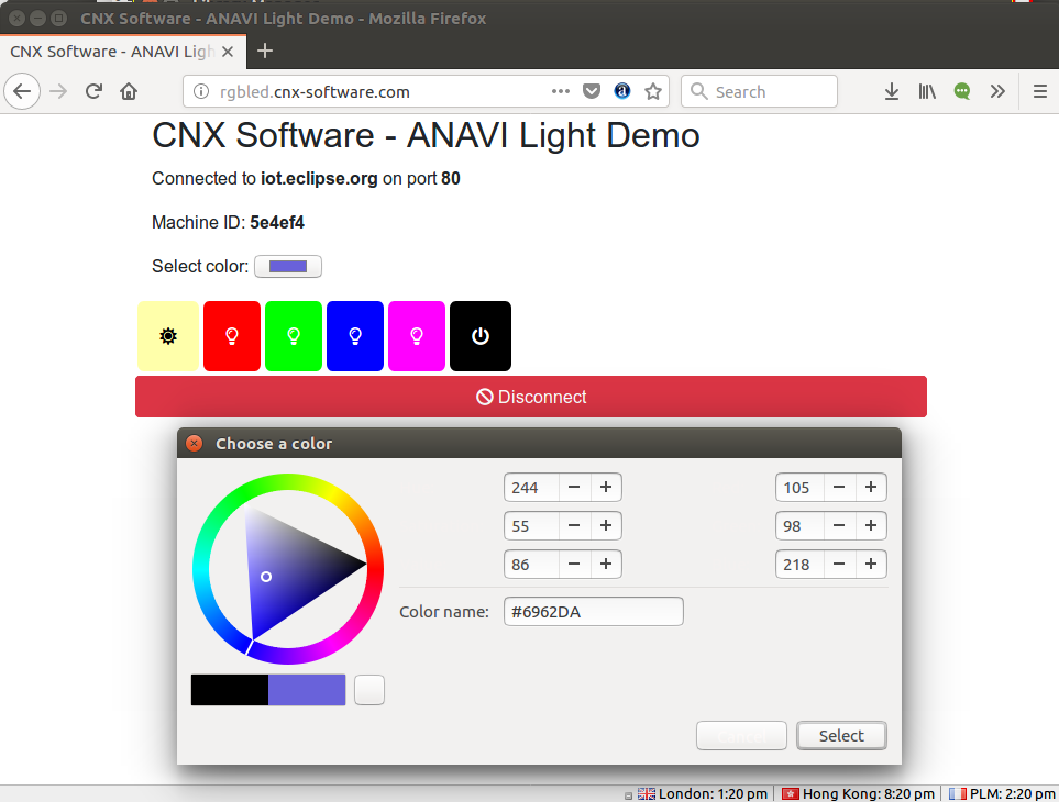 The only downside is that any of you guys can now easily control my RGB LED strip since you can just access my test domain, or anavi demo web page, input my chip ID, and change the color or turn it off at will. So this works as a demo, but some better access control is needed, unless you plan to run this in your own LAN instead.
Finally, I’ve shot a short demo to show the board in action with my custom Arduino firmware and cloud software.
If you already own an RGB LED strip, you can also get ANAVI Light Controller board only for $25 plus shipping, instead of the complete starter kit.

Jean-Luc started CNX Software in 2010 as a part-time endeavor, before quitting his job as a software engineering manager, and starting to write daily news, and reviews full time later in 2011.
Support CNX Software! Donate via cryptocurrencies, become a Patron on Patreon, or purchase goods on Amazon or Aliexpress. We also use affiliate links in articles to earn commissions if you make a purchase after clicking on those links.




Nice. That’s a very similar small project I’ve made with esp8266 and p9813, but a bit more configurable. I wanted to remove arduino and do everything with esp8266, but then boredom kicked in.
http://www.stupid-projects.com/control-rgb-strips-with-wifi-esp8266-and-arduino/
Thanks 🙂 I hope my project will inspire you to continue your stuff too 🙂
If you can add live cam so that we can see when we change color that will be awsome
Yes, the other open source hardware board ANAVI Light pHAT is more suitable for webcam. It was designed specially for Raspberry Pi. It does the same job for controlling 12V RGB LED strip and you can easily add a web cam to the Raspberry Pi 🙂
Wouldn’t H801 be a better deal?
it is also esp8266 based, and can be bought under 9$ with free shipping on aliexpress
https://github.com/arendst/Sonoff-Tasmota/wiki/H801
Excellent question 🙂 I created ANAVI Light Controller because I was fed up with proprietary hardware which requires soldering and hacks to flash firmware. My goal was to make ANAVI Light Controller as open as possible and to be developer friendly 🙂
The advantages of ANAVI Light Controller are: open source hardware, open source software, slots for attaching up to 3 I2C sensor modules and UART pins for flashing custom firmware. On the other hand I have to admit that H801 most probably can handle higher current and it comes at a better price which I cannot meet with my low-volume manufacturing of ANAVI Light Controller in the EU (in my hometown Plovdiv, Bulgaria).
cnx-software, thank you very much for the awesome review and thank you for the valuable recommendations and help during the development of both the hardware and the software of the project 🙂