
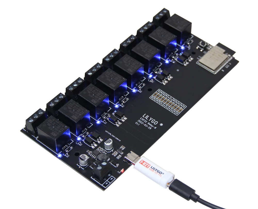
LilyGo T-Relay-8 is an ESP32 WiFi & BLE board equipped with eight 5V relays supporting up to 250V AC or 28V DC, as well as 16-pin GPIO header for expansion.
The board offers a more compact solution than the usual two-board setups with an ESP32 board and a separate 8-relay “Arduino” module, and also integrates optocouplers for improved safety.
LilyGo T-Relay-8 specifications:
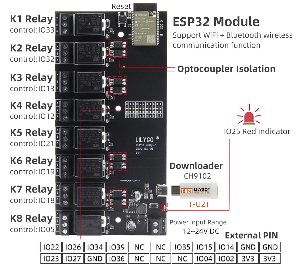
- Wireless module – ESP32-WROVER-E module with ESP32 dual-core processor with 2.4 GHz WiFi 4 and Bluetooth 4.2 connectivity, 4MB flash, 8MB PSRAM
- Relays – 8x HRS4H-S-DC5V 5V relays up to 250VAC/10A or 28VDC/10A with octocoupler isolation, blue LEDs for status
- Expansion – 16-pin header (unpopulated) with GPIOs, 3.3V, and GND
- USB – 1x USB Type-C for programming via optional T-U2T dongle via CH9102 USB to TTL chip
- Misc – Reset button, red user LED
- Power Supply – 12V to 24V via 2-pin terminal block
- Dimensions – 17 x 8.5 x 1.8 cm (the length is 17.5cm if the ESP32 module PCB antenna is taken into account)
The board can be programmed with the Arduino IDE or PlatformIO, and LilyGo provides instructions and code samples to control the relays through the Blynk IoT platform or a web server, as well as a simpler blinky sample of sort turning on and off the relays in sequence. Note that like many of LilyGo boards, T-Relay-8 does not come with an on-board USB-to-TTL chip, and instead, users would need to connect the T-U2T dongle based on the CH9102 chip to program the ESP32 module.
LilyGo T-Relay-8 ESP32 board can be purchased with two unsoldered GPIO headers for $22.38 including shipping, or $27.98 if you don’t have the required T-U2T dongle yet. If you can do with an ESP32 board with just 4 relays instead of 8, the T-Relay is sold for $10.37 plus shipping.

Jean-Luc started CNX Software in 2010 as a part-time endeavor, before quitting his job as a software engineering manager, and starting to write daily news, and reviews full time later in 2011.
Support CNX Software! Donate via cryptocurrencies, become a Patron on Patreon, or purchase goods on Amazon or Aliexpress. We also use affiliate links in articles to earn commissions if you make a purchase after clicking on those links.


It’s not much expensive, and at least you can hope to have working relays when there’s a brand behind. I bought a noname 8-relay board a year ago and they would randomly fail to release, as if the relay core was magnetized. Knocking on them or approaching a magnet would work but that was not practical. I had to order 8 Omron relays with the exact same pinout to replace them!
I don’t know if the programming port can also be used to communicate with the ESP32, because in an enterprise, the last thing you want to do is to leave your relay board accessible over WiFi when it controls your servers!
I did not think about the security aspect of using WiFi to control relays. It might be good if they could make a version with Ethernet. There’s enough space on the board.
Yes that’s what I thought as well. But USB is quite handy in fact, because it eases connection to an existing machine where you can easily control access (HTTP, SSH, etc). Even Ethernet would require either a dedicated LAN or a direct connection to an existing machine (though often it’s not a problem where you have to control 8 servers). In our lab we’re using a good old unkillable ALIX2D3 for this, so Ethernet wouldn’t be a problem! One area where Ethernet becomes better than USB is when you want to control multiple boards. You just have to connect them to a switch and that continues to work fine.
You may want to look at the Shelly pro 4pm. Also esp32 based, ethernet on board, higher quality and din rail mounted with encasing.
Ah indeed, looks like a serious thing for professional deployments. We would have had nowhere to place it in our lab (it requires a din rail) but for plenty of cases it looks way better than the average hacks we can all come up with 🙂
Can someone explain why there are always optocoupler “isolation”, when the isolation to mains is already provided by the relay?
Probably just because they are 12V of 5V relais and the esp io is 3.3V
The relays are 5VDC. I’d just use some random p-fet with flyback diode for this use case. Total cost would be lower and sourcing is a lot easier.
I guess it falls in the “let’s be really safe” area. For example if one relay kills a poor quality fet during release, they don’t want the short voltage spike to reach the ESP32. This can be avoided using resistors and protection diodes, but an optocoupler can become simpler at some point.
The relay can fail it is a mechanical part. Be it too much power and it melts or be it a broken metal part due too just to many switch cycles so mains can be bridged to your 5v actuator. This would render everything broken: your control chip, relays and most likely some fun when you touch it. The optocopler now makes sure there is only an optical connection to the electronics afterwards, no moving parts just light so much less probability to break something
The optocoupler isolation is not to protects from the mains in the relay contacts, its to prevent the relay coil circuit from damaging your microcontroller. I’ve seen relay coils short circuit when their coil insulation melts, this would take out the whole microcontroller if was not optocoupled.
Optoisolators for protection are the least of your worries. In many of the cheap $1 eBay relay modules, the traces for mains power are way way too close (like <1mm) to the low voltage side of the board. Where it should be at least 2.5mm with an air gap in the PCB. See also: "Creepage and clearance"
Those same modules also have undersized traces and screw terminals for the marketed 10A rating, which applies to the relay only.
Would it help if the same reckless/clueless manufacturer added another opto coupler to the flawed board? 😀
Il manque l’alimentation !
Combien vaut le dongle ?
La connectique est inutile si les esp avait un boot OTA, nous sommes en 2022 !
First, as you can see, this site speaks english. Second, connectors would be needed anyway to regain access after a completely messed up OTA update. What they ought to have done however, would be to place the single component in this connector directly onboard.
It sems that there is no varistors to protect the AC switch of the relays. In real AC control use case this can lead to an abnormal stress of the contacts and relays failure.
Where’s the second supply input for the optically isolated part? Or the isolated DC/DC converter on the PCB?
Right. Nowhere, as on nearly every relay board of this kind. The optocouplers are complete BS, because everything is connected to the same supply.
Can you confirm if the T-U2T dongle is optional? The product page says the user needs one to program the relay board.
It’s only optional in the sense that If you don’t plan to upgrade the preinstalled firmware (if any) or already own one, you don’t need to purchase it again.
You will find that you need to buy just one. The USB to Serial chip inside it is needed to program this board.