
SunFounder Pironman is a Raspberry Pi 4 enclosure inspired by Michael Klement’s DIY Raspberry Pi 4 mini server with an OLED display and ICE Tower cooling solution, as well as some improvements such as an aluminum alloy and acrylic enclosure, support for an M.2 SATA SSD, a power button for safe shutdown, an IR receiver, and an RGB LED strip.
The company sent me a Pironman kit without Raspberry Pi 4 for review. I’ll check the package content, go through the assembly, software installation, and testing of the unique features listed above.
Pironman unboxing

Some of the main specifications are listed on the side of the package.

The enclosure comes fully disassembled with the Pironman board, metal and acrylic panels, RGB LED strip, OLED display, heatsink, fan, adapters, flat cables, screws, standoffs, and so on.

The top of the Pironman board (JMS580-V1.8) comes with a JMicron JMS580 USB 3.2 Gen 2 to SATA 6Gb/s bridge, microSD card slot, a USB port for the SSD, a USB port for power, as well as connectors for the GPIO expander, OLED, and a microSD card bridge, as well as some headers to connect the fan, power button, and RGB LED strip.

The bottom side includes the M.2 SATA socket suitable for 2230, 2242, 2260, and 2280 drives, as well as three RGB LEDs, and a 40-pin GPIO header.

There’s also an assembly guide provided in the package. It’s fairly good and helps a lot with the assembly.


You can also access detailed documentation online.
Pironman assembly with Raspberry Pi 4 and M.2 SATA SSD
We’ll need to prepare a Raspberry Pi 4 SBC and a MicroSD card flashed with Raspberry Pi OS, as well as optionally an M.2 SATA SSD.

The first step is to install the standoffs in the mounting holes of the Pironman board as well as insert the OLED display into its connector. Simply lift the black bit, insert the FFC cable into the connector, and push the black bit into place. Make sure the FFC cable is oriented properly as shown in the photo below.

We’ll then stick the display to plate B of the enclosure and install the power switch.

We can now connect the four wires of the power switch to the 5V (red) and GND (black) header, as well as the two green wires to the remaining header next to 5V/GND in no particular order. We’ll do the same for the microSD card bridge, RGB LED, and GPIO expander board.

Everything is a bit tight, but I managed. The most difficult part was installing the FFC cable for the GPIO. The black bit rotates instead of being lifted up, and either the FFC cable is too thick or the connector is too narrow, but it was really hard to close, so I ended up using pliers covered with thick plastic tape to push the black bit into place both on the small adapter board and the main pironman board.

The jumper cables used for the power button, RGB LED, and as we’ll see later the fan, feel a bit loose, so I would not be surprised if they come off if you transport/carry the case to another location. Nevertheless, I had no such problems.

We can now install the Raspberry Pi 4 SBC securing it with more standoffs and a hex key provided with the kit. We can also connect the GPIO and microSD card bridges as shown above.

The next step is to prepare the heatsink by connecting the two supports (note: the orientation is important) and placing the two thermal pads underneath the heatsink.


We can now place the heatsink on top of the Raspberry Pi board and secure it with four screws.

At this point, we can start adding acrylic and metal plates. The fan can be installed on either acrylic plate, but the instructions manual let us attach it to the cover with the GPIO header opening.

We’ll need to install our M.2 SATA SSD before installing the bottom cover.

We’re almost done with the final touch involving the placement of foam pads on the bottom cover (I could have done a better job here).

I noticed the RGB LED strip was not installed properly. I did not clearly understand step 16 which reads “The RGB strip should be pasted to the bottom of metal plate A”. I did not see any dual-sided sticky tape on the LED strip, so I initially placed it in the middle and hoped for the best. But then I noticed I had two black tape left over.

So I removed the top cover and secured the LED strip on both sides of the enclosure.

Finally, I inserted the microSD card and the SSD bridge on one side, and the remaining small acrylic plate to cover the OLED on the other side.

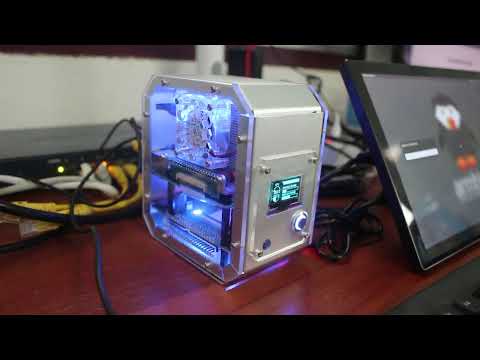
That’s it! It looks nice, and hopefully, we assembled it correctly.
Software installation and features testing
Let’s try it right away by connecting the system to an HDMI display and powering it on. It looks fine and my SATA SSD as detected properly as “NEO Storage”.

I however did something rather stupid above. The red cable comes from the USB adapter, and I did not connect it to the USB-C port on the Pironman system, but instead directly to the Raspberry Pi 4. So initially, after installing the software as shown below, the OLED display would only show the CPU and memory usage for a short time and then show “Power OFF” all the time. So I had a night of good sleep, and in the morning connected the power supply to the USB-C port at the back of the computer.
At this point, we’ll need to follow the online instructions to install the software and drivers to support the OLED, IR receiver, power button, etc…
First, we’ll need to edit /boot/config.txt by adding the two lines below at the end of the file to add support for the power button and IR receiver:
|
1 2 |
dtoverlay=gpio-poweroff,gpio_pin=26,active_low=0 dtoverlay=gpio-ir,gpio_pin=13 |
And then we’ll need to install the pironman Python script:
|
1 2 3 4 |
cd ~ git clone https://github.com/sunfounder/pironman.git cd ~/pironman sudo python3 install.py |
A reboot may be required for everything to work properly, but here’s what it looked like after installing the script.

The OLED shows the IP address, CPU usage, CPU temperature, as well as memory and storage utilization.

We can check the current configuration as follows:
|
1 2 3 4 5 6 7 8 9 10 |
pi@raspberrypi:~ $ pironman -c config file:/home/pi/.config/pironman/config.txt temp_unit = C fan_temp = 50 screen_always_on = False screen_off_time = 60 rgb_switch = True rgb_style = breath rgb_color = 0a1aff rgb_blink_speed = 50 |
The pironman script has several options to change the trigger temperature for the fan, RGB LED colors and modes, and screen behavior. You can also switch between Celcius and Fahrenheit.
|
1 2 3 4 5 6 7 8 9 10 11 12 13 14 15 16 17 18 19 20 21 22 23 24 25 26 27 28 29 |
pi@raspberrypi:~ $ pironman config file: /home/pi/.config/pironman/config.txt Usage: pironman <OPTION> <input> Options: start start pironman service stop stop pironman service restart restart pironman service -h,--help help, show this help -c,--check show all configurations -a,--auto [ on ],enable auto-start at boot [ off ], disable auto-start at boot -u,--unit [ C/F ], set the unit of temperature, C or F (Celsius/Fahrenheit) -f,--fan [ temp ], Temperature at which the fan switches on, in celsius (default 50),in range (30 ~ 80) -al,--always_on [on/off], whether the screen is always on, default False -s,--staty_time [time], screen display duration in second, in second, default 30 -rw,--rgb_sw [on/off], rgb strip switch -rs,--rgb_style rgb strip display style, default: breath, in [breath / leap / flow / raise_up / colorful] -rc,--rgb_color [(HEX)color], set the color of rgb strip, default: 0a1aff -rb,--rgb_speed [speed], rgb blink speed (0 ~ 100, default 50) |
You can also adapt the script since it’s written in Python, and possibly use other scripts since it’s a standard OLED display. Here’s a short demo showing the RGB LED strip and fan in action.
We’ve already seen the RGB LED strip, OLED, and fan working. I could also use the button to turn on the OLED display with a short press and turn off the Raspberry Pi with a 2-second press. I could also turn on the computer by pressing the button again.
Let’s test the IR receiver with LIRC:
|
1 |
$ sudo apt install lirc |
Now that LIRC is installed, we can check if we can receive commands from my TV’s remote control:
|
1 2 3 4 5 6 7 8 9 |
$ mode2 -d /dev/lirc0 Using driver devinput on device /dev/lirc0 Trying device: /dev/lirc0 Using device: /dev/lirc0 code: 0xffffff003096a2007800000103570003 code: 0xffffff0077887900cd0f00019a0f0000 code: 0x28020001cd07000029020001cf070000 code: 0x26020001cd07000028020001cd070000 code: 0x29020001e603000028020001cc070000 |
It looks good. The IR receiver is also working. We should be able to make it work with Kodi and other media centers.
We’ve already seen the SATA drive was recognized, but we have no tested the performance. We’ll install iozone3 for this purpose:
|
1 2 3 4 5 |
wget http://www.iozone.org/src/current/iozone3_494.tgz tar xvf iozone3_494.tgz cd iozone3_494/src/current/ make -j4 linux-arm sudo cp iozone /usr/local/bin/ |
I went to the mount point (/mediap/pi/NEO Storage) before running iozone3 benchmark:
|
1 2 3 4 5 6 7 8 9 10 11 12 13 14 15 16 17 18 19 20 21 22 |
pi@raspberrypi:/media/pi/NEO Storage $ iozone -e -I -a -s 1000M -r 16384k -i 0 -i 1 Iozone: Performance Test of File I/O Version $Revision: 3.494 $ Compiled for 32 bit mode. Build: linux-arm Include fsync in write timing O_DIRECT feature enabled Auto Mode File size set to 1024000 kB Record Size 16384 kB Command line used: iozone -e -I -a -s 1000M -r 16384k -i 0 -i 1 Output is in kBytes/sec Time Resolution = 0.000001 seconds. Processor cache size set to 1024 kBytes. Processor cache line size set to 32 bytes. File stride size set to 17 * record size. random random bkwd record stride kB reclen write rewrite read reread read write read rewrite read fwrite frewrite fread freread 1024000 16384 85561 293438 325212 325262 iozone test complete. |
The read speed (~325MB/s) looks fine over USB 3.0, and the rewrite speed as well, but somehow the write speed (~85MB/s) is on the low side. I tried several times, and the result is the same. I had no such problem when testing the SSD in its USB-C dock in Windows. Note the drive is formatted with the exFAT file system:
|
1 2 |
$ mount | grep NEO /dev/sda1 on /media/pi/NEO Storage type exfat (rw,nosuid,nodev,relatime,uid=1000,gid=1000,fmask=0022,dmask=0022,iocharset=utf8,errors=remount-ro,uhelper=udisks2) |
We can also see the uas driver (for UASP support) is in use for our device:
|
1 2 3 4 5 6 7 8 9 10 11 12 13 14 15 16 |
pi@raspberrypi:/media/pi/NEO Storage $ lsusb Bus 002 Device 002: ID 152d:0580 JMicron Technology Corp. / JMicron USA Technology Corp. USB to ATA/ATAPI Bridge Bus 002 Device 001: ID 1d6b:0003 Linux Foundation 3.0 root hub Bus 001 Device 004: ID 1c4f:0003 SiGma Micro HID controller Bus 001 Device 003: ID 1a2c:0002 China Resource Semico Co., Ltd USB Keykoard Bus 001 Device 002: ID 2109:3431 VIA Labs, Inc. Hub Bus 001 Device 001: ID 1d6b:0002 Linux Foundation 2.0 root hub pi@raspberrypi:/media/pi/NEO Storage $ lsusb -t /: Bus 02.Port 1: Dev 1, Class=root_hub, Driver=xhci_hcd/4p, 5000M |__ Port 2: Dev 2, If 0, Class=Mass Storage, Driver=uas, 5000M /: Bus 01.Port 1: Dev 1, Class=root_hub, Driver=xhci_hcd/1p, 480M |__ Port 1: Dev 2, If 0, Class=Hub, Driver=hub/4p, 480M |__ Port 3: Dev 3, If 0, Class=Human Interface Device, Driver=usbhid, 1.5M |__ Port 3: Dev 3, If 1, Class=Human Interface Device, Driver=usbhid, 1.5M |__ Port 4: Dev 4, If 0, Class=Human Interface Device, Driver=usbhid, 1.5M |
Finally, I wanted to run SBC bench to confirm the cooling ability of the solution:
|
1 2 3 4 5 6 7 |
$ sudo ./sbc-bench.sh -c Average load and/or CPU utilization too high (too much background activity). Waiting... Too busy for benchmarking: 10:23:07 up 44 min, 3 users, load average: 0.52, 0.50, 0.30, cpu: 4% Too busy for benchmarking: 10:23:12 up 44 min, 3 users, load average: 0.48, 0.50, 0.30, cpu: 4% Too busy for benchmarking: 10:23:18 up 44 min, 3 users, load average: 0.44, 0.49, 0.30, cpu: 5% |
But the script refuses to start with the CPU usage even increasing slightly while idle!
 That’s because the Pironman script happens to utilize 4 to 5% of the CPU when the OLED display is on. There’s a 0.5-second sleep in the main loop, but when the display is on there’s also a loop for the display with just a 0.01-second sleep to monitor the button. I had it set to always on to monitor the temperature and CPU usage, but I’ve changed that to default so that the display automatically turns off after a while. I could run the SBC-bench.sh script:
|
1 2 3 4 5 6 7 8 9 10 11 12 13 14 15 16 17 18 19 20 21 |
Checking cpufreq OPP again. Done (20 minutes elapsed). It seems neither throttling nor frequency capping has occured. Memory performance memcpy: 2566.6 MB/s memset: 3399.8 MB/s 7-zip total scores (3 consecutive runs): 5400, single-threaded: 1655 OpenSSL results: type 16 bytes 64 bytes 256 bytes 1024 bytes 8192 bytes 16384 bytes aes-128-cbc 61461.41k 75719.87k 82240.51k 84407.30k 84751.70k 84683.43k aes-128-cbc 61748.61k 76364.71k 82733.91k 84307.29k 84789.93k 84781.74k aes-192-cbc 55657.62k 66900.16k 71660.20k 72982.53k 73187.33k 73405.78k aes-192-cbc 55676.30k 66874.01k 71821.48k 72860.67k 73444.01k 73220.10k aes-256-cbc 50343.01k 59848.85k 63227.48k 64422.57k 64432.81k 64574.81k aes-256-cbc 50459.91k 59570.86k 63347.20k 64332.12k 64476.50k 64623.96k Full results uploaded to http://ix.io/4jVw. Please check the log for anomalies (e.g. swapping or throttling happenend). |
The temperature chart was basically a flat line thanks to the huge heatsink and fan that would turn on from time to time during single-core benchmarks and continuously for the 7-zip multi-core benchmark.

I could also confirm this on the OLED display during the 7-zip test.

I’m not going to do more testing since I’ve already reviewed the ICE Tower with and without the fan, and when overclocking the Raspberry Pi 4 to 2.0 GHz. This type of solution is more than enough, even over-engineered, to cool the Raspberry Pi 4 in most conditions, even overclocked at 2.x GHz.
Final words
The Pironman is quite a nice enclosure for the Raspberry Pi 4. Instructions are detailed, software support is adequate, and it looks really cute. A few things could be improved, for instance, I had trouble installing the FFC cable for the GPIO adapter, and jumper cables may become loose during transport. There’s also a question mark about the low write (but not rewrite) performance with the M.2 SATA drive.
I’d like to thank SunFounder for sending the Pironman case for review. You can purchase the kit reviewed above for $63.99 plus shipping, or purchase a complete kit with a Raspberry Pi 4 2GB RAM and a 32GB MicroSD card for $237.97. The Pironman case can also be purchased from Amazon US.
Note: This review was initially posted on December 30, 2022 as a standard review, and subsequently sponsored to be placed at the top of CNX Software website again on March 21-24, 2023

Jean-Luc started CNX Software in 2010 as a part-time endeavor, before quitting his job as a software engineering manager, and starting to write daily news, and reviews full time later in 2011.
Support CNX Software! Donate via cryptocurrencies, become a Patron on Patreon, or purchase goods on Amazon or Aliexpress. We also use affiliate links in articles to earn commissions if you make a purchase after clicking on those links.


Affordable. Cute. And a bit of Frankenstein.
The price is absolutely nonsense. With the same amount it’s possible to buy an atx case, and not even a low quality one.
only 1 ssd? so no way for a raid or at least rsync?
so they sell the pi4-2gb with 170$ – awesome ! – NOT !
Eh, would be more useful, if I could actually buy a Pi somewhere! They’re out of stock everywhere in Europe, completely unobtainable 😠
I always wanted a Pi Case that came with the Power Supply already integrated in the case, so i didnt need to get a external power supply.
But every case i saw it, has a external power supply
Not even remotely close to being worth it unless you already have a Raspi 4 laying around ….. $174 for Raspi 4 and a SD card is highway robbery
With no availability for over a year and a half the Raspberry Pi platform is dead and may as well be consider EoL
the rgb lighting strip has a sticky back. you just need to remove the brown tape with the green writing.