The BTT Pad 7, or BIGTREETECH Pad 7 in full, is a 7-inch touchscreen display that ships with the CB1 Allwinner H616 system-on-module compatible with Raspberry Pi CM4. The display is mostly designed for 3D printers with its SPI and CAN Bus interfaces, but it can also be used as a standard tablet PC. So today, I’ll switch the CB1 with a Raspberry Pi CM4 Lite module and report my experience doing the conversion and using it as a Raspberry Pi CM4 tablet PC running Raspberry Pi OS, and test it with a 3D printer with Klipper in another post later on.
Installing a Raspberry Pi CM4 (Lite) module in the BTT Pad 7
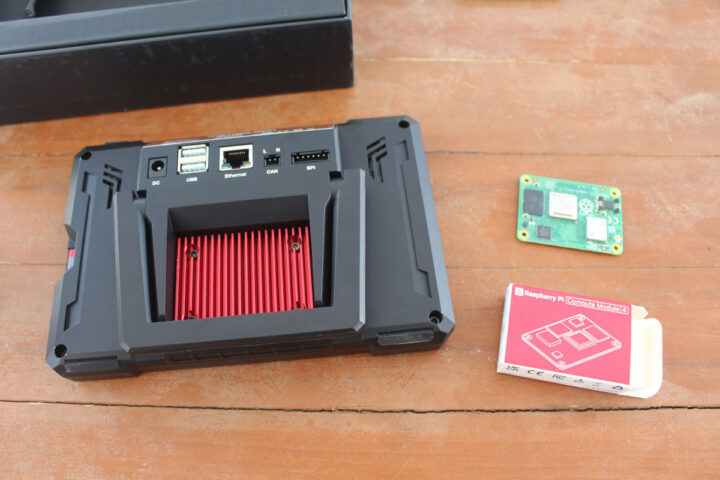
We’ll need the Pad 7, a Raspberry Pi CM4, and a few tools.
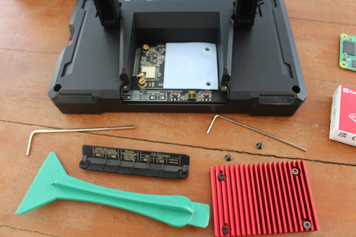
The first step is to remove the red heatsink by loosening four screws with a 2.0mm hex key, as well as the cover with a smaller 1.5mm hex key. I used the ones that came with the Creality Ender-3 S1 Pro 3D printer.
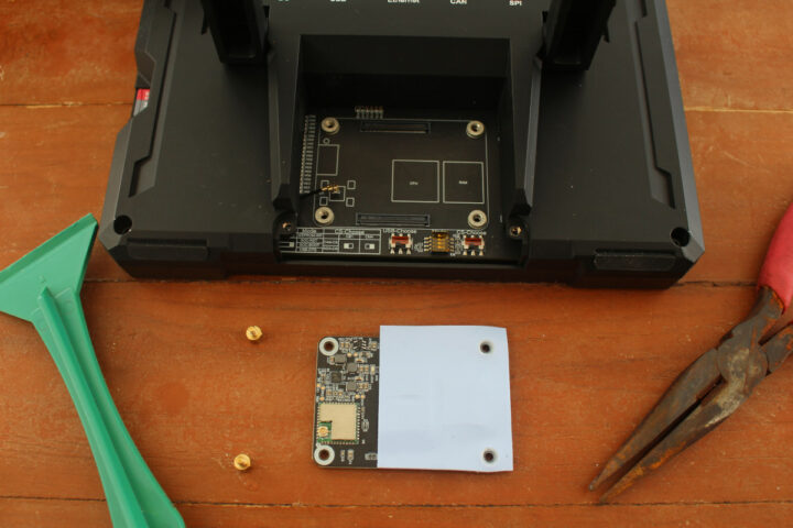
We can now disconnect the Wifi antenna from the CB1 module, remove two short standoffs, and pop out the module with a plastic tool.
The standoff are really small, and not easy to remove especially if you have fat fingers. I did not have an appropriate tool, so I used a pair of (rusty) pliers instead…
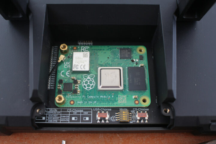
We can now insert the Raspberry Pi CM4 module, connect the antenna cable, and adjust the USB-Choose and CS-Choose switches to the left to configure the Pad 7 for the CM4 module. The user manual is not very detailed, and I initially assumes the CM4 installation would be the same as the CB1 installation, so I tightened the same standoffs in place…
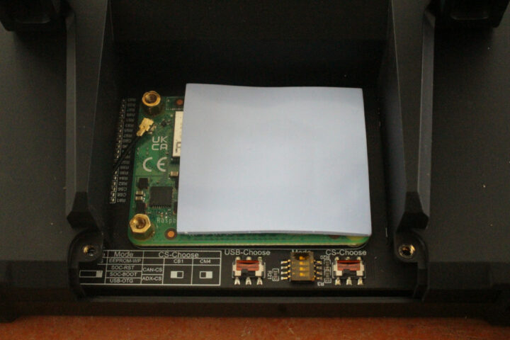
and placed the spare thermal pad on the CM4, before trying to put back the hex screws… But don’t do that, as the CM4 module is thicker than the CB1 module, and you will not be able to tighten all four screws.
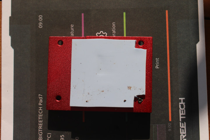
After discussing with BigTreeTech, I found out I had to use what I thought were four spare standoffs and screws, something the user manual does not currently explains at all. So I took out the heatsink, cut out the thermal pad to leave enough space around two of the standoffs. You actually want to place the thermal pad on the heatsink first, rather than the CM4 module, because you may see mine is shifted to the left a bit too much…
As a side note, I like to work outdoors when assembling products because I get some fresh air and the lighting is better for photos, but a downside is there may be some dust that is quite difficult to remove once it ends up on the thermal pad!
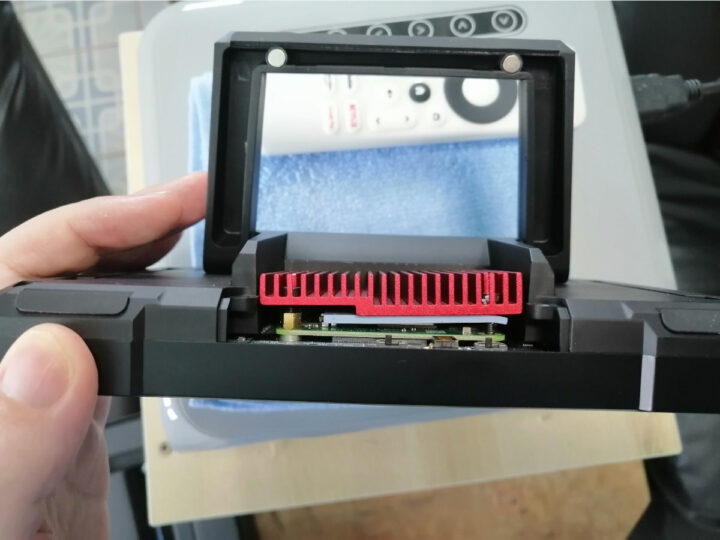
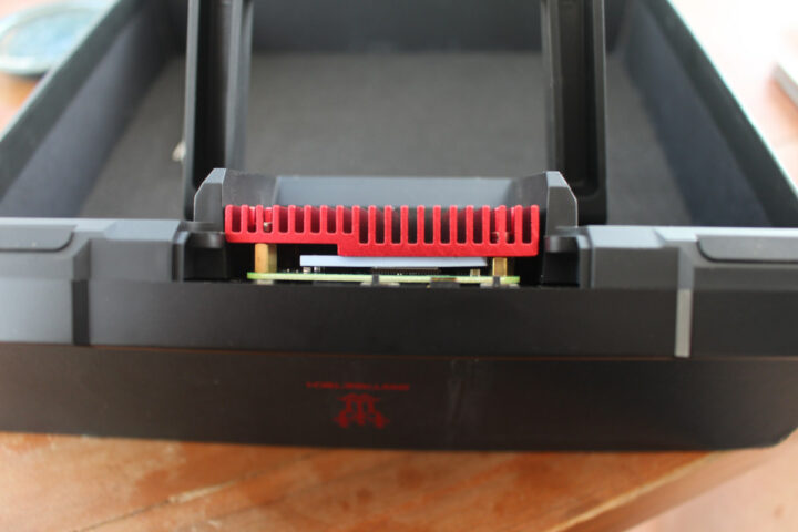
Now we can install the two longer standoffs on the left and the short standoffs on the right, before tightening the four screws to keep the heatsink in place. This looks much better although the heatsink is still slightly inclined, and not perfectly parallel to the PCB. We’ll see if that matters when doing a stress test later on. The final step of the installation is to put back the small cover.
Preparing a microSD card with Raspberry Pi OS
The hardware installation is mostly complete, so we can now prepare a microSD card with the operating system of our choice. The company recommends the latest MainsailOS image for managing Klipper 3D printers, but since it is now our goal at this time, I just went with Raspberry Pi OS Desktop 32-bit using the RPI Imager utility.
Once this is done, you’ll need to change some config files, and the user manual is pretty good for that part. We’ll first need to make some changes for the display backlight which can only be set to maximum brightness because we’re told the backlight IO of the CM4 does not support PWM.
First edit /boot/cmdline.txt and remove “console=serial0,115200“, then edit /boot/config.txt to add the following two lines:
|
1 2 |
dtoverlay=gpio-led dtparam=gpio=14,label=Pad7-lcd,active_low=1 |
We’re also asked to remove the line “enable_uart=1” in /boot/config.txt if it is there, but it was not for me.
We’re still not done editing /boot/config.txt, as we need to configure the HDMI resolution (1024×600):
|
1 2 3 4 |
hdmi_group=2 hdmi_mode=87 hdmi_cvt 1024 600 60 6 0 0 0 hdmi_drive=1 |
and enable USB host:
|
1 |
dtoverlay=dwc2,dr_mode=host |
That’s all I did myself, but if you’re going to connect the Pad 7 to a 3D printer, you’ll also want to setup SPI to CAN bus in /boot/config.txt:
|
1 2 |
dtparam=spi=on dtoverlay=mcp2515-can0,oscillator=12000000,interrupt=24,spimaxfrequency=10000000 |
Edit /etc/network/interfaces.d/can0 with settings that are consistent with Klipper, for example:
|
1 2 3 4 |
allow-hotplug can0 iface can0 can static bitrate 1000000 up ifconfig $IFACE txqueuelen 1024 |
Finally, if you’re going to use the provided ADXL345 IMU module, you’ll need to add the following configuration to the printer.cfg file:
|
1 2 3 4 5 6 |
[mcu CM4] serial: /tmp/klipper_host_mcu [adxl345] cs_pin: CM4:None spi_bus: spidev0.1 axes_map: z,y,-x # Modify according to the actual orientation of the ADXL345 installed on the printer. |
Now save everything, and take out the microSD card to insert it into the BTT Pad 7. But before that, you’ll need to remove the microSD card with the OS for the CB1, and it did not come out easily for me. I could not take it out with my finger, and I had to use a tool and exert a bit more force than I’m comfortable with in terms of potentially damaging the card or tablet. I told BIGTREETECH about the issue, and they are aware of it:
Yea. We have also noticed this problem, which seems to be a small probability and will only occur in our first batches, and we have optimized this problem in subsequent batches.
So the good news is that it happened to me and potentially other reviews or beta testers, but should not happen to customers since the Pad 7 is still at the pre-order stage.
Configuring and testing Raspberry Pi OS
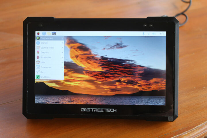
Anyway, I inserted the microSD card with Raspberry Pi OS in the BTT Pad 7, connected the power supply, and within a few seconds, I got to the desktop interface with the touchscreen also working.
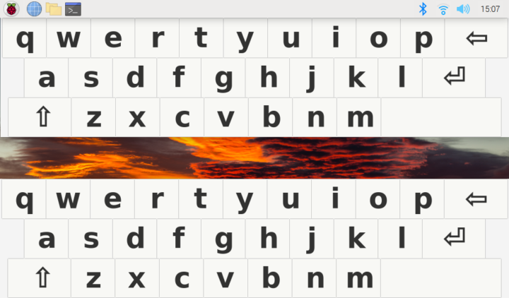
If you’re not using a mechanical keyboard or air mouse, you’ll probably want to install an onscreen keyboard such as the “matchbox” keyboard:
|
1 |
sudo apt install matchbox-keyboard |
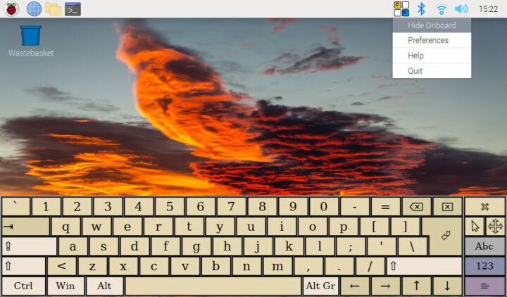
But it turns out it’s not very good in the latest version of Raspberry Pi and can’t be closed easily for example, at least not without changing the layout file. But I found a better option with the “onboard” keyboard. The at-spi2-core package is optional, but required for some features:
|
1 |
sudo apt install onboard at-spi2-core |
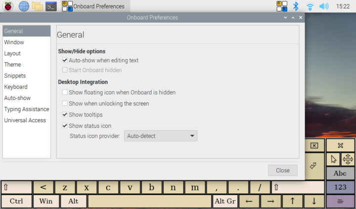
It’s smaller, but customizable and easier to use with an icon in the notification bar to show/hide it, and access its preferences.
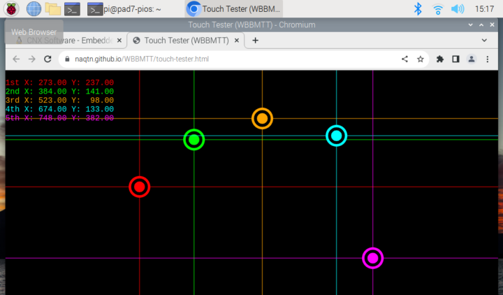
I also had to find a way to test multi-touch in Linux. The recommended program in Ubuntu is PyMT, but it’s old, and won’t install on Raspberry Pi OS. evtest is a command line option, but it will spew data continuously, so I eventually ended up using an HTML5-based touch tester website in Chromium.
You can watch a short demo showcasing touchscreen interface support on the BTT Pad 7 with Raspberry Pi CM4 while browsing the web, using the Touch Tester above, as well as the Onboard keyboard.
I also tested the other features of the Pad 7:
- USB port – Fine. All three USB 2.0 ports have been tested with RF dongles for a mouse and keyboard
- Built-in speaker – OK
- Audio jack – OK tested with a pair of USB-powered speakers
- Ethernet – Works fine at Gigabit Ethernet speed, tested at 936 Mbps with iperf3.
- WiFi – It works, but the signal looks weaker than expected at about 6 meters from a dual-band router and a few walls, and the system would only detect the 2.4GHz SSID. If placed in the same room, the 5GHz SSID was also detected, the WiFi signal was strong, and the connection stable.
- Power button – It will turn on and off the system, but it will not allow for a soft shutdown, it’s just a button that physically turns on and off the power.
- Volume buttons – The volume buttons are working to control the built-in speaker volume, but note it will not show up in the system’s volume. It’s a hardware thing like the power button.
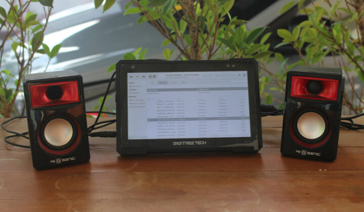
Finally, I’ve run sbc-bench.sh script to check if cooling was working efficiently, or at least well enough to avoid thermal throttling:
|
1 2 3 4 5 6 7 8 9 10 11 12 13 14 15 16 17 18 19 20 21 22 23 24 25 26 27 28 29 30 31 32 33 34 35 36 37 38 39 40 41 42 43 44 45 46 47 48 49 50 51 52 53 54 55 56 57 58 59 60 61 62 63 64 65 66 67 68 69 70 71 72 73 74 75 76 77 78 79 80 81 82 83 84 85 86 87 88 89 90 91 92 93 94 95 96 97 98 99 100 101 102 103 104 105 106 107 108 109 110 111 112 113 114 115 116 117 118 119 120 121 122 123 124 125 126 127 128 129 |
pi@pad7-pios:~ $ ./sbc-bench.sh -r Warning: for useable results this tool needs to be run as root pi@pad7-pios:~ $ sudo ./sbc-bench.sh -r Starting to examine hardware/software for review purposes... Average load and/or CPU utilization too high (too much background activity). Waiting... Too busy for benchmarking: 10:19:30 up 11 min, 4 users, load average: 0.52, 1.12, 0.86, cpu: 26% Too busy for benchmarking: 10:19:35 up 11 min, 4 users, load average: 0.48, 1.10, 0.85, cpu: 5% Too busy for benchmarking: 10:19:40 up 11 min, 4 users, load average: 0.52, 1.10, 0.85, cpu: 5% Too busy for benchmarking: 10:19:45 up 11 min, 4 users, load average: 0.48, 1.08, 0.85, cpu: 15% Too busy for benchmarking: 10:19:50 up 11 min, 4 users, load average: 0.44, 1.06, 0.84, cpu: 0% Too busy for benchmarking: 10:19:55 up 11 min, 4 users, load average: 0.48, 1.06, 0.84, cpu: 0% Too busy for benchmarking: 10:20:00 up 11 min, 4 users, load average: 0.44, 1.04, 0.84, cpu: 1% Too busy for benchmarking: 10:20:06 up 11 min, 4 users, load average: 0.41, 1.02, 0.83, cpu: 0% Too busy for benchmarking: 10:20:11 up 12 min, 4 users, load average: 0.38, 1.01, 0.83, cpu: 0% Too busy for benchmarking: 10:20:16 up 12 min, 4 users, load average: 0.35, 0.99, 0.82, cpu: 0% sbc-bench v0.9.41 Installing needed tools: apt -f -qq -y install lm-sensors sysstat lshw stress-ng smartmontools mmc-utils, tinymembench, ramlat, mhz (can't build cpuminer) Done. Checking cpufreq OPP. Done. Executing tinymembench. Done. Executing RAM latency tester. Done. Executing OpenSSL benchmark. Done. Executing 7-zip benchmark. Done. Throttling test: heating up the device, 5 more minutes to wait. Done. Checking cpufreq OPP again. Done (15 minutes elapsed). Results validation: * Measured clockspeed not lower than advertised max CPU clockspeed * No swapping * Background activity (%system) OK * No throttling Full results uploaded to http://ix.io/4wj8 # Raspberry Pi Compute Module 4 Rev 1.1 Tested with sbc-bench v0.9.41 on Sun, 21 May 2023 10:36:27 +0700. Full info: [http://ix.io/4wj8](http://ix.io/4wj8) ### General information: BCM2711, Kernel: aarch64, Userland: armhf CPU sysfs topology (clusters, cpufreq members, clockspeeds) cpufreq min max CPU cluster policy speed speed core type 0 0 0 600 1500 Cortex-A72 / r0p3 1 0 0 600 1500 Cortex-A72 / r0p3 2 0 0 600 1500 Cortex-A72 / r0p3 3 0 0 600 1500 Cortex-A72 / r0p3 3794 KB available RAM ### Governors/policies (performance vs. idle consumption): Original governor settings: cpufreq-policy0: ondemand / 1500 MHz (conservative ondemand userspace powersave performance schedutil / 600 700 800 900 1000 1100 1200 1300 1400 1500) Tuned governor settings: cpufreq-policy0: performance / 1500 MHz ### Clockspeeds (idle vs. heated up): Before at 50.1°C: cpu0 (Cortex-A72): OPP: 1500, ThreadX: 1500, Measured: 1498 After at 68.7°C: cpu0 (Cortex-A72): OPP: 1500, ThreadX: 1500, Measured: 1498 ### Performance baseline * memcpy: 2531.8 MB/s, memchr: 1250.0 MB/s, memset: 3254.2 MB/s * 16M latency: 161.9 163.1 162.3 163.5 162.2 163.3 195.5 198.0 * 128M latency: 189.9 180.4 182.1 180.1 184.3 186.6 204.4 221.2 * 7-zip MIPS (3 consecutive runs): 5690, 5730, 5751 (5720 avg), single-threaded: 1648 * `aes-256-cbc 50494.15k 59840.38k 63452.50k 64302.76k 64419.16k 64716.80k` * `aes-256-cbc 50645.94k 59683.14k 63472.73k 64389.12k 64697.69k 64673.11k` ### Storage devices: * 29.1GB "SD32G" UHS DDR50 SD card as /dev/mmcblk0: date 09/2022, manfid/oemid: 0x0000b1/0x4847, hw/fw rev: 0x6/0x1 ### Swap configuration: * /var/swap on /dev/mmcblk0p2: 100.0M (0K used) on ultra slow SD card storage ### Software versions: * Raspbian GNU/Linux 11 (bullseye) * Build scripts: http://archive.raspberrypi.org/debian/ bullseye main * Compiler: /usr/bin/gcc (Raspbian 10.2.1-6+rpi1) 10.2.1 20210110 / arm-linux-gnueabihf * OpenSSL 1.1.1n, built on 15 Mar 2022 * ThreadX: 82f3750a65fadae9a38077e3c2e217ad158c8d54 / Mar 17 2023 10:50:39 ### Kernel info: * `/proc/cmdline: coherent_pool=1M 8250.nr_uarts=0 snd_bcm2835.enable_headphones=0 snd_bcm2835.enable_hdmi=1 snd_bcm2835.enable_hdmi=0 video=HDMI-A-1:1024x600M@60 smsc95xx.macaddr=E4:5F:01:E4:B8:E5 vc_mem.mem_base=0x3ec00000 vc_mem.mem_size=0x40000000 console=tty1 root=PARTUUID=47e4a404-02 rootfstype=ext4 fsck.repair=yes rootwait quiet splash plymouth.ignore-serial-consoles` * Vulnerability Spec store bypass: Vulnerable * Vulnerability Spectre v1: Mitigation; __user pointer sanitization * Vulnerability Spectre v2: Vulnerable * Kernel 6.1.21-v8+ / CONFIG_HZ=250 Kernel 6.1.21 is not latest 6.1.29 LTS that was released on 2023-05-17. See https://endoflife.date/linux for details. Perhaps some kernel bugs have been fixed in the meantime and maybe vulnerabilities as well. All known settings adjusted for performance. Device now ready for benchmarking. Once finished stop with [ctrl]-[c] to get info about throttling, frequency cap and too high background activity all potentially invalidating benchmark scores. All changes with storage and PCIe devices as well as suspicious dmesg contents will be reported too. Time fake/real load %cpu %sys %usr %nice %io %irq Temp VCore 10:36:28: 1500/1500MHz 3.42 46% 4% 40% 0% 0% 0% 64.3°C 0.8700V 10:37:28: 1500/1500MHz 1.26 0% 0% 0% 0% 0% 0% 60.4°C 0.8700V 10:38:28: 1500/1500MHz 0.54 0% 0% 0% 0% 0% 0% 59.4°C 0.8700V 10:39:28: 1500/1500MHz 0.20 0% 0% 0% 0% 0% 0% 56.5°C 0.8700V |
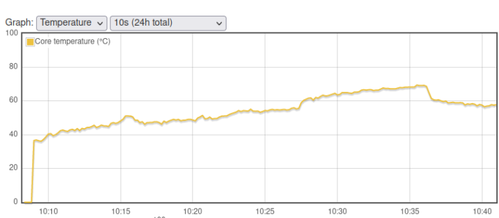
There are no complaints except for the swap on the microSD card… The temperature chart from rpi-monitor confirms the CPU temperature never exceeded 70°C.
The measurements were done in a room with an ambient temperature of around 28°C. The red heatsink feels quite hot to the touch, but that means it’s doing its job.
Conclusion
BIGTREETECH says the Pad 7 is “Not only a Klipper Pad”, but also a mini-computer. So I tested that by using it as a tablet PC fitted with a Raspberry Pi CM4 Lite system-on-module. It took some effort to install the CM4 module and configure Raspberry Pi OS to my needs, but eventually, everything works fine to my expectations including all features and the cooling solution is adequate. The main downsides are the relatively weak WiFi signal and the lack of a soft power button, which would be convenient, but you can also use the menu to turn it off if needed.
The company does not sell a barebone version of the BTT Pad 7 at this time, and instead, it ships with the BIGTREETECH CB1 module for $129.00 on BIQU website. A barebone model would probably cost around $99.90 if they offer one in the future. I’ll soon switch from the Raspberry Pi CM4 back to the CB1 module to connect the BTT Pad 7 to a 3D printer and use it as a Klipper pad together with the provided IMU. Continue reading: “Review of BIGTREETECH Pad 7 Klipper pad with Creality Ender-3 Pro S1 3D printer“

Jean-Luc started CNX Software in 2010 as a part-time endeavor, before quitting his job as a software engineering manager, and starting to write daily news, and reviews full time later in 2011.
Support CNX Software! Donate via cryptocurrencies, become a Patron on Patreon, or purchase goods on Amazon or Aliexpress. We also use affiliate links in articles to earn commissions if you make a purchase after clicking on those links.





Hello Jean-Luc, did you have a chance to see if CAN interface works with rpi cm4?
Thank you.
CIO
I don’t have any hardware to connect to it. But I’ve just tried to enable it by modifying the config.txt file and creating the /etc/network/interfaces.d/can0 file as explained in the user manual and the post above. But after a reboot, nothing shows up in dmesg:
Checking the SPI devices does not show any “net” folders either:
But I’m not entirely sure how to test it.
I should have done a case-insensitive grep:
Love the soundtrack on that video! 🙂
Hi, I am trying doing what you decribed here above installing raspiOS on the CM4 installed on my pad7. However I do not succeed and the screen remains black. No PiOs loading or detected. I try to connect using SSH but it is not working either. Do you have any suggestions that can help me getting the pad7 working with my M4 and RaspiOS? Thanks in beforehand
Does the CM4 still work with another carrier board?
I can’t remember if it is possible on the Pad 7, but using a USB to serial debug board to monitor the boot process might help.
It might also be a connection issue, try to remove the module and reinsert it.
Does cm5 work?