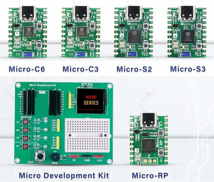
SB Components is back with yet another crowdfunding campaign this time with the Microflex MCUs USB development boards all with the same tiny form factor and offered with a choice of five microcontrollers namely Raspberry Pi RP2040, ESP32-S3, ESP32-S2, ESP32-C3, or ESP32-C6.
Microflex MCUs share the same layout with a USB-C port for power and programming, a built-in RGB LED, two buttons for Boot and Reset/User, and two rows of 10-pin with through and castellated holes to access the GPIOs and power signals such as 5V, 3.3V, and GND.
But they differ in terms of the processor used, wireless features, and available I/Os as shown in the table below which sadly lacks any information about the flash and eventual PSRAM…
| Model | Micro-S3 | Micro-S2 | Micro-C3 | Micro-C6 | Micro-RP |
|---|---|---|---|---|---|
| SoC | ESP32-S3 | ESP32-S2 | ESP32-C3 | ESP32-C6 | RP2040 |
| Core(s) | Dual-core LX7 @ 240 MHz with vector extension | Single-core LX7 @ 240 MHz | Single-core RISC-V @ 160 MHz | Single-core RISC-V @ 160 MHz | Dual-core Cortex-M0+ @ 133 MHz |
| Memory | 512KB SRAM | 320KB SRAM | 400KB SRAM | 512KB HP and 16KB LP SRAM | 264KB SRAM |
| Storage | 384KB ROM | 128KB ROM | 384KB ROM | 320KB ROM | 16KB ROM |
| WiFi | WiFi 4 | WiFi 4 | WiFi 4 | 2.4 GHz WiFi 6 | N/A |
| Bluetooth | 5.0 | N/A | 5.0 | 5.3 | N/A |
| 802.15.4 radio | N/A | N/A | N/A | Yes for Zigbee 3.0 and Thread 1.3 support | N/A |
| Digital I/O | SPI, I2C, I2S, UART | SPI, I2C, I2S, UART | SPI, I2C, I2S, UART | SPI, I2C, I2S, UART | SPI, I2C, UART |
| Analog I/O | 12-bit ADC | 13-bit ADC and 8-bit DAC | 12-bit ADC | 12-bit ADC | 12-bit ADC |
| Kickstarter price | $9 | $9 | $8 | $9 | $7 |
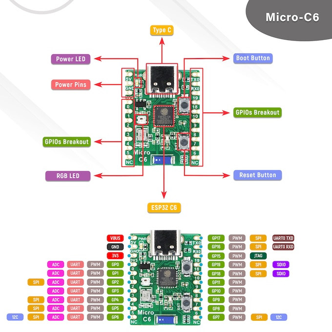
The illustration below includes some more details for the Micro-C6 with the main components, ports, and a pinout diagram.
Programming the firmware for the ESP32-series can be done through the ESP-IDF framework, MicroPython, or the Arduino IDE, and the Raspberry Pi RP2040 (Micro-RP) board can be programmed with the official Raspberry Pi MicroPython and C/C++ SDKs, the Arduino IDE, etc…
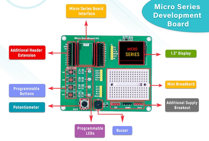
SB Components also designed the Micro Series development board that can take the modules through the two 10-pin headers in order to quickly evaluate the solution with the built-in display, breadboard, buttons, etc…
Key features:
- 170-pin breadboard onboard
- 1.3-inch LCD
- 4 Programmable LEDs and buttons
- Onboard buzzer, potentiometer
- Additional Power supply Breakout pins (3.3V & 5V)
- Male/Female GPIO header to access the I/Os of a Microflex MCU board when plugged into the dev board.
As usual, SB Components is a complete failure when it comes to providing clear information and example programs during the crowdfunding campaign, but they do usually provide some documentation with sample codes after the campaign is finished. The accompanying video shows some demos whose code might be eventually released.
SB Components has launched the Microflex MCU series on Kickstarter and raised a little over $3,500 so far. There’s plenty of competition for this type of board and the main value proposition is probably that it’s easy to test different ESP32 MCUs and the RP2040 with a single devkit. Prices range from $7 to $9 for the Microflex MCU boards, and a kit with the Micro Development Kit and the 5 boards goes for $57. Shipping adds 5 GBP to the UK, and about $10 to the rest of the world with deliveries expected to start by April 2024.

Jean-Luc started CNX Software in 2010 as a part-time endeavor, before quitting his job as a software engineering manager, and starting to write daily news, and reviews full time later in 2011.
Support CNX Software! Donate via cryptocurrencies, become a Patron on Patreon, or purchase goods on Amazon or Aliexpress


I like the idea. Both the availability of different MCUs for the same board pinout, and the small dev board that makes it easy to use. In spirit it reminds me about this kit I started with almost 40 years ago and that I loved for its versatility and its manual: https://hackaday.com/2019/02/10/there-are-200-electronic-kits-in-that-box/
I think that putting multiple components on the base board (buttons, LEDs, potentiometer, speaker etc) is exactly what eases experimentation. You constantly think about the functions you’ll assign them instead of thinking about whether or not to add another component. And just getting used to visually have your LEDs and buttons always at the same place helps to think in terms of human interface.
I’ve just noticed I did not include the dimensions in the post: 26.43 x 20.61 mm