I’ve just received a review sample of the M5Stack Tab5 ESP32-P4 IoT development kit, which looks like a small tablet with a 5-inch touchscreen display, a 2MP front-facing camera, an ESP32-C6 WiFi 6, Bluetooth, and 802.15.4 wireless module, and various expansion interfaces.
Today, I’ll go through an unboxing, a (partial) teardown, and have a quick try with the default firmware and GUI, before checking out how to program the device in the second part of the review.
M5Stack Tab5 unboxing
I received the Tab5 in its retail package along with an M5Stack-branded transparent sticky tape roll. Not sure why, but thanks M5Stack, sticky tape is always useful, so appreciated!

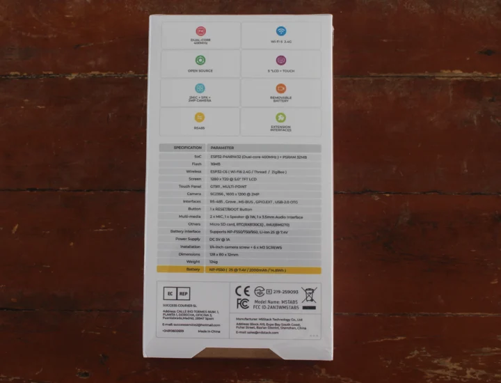
The bottom side of the package has all the key features and specifications that we already covered in our article about the Tab5.
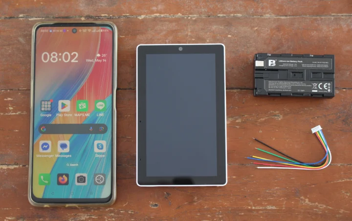
The package contains the Tab5 itself, a 2,000mAh/14.8Wh battery, and a cable with six wires for the ExtPort2 expansion port with I2C and RS485 signals
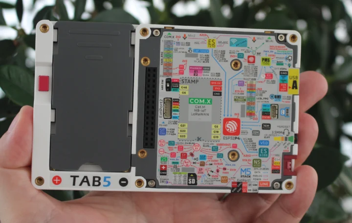
The bottom side has a cover for the battery compartment, a block diagram, two expansion headers (M-Bus 2.54mm pitch header, ExtPort2 connector with RS485 resistor switch), and mounting threads.
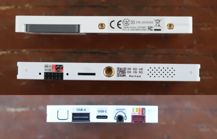
If we look at the M5Stack Tab5 at an angle, we’ll find the power button, USB-A output port, USB-C input port, a 3.5mm audio headset, and Port A GPIO header on one side. The ExPort1 connector (GPIO + 6 to 24V DC input), a microSD card slot, a mounting thread for a camera tripod (or similar accessories), and holes for the built-in speaker can be found on the other side.
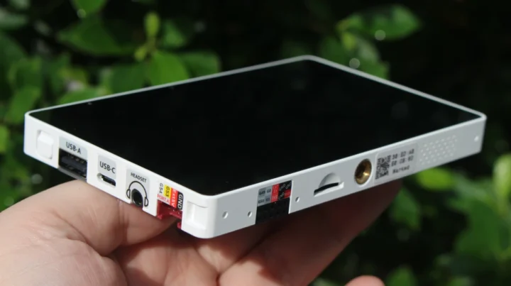
The top side includes two connectors for external antennas, which are not included by default, since there’s already an internal 3D antenna.
M5Stack Tab5 teardown
Let’s start the teardown by remove the battery compartment cover and removed four hex screws to remove the cover to the right. Note that the sticker extends to the Export1 connector, so you have to carefully remove the cover to avoid tearing the sticker.
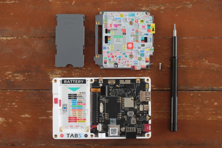
Without the battery, we can see the pinout of the M-Bus connector and the location of the SC2356 camera module. The top of the board features an ESP32-C6-MINI-1U module connector to both a 3D antenna and external antenna connectors (selectable by software), a microSD card slot, and an footprint for an M5Stamp Cat M/NB-IoT ot LoRaWAN module.

I disconnected the battery cable and the camera FPC cable (on the left), but two wires are soldered to the mainboard, and I didn’t want to mess with it since I hadn’t even turned on the device. I just had a quick peek inside, seeing a flexible PCB with a GT911 touchscreen controller, and not much else.
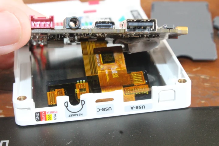
Using the firmware on the ESP32-P4 IoT development kit
Let’s try the Tab5 by connecting the battery.
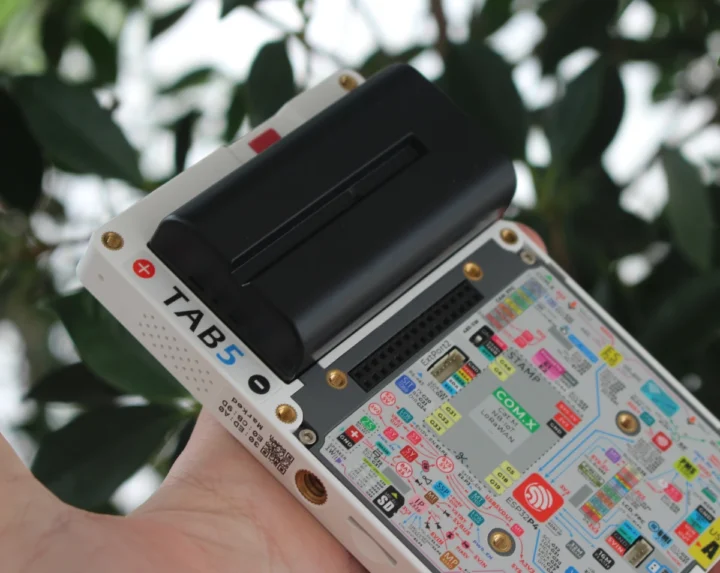
The system will automatically boot to the user interface. At first glance, that’s a bit messy, but it’s really useful to test all low-level features of the tablet.
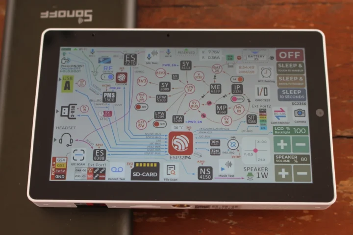
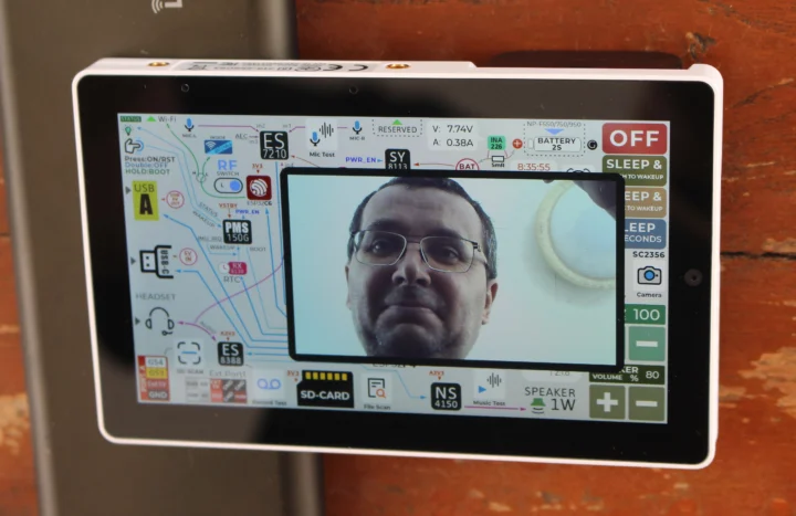
For instance, we can tap on the camera icon on the left, and a window will show up with the live feed. Double-tapping on the camera output will bring it to full screen. While the ESP32-P4 is quite powerful for a microcontroller, the frame rate is low in full-screen mode, something like 1 or 2 FPS.
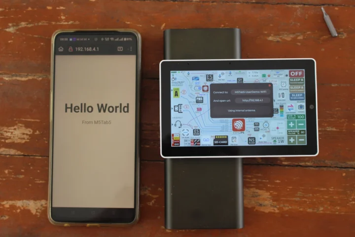
The RF switch allows the user to switch between the internal and external WiFi antenna and bring up a test open SSID (M5Tab5-UserDemo-WiFi) and IP address for the user to try. I went with the internal antenna and typed the IP address in Firefox on my Android smartphone to load a Hello World webpage.
I quickly tried or browsed other functions to adjust brightness (and see real-time power consumption increase or decrease), adjust the volume, play music, record a 3-second sample of my voice and play it back, change the level of GPIO pins, scan I2C devices, send a string over RS485, turn on/off USB port, and test various wake/sleep modes (touch-to-wake, sleep-to-wake, etc…).
The default firmware is great to have a quick look at the features of the Tab5 and the capabilities of the ESP32-P4 RISC-V microcontroller. The source code is available on GitHub, so it can also serve as a starting point to develop your own firmware.
Since the battery is optional, and M5Stack also sells the Tab5 without a battery, I tested the devkit with USB power after removing the battery. When I connected the Tab5 directly to one of the USB ports of my power extension, the device would enter an infinite boot loop. Changing to a USB power adapter fixed the issue, and the Tab5 works fine without its battery.

Besides the demo firmware, I don’t think there are any useful applications designed for the M5Stack Tab5 just yet, so in the second part of the review, I plan to report my experience building the firmware from source and modifying it, so readers can get a better feel of the developer experience.
I’d like to thank M5Stack for sending the Tab5 ESP32-P5 IoT development kit for review. The company sells it for $55 or $60 on AliExpress and its online store, with the price depending on whether you need the battery. Note that stocks are limited, but a new batch is scheduled for next month, so you’d have to wait a few weeks in case the kit runs out of stock.

Jean-Luc started CNX Software in 2010 as a part-time endeavor, before quitting his job as a software engineering manager, and starting to write daily news, and reviews full time later in 2011.
Support CNX Software! Donate via cryptocurrencies, become a Patron on Patreon, or purchase goods on Amazon or Aliexpress




Great writeup. If you interact with the M5Stack org, please tell them to get busy on 915Mhz Lora modules.