Xilinx Zynq SoCs are probably the most well-known FPGAs with ARM cores, as their Cortex A9/A53 cores can run Linux, but they are not the only ones. Microsemi launched SmartFusion2 SoC comprised of FPGA fabric and an Arm Cortex-M3 core in 2013, as well as a $300 development kit.
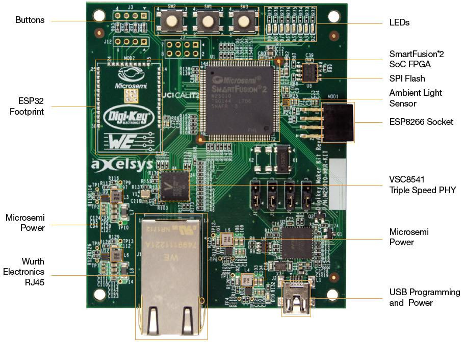
The company has now partnered with Digikey to launch SmartFusion2 Maker Board, a low-cost evaluation platform for the SoC that comes with Gigabit Ethernet, a USB port, a connector for ESP8266 module, PCB footprint for ESP32 module, among other features like a light sensor, LEDs, and buttons.
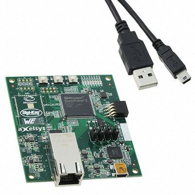
SmartFusion2 maker board (M2S010-MKR-KIT) main features & specifications:
- SoC – Microsemi SmartFusion2 M2S010 SoC with:
- Arm Cortex-M3 @ 166 MHz, 6oKB+80KB eSRAM, 256KB eNVM
- FPGA with 12,084 logic element, 400 Kbits RAM
- Storage – 16 Mbit SPI Flash
- Connectivity
- Gigabit Ethernet via VSC8541 PHY, RJ45 connector
- Connector for ESP8266 (Sparkfun WRL-13678 – not included)
- Laid out footprint for ESP32 (DFRobot ESP-WROOM-32 – not included)
- USB (for programming/debugging) – USB integrated FlashPro5 programming hardware; USB port for UART communications
- Sensor – Ambient light sensor
- Misc – 8x user LEDs, 3x buttons including two user pushbuttons, 50 MHz clock source
- Power Supply – 5V via mini USB port; LX7167A PMIC
- Dimensions – N/A
The SmartFusion2 maker board can be used with Microsemi’s Libero SoC v11.8 or greater with a (Free) Silver license to program the FPGA fabric, and SoftConsole Eclipse based IDE to code the Arm Cortex M3 core in C/C++. You’ll find documentation on eewiki’s getting started guide.
The board – also known as M2S010-MKR-KIT – can be purchased for $33.75 through Digikey with close to 2,000 unit in stock at the time of writing. There may also be further information on the product page on Microsemi website.

Jean-Luc started CNX Software in 2010 as a part-time endeavor, before quitting his job as a software engineering manager, and starting to write daily news, and reviews full time later in 2011.
Support CNX Software! Donate via cryptocurrencies, become a Patron on Patreon, or purchase goods on Amazon or Aliexpress

First impressions of that board: Why did they put the antenna for the ESP32 right over the center of the board? The antenna portion should either hang off the edge of the board or should have no ground/power planes under it. From it’s placement, that’s extremely unlikely. There doesn’t seem to be anywhere near enough decoupling caps for either the ESP32 nor the ESP8266. Both of those boards are known to have huge power spikes and need large amounts of decoupling caps.
I’ll channel tkaiser here and say “power over micro-USB? No thank you.”
@willmore
This should hopefully draw a lot less power than the average Single Board Computer.
@Malem
Clearly, but it’s not the bulk power draw that’s the problem. It’s the irregularity of the power draw in the ESP devices due to the bursty nature of WiFi transmissions. Switching regulators rarely have the dynamic handling properites to keep up with that unless specifically designed to.
Not with that FPGA, it won’t… X-D
@willmore
Yeah, I asked the same sorts of questions when I looked at this thing. Cute, but it’s got some design fails as you’ve rightly observed.
And the SmartFusion 2’s “okay” but for that M3 hard-macro, you could’ve had more gate logic and been a bit more flexible with a RISC-V CPU on the thing with the ability to select how much of the FPGA fabric you’re sacrificing for RAM/ROM, etc.
TL;DR version…
– USB Micro Power on an FPGA? Gonna need a bigger NOPE.
– M3 Macro that’s no better/faster than a VexRiscv or Rocket for cells that you could have used elsewhere? Nope.
– Oopses on the power rails for ESP32 and ESP8266? Gonna need a bigger NOPE.
@Nobody of Import
TL;DR actually means: Too hard to read more than one paragraph, didn’t bother to educate myself by reading the whole article before talking trash about a product.
USB 2.0 = 5V@500mA.. Or.. I*A = 2.5 watts.
USB 3.0 = 5V@900mA.. Or.. I*A = 4.5 watts.
SmartFusion 2 supply in worst-case process 1.3V@369mA.. or <.5 watts.
SmartFusion 2 programming currents: Maximum of 388mA.. or.. Just a snot-hair more than .5 watts.
What are they teaching kids these days?
@Grumpy Old Coot
The power consumption never bothered me, it’s simply the current spikes the ESP chips can draw. They can easily peak at >0.5A. So, you have a choice on USB: You can use a linear regulator and worry about hitting the current limit, you can use a switching regulator and worry about transient response, or you can just throw a big cap on it.
If they chose #1, then I think they made a bad desision and they’ll be pushing over the current limits of the micro-USB connector. If they choose #2, a competent EE should be able to make it work if they paid close attention. They didn’t choose #3 as there’s no huge electrolytic cap on the board. It could be that one of those SMD devices is a very expensive MLC with enough capacity and a low enough ESR, but I’m not inclined to be charatable when looking at the rest of the board.
@willmore
There’s no Micro USB here, it’s the older Mini USB connector. I tried to look up specs for maximum current ratings at 5V but did only find this here (ecn1-usb20-miniB-revd.pdf):
‘Contact Current Rating: The object of this test procedure is to detail a standard method to assess the current carrying capacity of mated USB connector contacts.
1.5(1 for “mini-B” connector) A at 250 V AC minimum when measured at an ambient temperature of 25° C. With power applied to the contacts, the ∆ T must not exceed +30° C at any point in the USB connector under test.’
@tkaiser
The current rating for all USB 2.0 connectors was .5A unless it was designed for the BC spec and then that’s a different animal.
That Microsemi SmartFusion2 M2S010 SoC on the board is in a 20mmx20mm 0.5mm pitch TQFP144 flat-pack, the only prototype-friendly package type they offer. But they do offer it! That makes this part attractive.
Unfortunately at 84 GPIO pins and 1 lane, the TQFP144 package breaks out the least number of pins compared to the 3 other (harder to work with) offered package types for the M2S010 part.
I think they went with the M3 because the part and tool-chain are well known. However Micrsemi does offer a 32 bit soft RISC-V processor based on the Coreplex E31 architecture. But I think you will have to call them and get the details (it may be big for this FPGA). See here:
https://www.microsemi.com/products/fpga-soc/design-resources/ip-cores
Their (seemingly Win/Linux compatible) Libero SoC Design Suite in the long term Free version is limited to 5K to 25K LEs (what the heck does that mean?) The M2S010 part on this board has 12,084 LEs, so maybe that’s OK? The next step up is the Gold license which has a (probably very expensive) annual fee and you’re locked down to a single seat via a USB dongle. The tool-chain does have a simulator, but I didn’t see schematic capture (if you’re into that sort of thing).
Microsemi has a free (not even your Email address is required) Excel (.xls) based SmartFusion2 Power Calculator spreadsheet to evaluate power for your design without running through the full design flow. Nice idea, but I haven’t tried it. Get it here:
https://www.microsemi.com/document-portal/doc_download/132575-smartfusion2-and-igloo2-power-estimator
Overall, at $34 I think this board might be fun to take on a test drive. If anyone has experience with the tool-chain, tell us what you think about it.
@Drone
I also have the feeling that the microsemi RISC-V based on Coreplex E31 was poorly executed and doesn’t realy fit well in FPGA (Look at the open source VexRiscv github page, there is many performance/area metrics to compare with)
Does this FPGA have DDR and Pcie hardware controllers?
Perhaps someone here could give suggestions/answers:
Would there be a better alternative in a similar budget range to help me get familiar with SF2 fpga’s? All I’d really need is a breakout board with onboard usb programming. Or is this board the best choice? This price is definitely affordable.
This mentions running linux. Is this true? Seems like it barely has enough space for the kernel let alone any extra stuff. I assume you’d need to connect external ddr and flash?
@Drone
Any thoughts on how this board has very few pins that could be used as general I/O? Or maybe I’m wrong. It seems like the only ones which could potentially be used are the ones meant for the ESP’s. That’s basically the only thing stopping me from buying it right now.
@tkaiser
Sorry to bother you. You seem active on this site, and also seem to know what you’re talking about. Any thoughts on the above about the I/O pins?