
TinyLIDAR is an inexpensive and compact board based on STMicro VL53L0X Time-of-Flight (ToF) ranging sensor that allows you to measure distance up to 2 meters using infrared signals, and with up to 60 Hz. Contrary to most other VL53L0X boards, it also includes an STM32L0 micro-controller that takes care of most of the processing, frees up resource on your host board (e.g. Arduino UNO), and should be easier to control thanks to I2C commands.
The project was successfully funded on Indiegogo by close to 600 backers, and the company contacted me to provided a sample of the board, which I have now received, and tested with Arduino (Leonardo), and Raspberry Pi (2).
TinyLIDAR Unboxing
I was expecting a single board, but instead I received a bubble envelop with five small zipped packages.
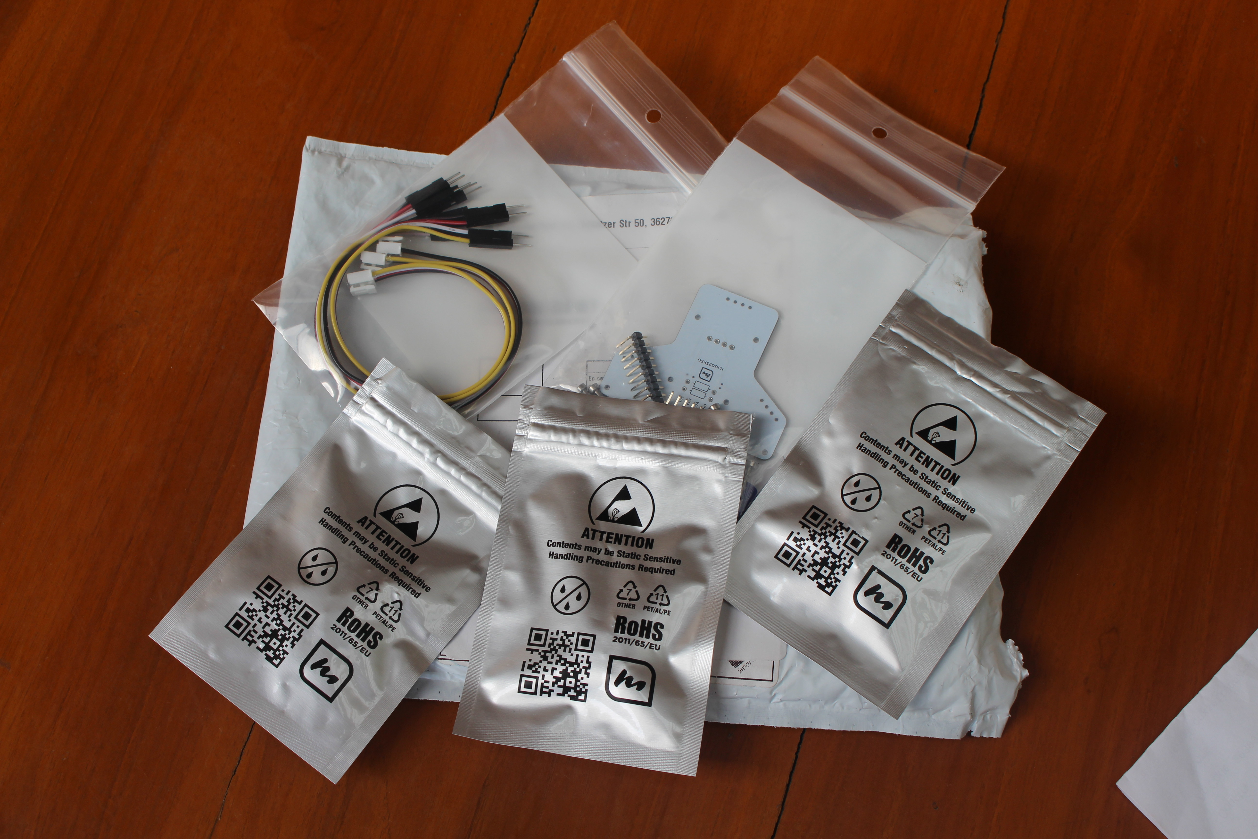
Opening them up revealed three TinyLIDAR boards, the corresponding Grove to jumper cables, and a bracket PCB for three TinyLIDAR boards together with headers and screws. So I looks like I received the “3 tinyLiDAR – IGG Special” plus the bracket board that was supposed to be a stretch goal unlocked at $25K (but they only got $23,717). Maybe that’s a good sign for backers, we’ll see.
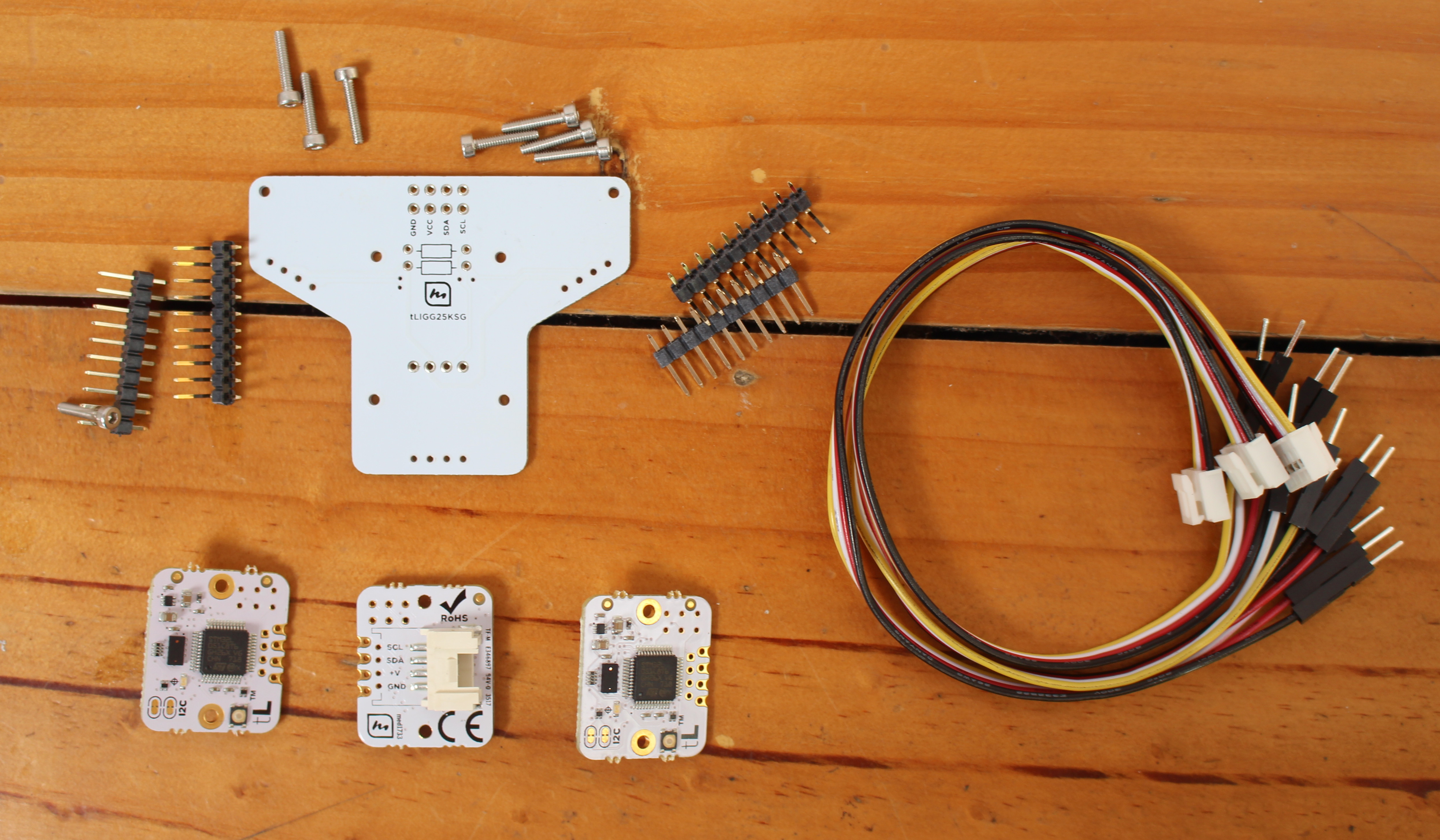
Due to time constraints, I won’t use the bracket, but only single boards. The brackets can be used with three tinyLIDAR boards using different I2C addresses, and you’ll see an example use with the Follow-me 2 Sketch where the 3 LIDAR boards are mounted on a tilt/pan platform that can track your hand.
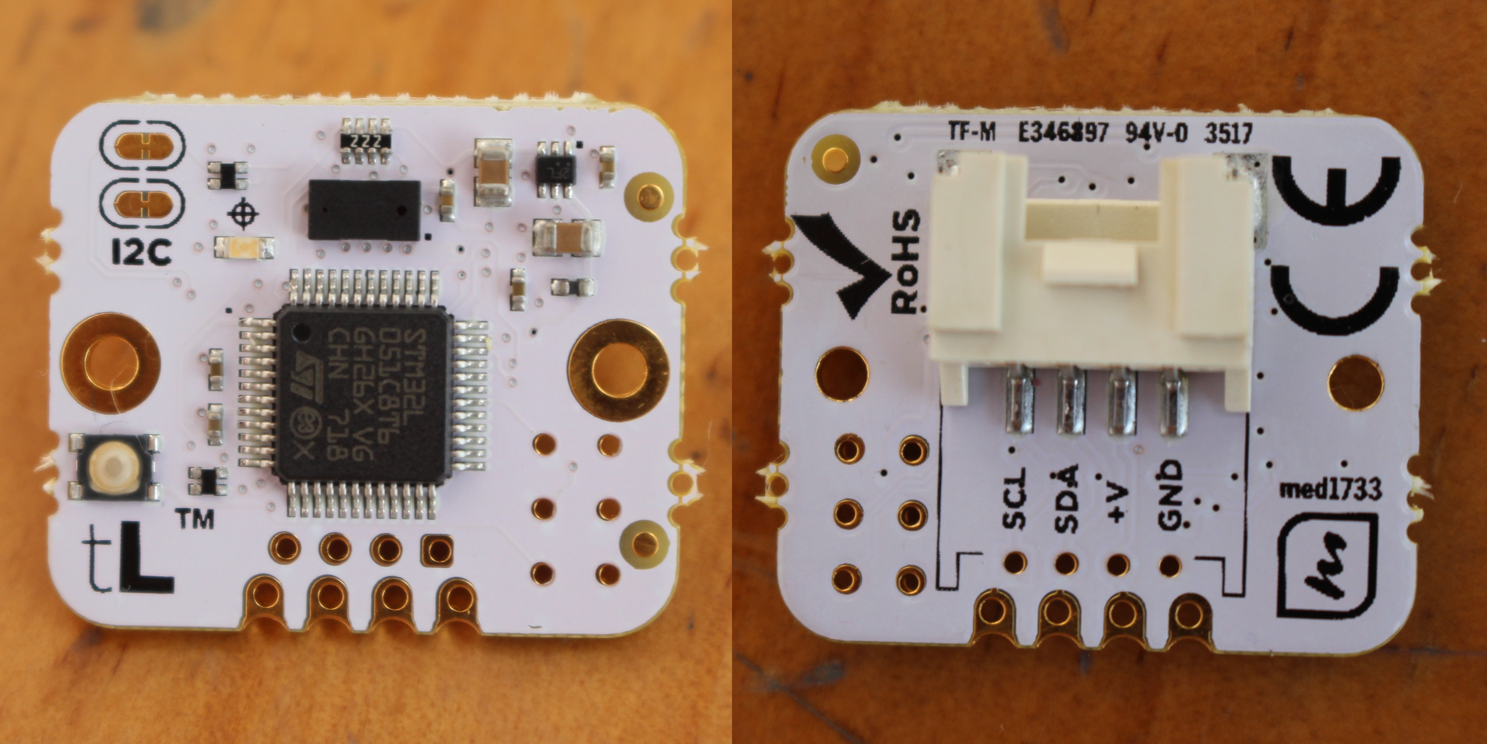
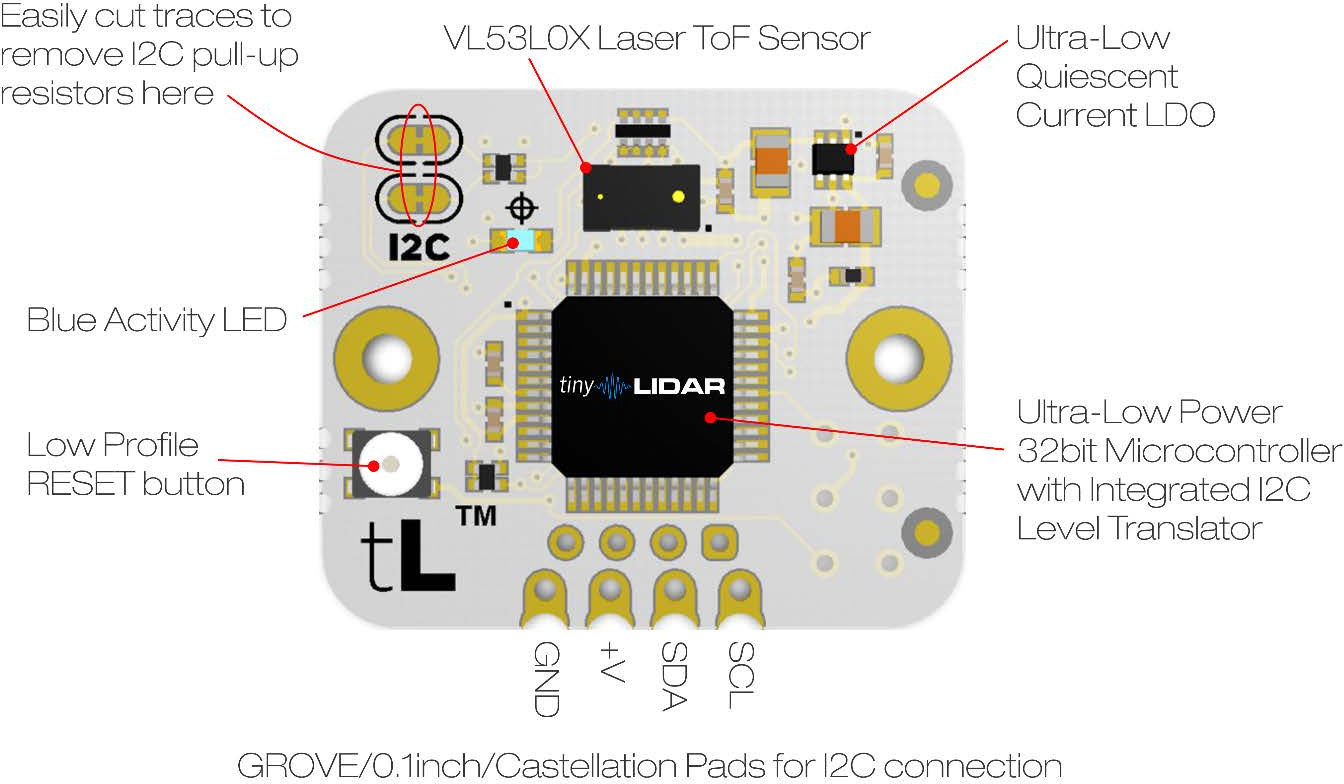
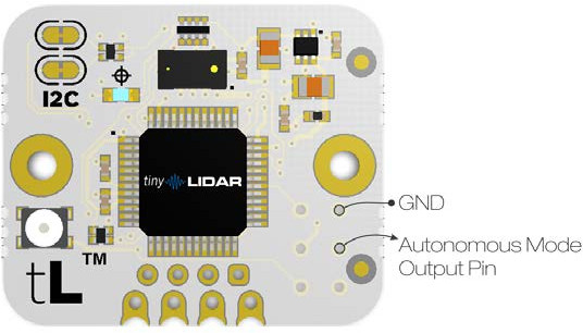
The bigger chip on the by is STM32L0 Cortex M0+ microcontroller with the much smaller STMicro VL53L0X laser ToF sensor placed right on top of it on the photo above. There are also a few I/O include the 4-pin I2C Grove connector and through holes, some pogopin for direct UART access, an LED, a reset button, and more, as described in the diagram below.

TinyLIDAR on Arduino
Now, it’s time to play with the board using sample and documentation on a dedicated page. Refer to this page for the latest versions, as below I’ll link to the versions I used for the review.
To easily evaluate and learn about the platform, the company has made what they call Arduino GUI Terminal sketch to let your control the device from an Arduino board using a serial terminal. https://microelectronicdesign.s3.amazonaws.com/tinyLiDAR_Terminal_GUI_1_1.ino
The company only tested Arduino Uno, but it turns out I don’t have one so I had to use an Arduino Leonardo clone instead, and after initial troubles, and help from my contact at the company (Dinesh), I could use tinyLiDAR_Terminal_GUI_1_24.ino with my boardsince it now supports Arduino Uno, Leonardo, and Mega .If you don’t use Arduino Uno (default), make sure you enable your board accordingly in the code by commenting out the relevant line:
|
1 2 3 4 5 |
// *** Please uncomment for your board type: *** //#define ArduinoLEONARDO #define ArduinoUNO //#define ArduinoMEGA |
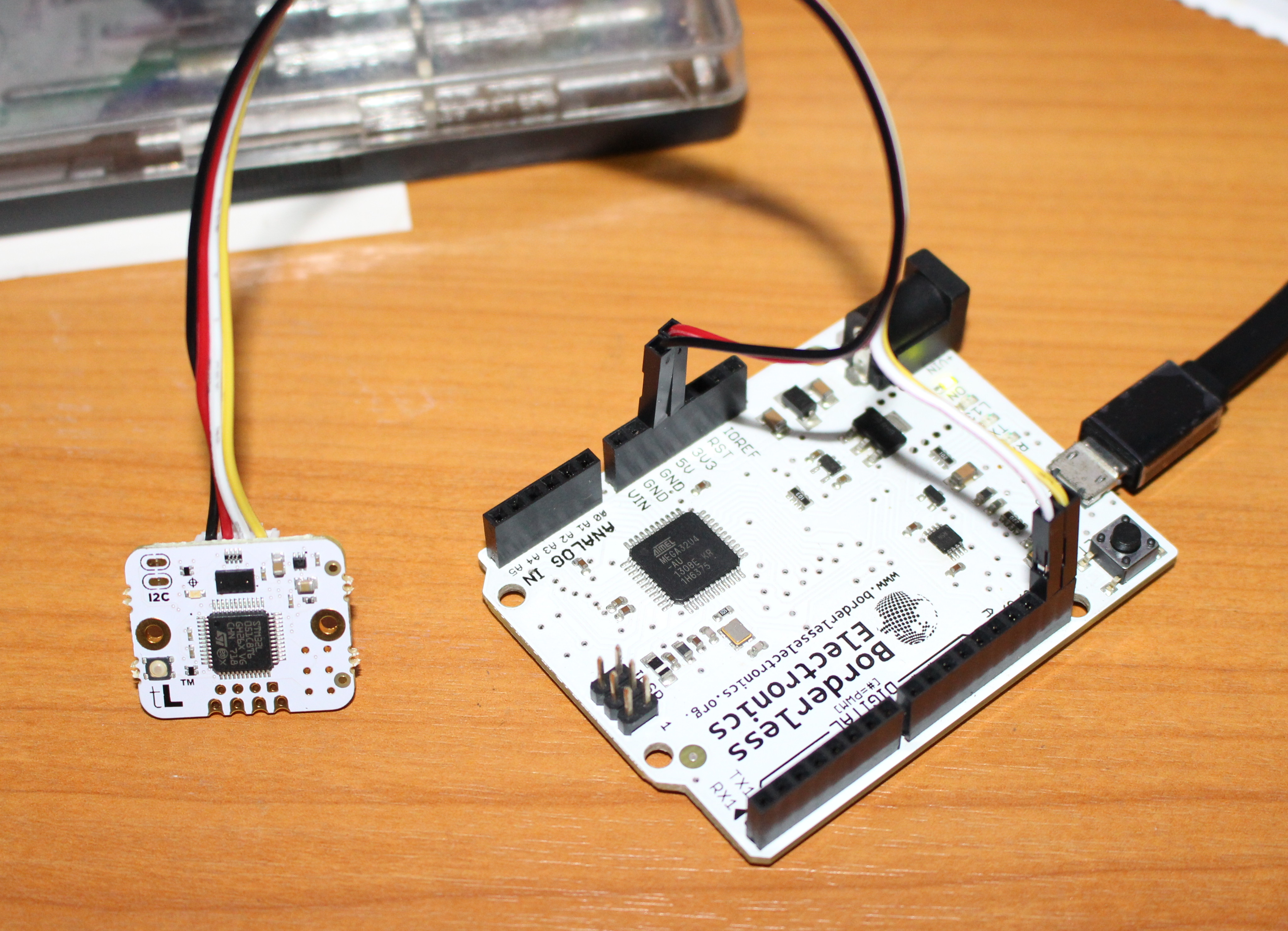
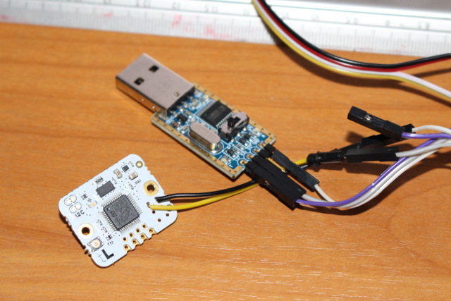
The hardware connections are very easy as you just need to connect the jumper cables to the I2C pins, 5V and GND on the board.
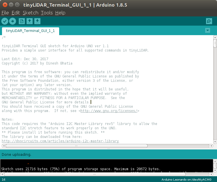
Once this was done I connect a micro USB cable to my computer, and tried to upload the ino sketch file, but it failed to compile. That’s because I forgot to install Arduino I2C Master Library, which can be downloaded here, and you just need to click on Sketch->Include Library->Add .ZIP library, and select the freshly downloaded I2C_Rev5.zip file to complete the installation. I could then build and upload the program to Arduino Leonardo.
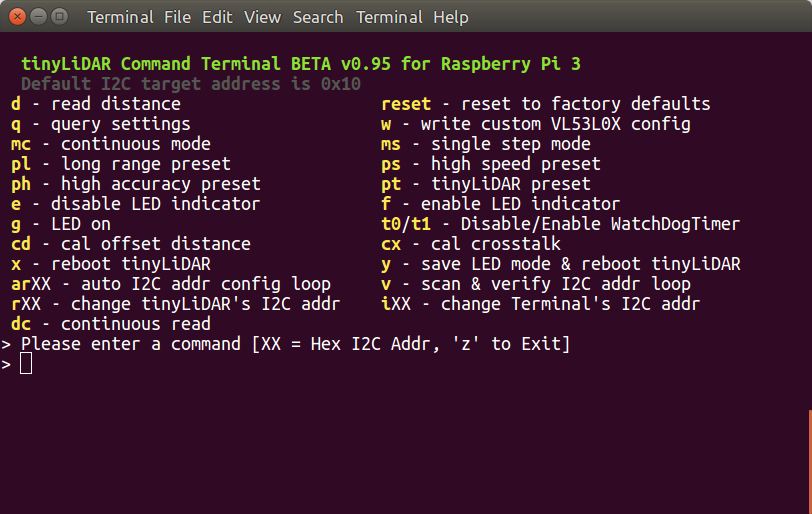
 Time to start a serial console using minicom, TeraTerm, Putty or others with 115200 8N1 and no flow control to access the Arduino GUI terminal:
|
1 2 3 4 5 6 7 8 9 10 11 12 13 14 |
Please enter a command [XX = hex I2C addr]: d - read distance :: reset - reset to factory defaults q - query settings :: w - write custom VL53L0X config mc - continuous mode :: ms - single step mode pl - long range preset :: ps - high speed preset ph - high accuracy preset :: pt - tinyLiDAR preset e - disable LED indicator :: f - enable LED indicator g - LED on :: t0/t1 - Disable/Enable WatchDog Timr cd - cal offset distance :: cx - cal crosstalk x - reboot tinyLiDAR :: y - save LED mode and reboot tinyLi arXX - auto I2C addr config loop :: v - scan & verify I2C addr loop rXX - change tinyLiDAR's I2C addr :: iXX - change Terminal's I2C addr ml - ss ultra low power mode :: a - start autonomous mode az - end autonomous mode |
You’ll get a list of command in the terminal, but you may want to read the reference manual to clearly understand each item.
I started with the query command, which worked just fine:
|
1 2 3 4 5 6 7 8 9 10 11 12 13 14 15 |
Command 'Q' to 0x10: Query tinyLiDAR Configuration Parameters >> Current Operation Mode is: SingleStep >> WatchDog Timer: ON >> LED Indicator: Measurement >> Current Preset Configuration is: tinyLiDAR >> Signal Rate Limit = 0.10 MCPS >> Sigma Estimate Limit = 60 mm >> Timing Budget = 18 ms >> Pre Range VCSEL Period = 18 >> Final Range VCSEL Period = 14 >> tinyLiDAR Firmware Version = 1.3.8 >> ST PAL API Version = 1.0.2 >> Offset Cal: Default >> Cal Offset = 45.0mm >> Xtalk = 0.000MCPS |
I could also use to read command, but to test accuracy I decided to use a ruler and a small box as shown below.
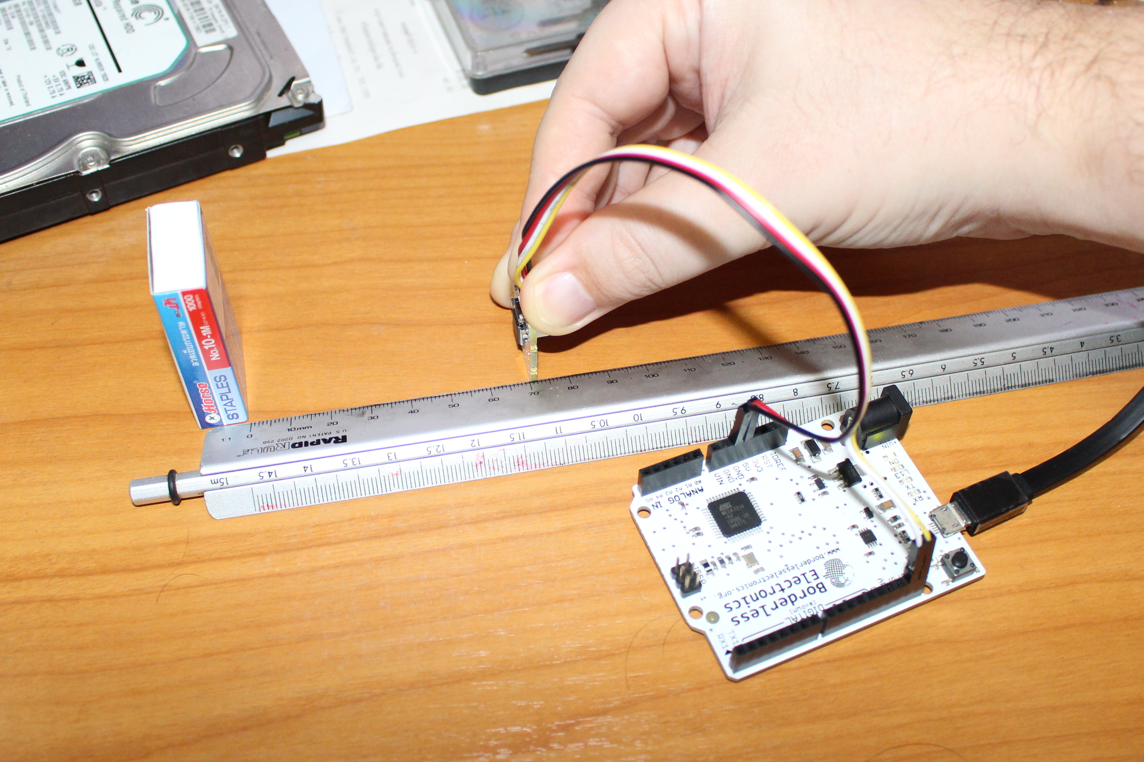
I tested 5cm and 10 cm:
- 5cm:
|
1 2 3 4 5 |
[default] Command 'D' to 0x10 Distance = 100mm [default] Command 'D' to 0x10 Distance = 100mm [default] Command 'D' to 0x10 Distance = 47mm [default] Command 'D' to 0x10 Distance = 47mm [default] Command 'D' to 0x10 Distance = 47mm |
- 10cm:
|
1 2 3 4 5 |
[default] Command 'D' to 0x10 Distance = 83mm [default] Command 'D' to 0x10 Distance = 83mm [default] Command 'D' to 0x10 Distance = 84mm [default] Command 'D' to 0x10 Distance = 79mm [default] Command 'D' to 0x10 Distance = 80mm |
Not that good…. But there’s a calibration command as explained in the reference manual:
CD Auto-Calibrate Distance Offset
Perform Offset Distance Calibration on tinyLiDAR.
Before using this calibration command, please set tinyLiDAR to Continuous, High Accuracy mode by issuing
the commands “MC” and “PH”. See example code in Appendix A for details.
ST recommends to use a distance of 100mm to a white target. Therefore, place a white target 100mm away
from tinyLiDAR before running this calibration.
Must specify calibration distance in mm.
The new offset correction distance will be placed in non-volatile memory and used for all subsequent
operations. This calibration takes about 10 seconds to run and the LED will flash slowly during the calibration.
You can reset to our factory defaults by executing the “RESET” command.
So let’s go ahead by placing the board at 10 cm from a white box (OK mine was not exactly white), run MC and PH commands (although it does not look necessary), before running running CD without parameter to do the actual calibration:
|
1 2 3 4 5 6 7 8 9 10 11 12 13 14 15 16 17 18 19 20 21 22 23 24 25 26 27 28 29 30 31 32 33 34 |
Command 'C D' to 0x10: Perform Offset Cal at a distance of = 100 mm : tinyLiDAR preset to High Accuracy configuration. : tinyLiDAR set to Continuous mode. Distance Before Cal: Distance = 96mm Distance = 96mm Distance = 95mm Distance = 96mm Distance = 95mm Distance = 94mm Distance = 94mm Distance = 95mm Distance = 94mm Distance = 95mm **** Calibrating Now - Please wait approx 10sec **** : reboot tinyLiDAR. Distance After Cal: Distance = 100mm Distance = 99mm Distance = 100mm Distance = 99mm Distance = 99mm Distance = 100mm Distance = 99mm Distance = 99mm Distance = 100mm Distance = 99mm **** Cal Complete **** |
Let’s go back to single step operation (ms) and tinyLIDAR preset (pt), and try the measurements again
- 5cm:
|
1 2 3 4 5 |
[default] Command 'D' to 0x10 Distance = 67mm [default] Command 'D' to 0x10 Distance = 67mm [default] Command 'D' to 0x10 Distance = 48mm [default] Command 'D' to 0x10 Distance = 49mm [default] Command 'D' to 0x10 Distance = 46mm |
- 10cm:
|
1 2 3 4 5 6 7 8 9 10 11 12 |
[default] Command 'D' to 0x10 Distance = 43mm [default] Command 'D' to 0x10 Distance = 43mm [default] Command 'D' to 0x10 Distance = 105mm [default] Command 'D' to 0x10 Distance = 92mm [default] Command 'D' to 0x10 Distance = 93mm [default] Command 'D' to 0x10 Distance = 97mm [default] Command 'D' to 0x10 Distance = 102mm [default] Command 'D' to 0x10 Distance = 102mm [default] Command 'D' to 0x10 Distance = 104mm [default] Command 'D' to 0x10 Distance = 99mm [default] Command 'D' to 0x10 Distance = 96mm [default] Command 'D' to 0x10 Distance = 102mm |
It’s getting better, although the first two steps always seen to be stuck to some previous measurements. I’ve been told it may be due to some buffer in the serial terminal.
Trying some longer distances:
- 20cm:
|
1 2 3 4 5 6 7 8 9 |
[default] Command 'D' to 0x10 Distance = 104mm [default] Command 'D' to 0x10 Distance = 96mm [default] Command 'D' to 0x10 Distance = 201mm [default] Command 'D' to 0x10 Distance = 206mm [default] Command 'D' to 0x10 Distance = 190mm [default] Command 'D' to 0x10 Distance = 190mm [default] Command 'D' to 0x10 Distance = 192mm [default] Command 'D' to 0x10 Distance = 196mm [default] Command 'D' to 0x10 Distance = 198mm |
- 30cm:
|
1 2 3 4 5 6 7 8 9 |
[default] Command 'D' to 0x10 Distance = 188mm [default] Command 'D' to 0x10 Distance = 189mm [default] Command 'D' to 0x10 Distance = 299mm [default] Command 'D' to 0x10 Distance = 308mm [default] Command 'D' to 0x10 Distance = 294mm [default] Command 'D' to 0x10 Distance = 303mm [default] Command 'D' to 0x10 Distance = 300mm [default] Command 'D' to 0x10 Distance = 302mm [default] Command 'D' to 0x10 Distance = 297mm |
It’s basically doing the job. If you need more accuracy, longer range, or faster measurements, you can change the mode:
- PL: long range mode (up to 2m, 33ms)
- PS: high speed mode (up to 1.2m, 20ms)
- PH: high accuracy mode (up to 1.2m, 200ms)
- PT: tinyLiDAR mode (up to 2m, 18ms)
One interesting feature, especially if you run on batteries, is the autonomous mode where the board is configured to automatically check the distance range every X second, and trigger a pulse when within range, without having to send I2C commands from the host, except the initial one. In the Arduino GUI terminal, you can for example run:
|
1 2 3 4 5 6 7 8 9 10 11 12 13 14 15 |
A 10 200 30 10 1 Command 'A': Autonomous Mode. The values you entered were - Low side limit = 10 mm High side limit = 200 mm Repetition interval = 30 for 3000 ms Pulse Width = 10 for 1000 ms LED indicator = ON : reboot tinyLiDAR. : tinyLiDAR set to SingleStep mode. : Now writing parameters to tinyLiDAR. |
From there, you won’t show anything in the Arduino terminal, so you can either monitor the autonomous pin – as shown in the diagram below – with the host board or a multimeter…
… or instead you may consider soldering GND and serial TX pins on tinyLIDAR board, and access the read-only console use a USB to TTL debug board as shown below.
The terminal needs to be set to 115200 7N1 without flow control, and you’ll should an output similar to the one below when you run the A command above:
|
1 2 3 4 5 6 7 8 9 10 11 12 13 14 15 16 17 18 19 20 21 22 23 24 25 26 27 28 29 30 31 32 33 34 35 36 37 38 39 40 41 42 43 44 45 46 47 48 49 50 51 52 53 54 55 56 57 58 59 60 |
> tinyLiDAR FW: 1.3.8 > ST PAL API: 1.0.2 > WatchDog: on > LED: measurement > I2C Address: 0x10 > Presets: tinyLiDAR SignalLimit 0.10 Mcps SigmaLimit 60 mm TimingBudget 18 ms PreRangeVcselPeriod 18 FinalRangeVcselPeriod 14 > Offset Cal: Default = 50 mm > Xtalk Cal: Default > Ready 0 | 1384960 : 27 mm, 27 mm. =======>>>>>>> the LOW limit is this from arduino --->> 10 =======>>>>>>> the HIGH limit is this from arduino --->> 200 =======>>>>>>> the Rep Intv limit is this from arduino --->> 30 =======>>>>>>> the PW is this from arduino --->> 10 > WDT Enabled > Autonomous mode set > Reboot > tinyLiDAR FW: 1.3.8 > ST PAL API: 1.0.2 > WatchDog: on > LED: measurement > I2C Address: 0x10 > Presets: tinyLiDAR SignalLimit 0.10 Mcps SigmaLimit 60 mm TimingBudget 18 ms PreRangeVcselPeriod 18 FinalRangeVcselPeriod 14 > Offset Cal: Default = 50 mm > Xtalk Cal: Default > Ready 0 | 1385984 : 20 mm, 20 mm. > Autonomous mode setting detected > Now going to autonomous mode. 0 | 1344512 : 21 mm, 24 mm. 0 | 1355264 : 21 mm, 22 mm. ... 0 | 166400 : 67 mm, 124 mm. 0 | 32768 : 681 mm, 1594 mm. 0 | 29696 : 1038 mm, 1570 mm. 0 | 26624 : 1216 mm, 1482 mm. 0 | 33280 : 1357 mm, 1568 mm. 0 | 33792 : 1408 mm, 1485 mm. 0 | 73728 : 947 mm, 264 mm. |
Just to be extra clear, at this stage I have two serial terminal in my computer:
- /dev/ttyACM0 connected to Arduino where I can input commands
- /dev/ttyUSB0 connected directly to tinyLIDAR where I can see debug output (read-only)
If you want to integrate it into your own program, you’ll have to send commands as shown by the Arduino sketch to read distance:
|
1 2 3 4 5 6 7 8 9 10 11 12 13 14 15 16 17 18 19 20 21 22 23 |
#define SCL_PORT PORTC #define SDA_PORT PORTC #define SCL_PIN 5 //std SCL pin #define SDA_PIN 4 //std SDA pin #include <I2C.h> void setup() { Serial.begin(115200); //setup the serial port I2c.begin(); } //setup void loop() { uint16_t i; while(1) { I2c.write(0x10,'D'); //take single measurement I2c.read(0x10,2); // request 2 bytes from tinyLiDAR i = I2c.receive(); // receive MSB byte i = i<<8 | I2c.receive(); // receive LSB byte and put them together Serial.println(i); // print distance in mm delay(100); // delay as required (13ms or higher in default single step mode) } //while } //loop |
The code above is for Arduino Uno, so if you use Arduino MEGA or Leonardo you’ll need to change the PORT to PORTD, and SCL and SDA to pin 0 and 1 respectively.
TinyLIDAR on Raspberry Pi 2/3
Arduino is cool, but if your project is better suited to Raspberry Pi board, you can also connect tinyLIDAR to the I2C port of Raspberry Pi 2/3, or any other Raspberry Pi boards. The instructions are explained in details on Instructables, also explaining some of the shortcomings of I2C on Raspberry Pi board (lack of clock stretching support, pull up resistors installed). The steps are very details, even suitable to people having never used a Raspberry Pi, so here I’ll go faster focusing on settings specific to tinyLIDAR use.
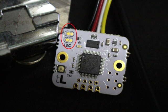
First you need to scratch the I2C PCB trace on tinyLIDAR with a cutter to disconnect the pull-up resistors since it’s already done on the Raspberry Pi board. Now we can connect tinyLIDAR to the I2C pins, as well as 3.3V and GND.

I used the same Raspbian Stretch Lite image with SSH enabled (/boot/ssh file present) as I did for ANAVI Light pHAT. Now we need to install pigpio in Raspberry Pi as follows:
|
1 2 |
sudo apt update sudo apt install pigpio python-pigpio python3-pigpio i2c-tools |
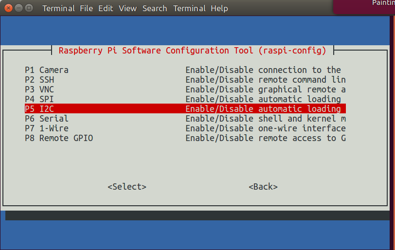
You’ll also need o run raspi-config to enable I2C.
The next step is optional, but I still recommend it as at the beginning I had trouble finding tinyLIDAR. That’s the step to detect tinyLIDAR I2C address:
|
1 2 3 4 5 6 7 8 9 10 |
sudo i2cdetect -y 1 0 1 2 3 4 5 6 7 8 9 a b c d e f 00: -- -- -- -- -- -- -- -- -- -- -- -- -- 10: 10 -- -- -- -- -- -- -- -- -- -- -- -- -- -- -- 20: -- -- -- -- -- -- -- -- -- -- -- -- -- -- -- -- 30: -- -- -- -- -- -- -- -- -- -- -- -- -- -- -- -- 40: -- -- -- -- -- -- -- -- -- -- -- -- -- -- -- -- 50: -- -- -- -- -- -- -- -- -- -- -- -- -- -- -- -- 60: -- -- -- -- -- -- -- -- -- -- -- -- -- -- -- -- 70: -- -- -- -- -- -- -- -- |
We can see 0x10 I2C address is detected, and that’s our tinyLIDAR board. If you don’t have any addresses detected, re-check your connections.
Now that we have confident the hardware is OK, we can install “RPI TinyLIDAR Terminal GUI”:
|
1 2 3 4 5 |
cd ~ mkdir tinyLiDAR cd tinyLiDAR/ wget https://microedco.s3.amazonaws.com/tinyLiDAR/Raspberry%20Pi/rpi_tinyLiDAR_TerminalGui.zip unzip rpi_tinyLiDAR_TerminalGui.zip |
and launch it with:
|
1 |
python tlgui.py |
From there, it’s the same as in the Arduino terminal GUI, for example read and query commands:
|
1 2 3 4 5 6 7 8 9 10 11 12 13 14 15 16 17 18 19 20 |
> d # Distance = 38 mm > q Current Operation Mode is: SingleStep WatchDog Timer: ON LED Indicator: Measurement Current Preset Configuration is: tinyLiDAR Signal Rate Limit = 0.10 MCPS Sigma Estimate Limit = 60 mm Timing Budget = 18 ms Pre Range VCSEL Period = 18 Final Range VCSEL Period = 14 tinyLiDAR Firmware Version = 1.3.8 ST PAL API Version = 1.0.2 Offset Cal: Factory Cal Offset = 44.0 mm Xtalk = 0.000 MCPS > Press ENTER to Continue |
Again the RPi terminal GUI is just for evaluation, but you can study the Python in order to integrate support for tinyLIDAR into your own Python application.
That’s all for this getting started guide.
The crowdfunding campaign is now over, but you can buy TinyLIDAR board directly on MicroElectronic Design website for $24.95. You’ll also find the bracket board for $4.95 and a pack of 100 mounting screws on that page. Further details may also be found on the product page.

Jean-Luc started CNX Software in 2010 as a part-time endeavor, before quitting his job as a software engineering manager, and starting to write daily news, and reviews full time later in 2011.
Support CNX Software! Donate via cryptocurrencies, become a Patron on Patreon, or purchase goods on Amazon or Aliexpress


Nice sensor, shame the FoV is a bit wide
@malem
Unfortunately FoV won’t be changing – I asked ST about this, and the reason for the wide FoV is to keep it eye safe – a more concentrated beam would require appropriate warnings and eye protection. Also, wider beam is probably better for its primary use as a prox detector on smart phones (which brings volume way up and prices down for the rest of us).
if you use a pi or any other descent contoller you can better buy a standalone VL53L0X I2C board on ebay for like 4€
Nice work 🙂
Just like Jeroen, I am questionning the concept of this board that basically add a STM to interface the VL53L0X , that we can otherwise easily connect directly to an Arduino or RPI usingI2C and existing libraries at 1/6 the price …
I’m with Jeroen and Patrick, I’ve used this sensor on a couple projects and I don’t understand adding an I2C interface on top of an I2C interface that the part has; and worse it seems there Firmware is buffering stuff badly; for RPI, ST already provides a complete stack to talk to the sensor; (It is a pain to hack up to use on a microcontroller; but it has been done)
i get for 37 cents
https://www.aliexpress.com/item/Smart-Electronics-New-for-Arduino-Diy-Smart-Car-Robot-Reflective-Photoelectric-3pin-IR-Infrared-Obstacle-Avoidance/32461659104.html
@TonyT
Yeah I thought as much. Don’t get me wrong it’s great at what it does, I just can’t help but imagine the cool things you could.
I’m wondering if you could restrict the view of the photo diode using some kind of focus. Accuracy and speed would probably suffer but it might just be good enough.
@salom
That $0.37 IR sensor is not at all the same thing as ST’s Time of Flight sensor