
Earlier this month, I installed Match MatchBox LoRa outdoor gateway close to the roof, and showed how easy it was easies to setup with MatchX Cloud. Basically, you just register to the cloud, enter the serial number, and the gateway is automatically based on your location. I’m in South East Asia, so the gateway was configured with AS923.
I’ve now had time to play with the gateway using Rak Wireless RAK811 LoRa tracker board, and eventually managed to get the tracker location to show up on a map. It was my first experience with LoRaWAN, and I had to learn a lot, and overcome many issues from outdated software development tools, different data formats, and some interoperability issues between all components involved. I’ll document all that in this review, and hopefully it will help others.
RAK811 LoRa GPS Tracker Unboxing
Before going into LoRa configuration, I’ll show what I got with RAK811 node.
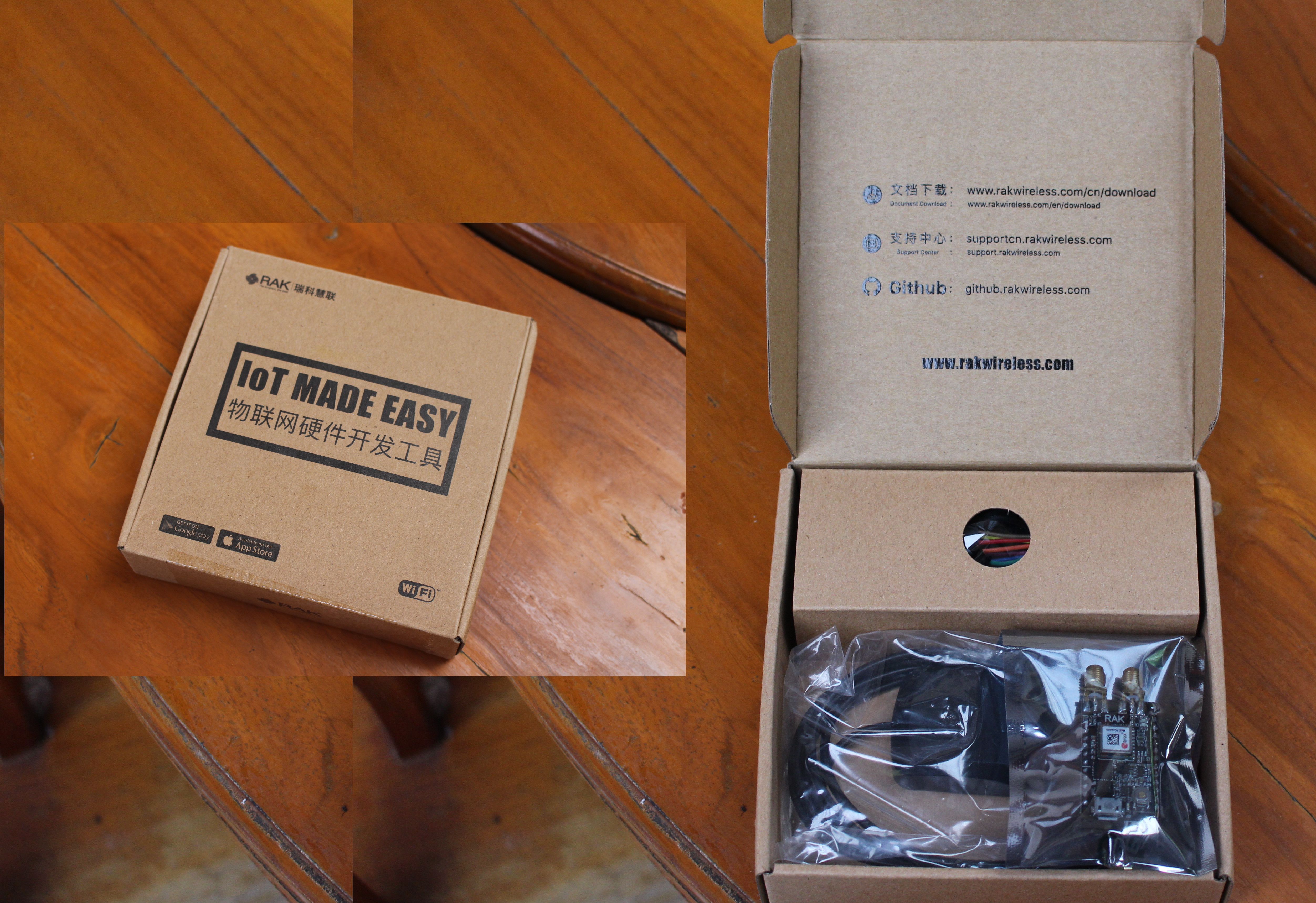
It comes with an “IoT Made Easy” package with links to documentation and software.
We’ll get the board, a GPS antenna with a long cable, a LoRa antenna, a micro USB cable, a cable for the battery, and a plastic bag with some jumpers and Dupont cables.
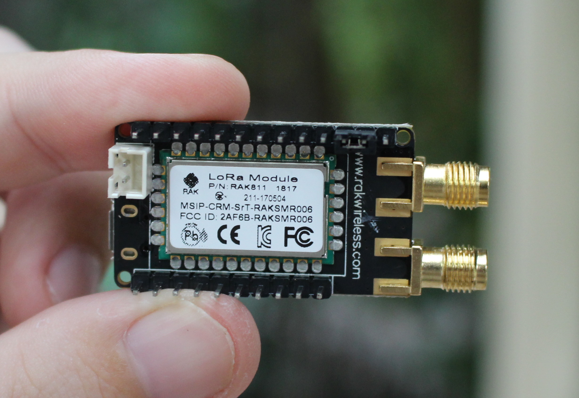
One side of the board comes with RAK811 LoRa module, the 2-pin header for the battery, and male headers for I/Os. The jumper on th top right is used to select boot mode, but more on that later.
The other side includes u-blox MAX-7Q GPS module, a micro USB port, and the reset button. We also have two SMA connectors for the antennas.
RAK811 Tracker Hardware Setup
Th kit does not include any battery due to airline / customs regulations, so I bought a 18650 battery and battery holder locally…
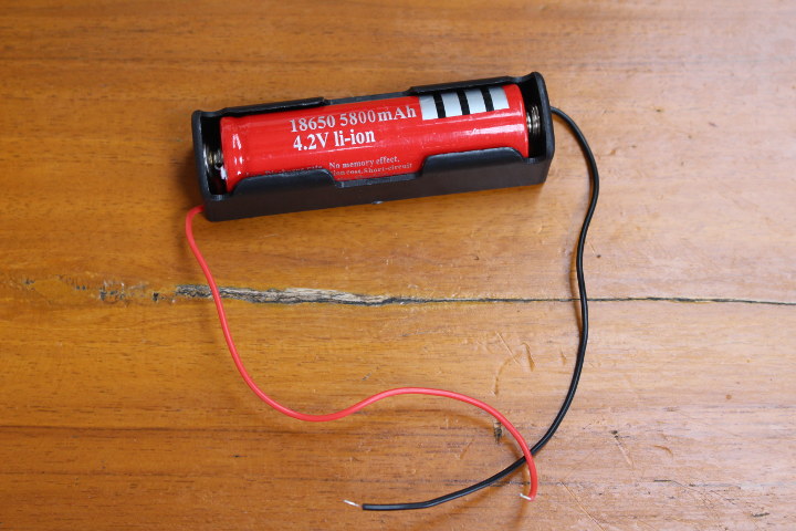
.. and soldered it to the provided wires and connector, before inserting it into the board.
You’ll also need to connect the GPS and LoRa antennas. I had to spend some time to find out, as there’s no marking on the board, and no mention whatsoever in the documentation. I eventually found which SMA connector was for which antenna in the Aliexpress page…
Time to connect the micro USB to USB cable between the port and my computer to find out more, and configure the board.
RAK811 LoRa Tracker Info, Development Tools, and Firmware
I’m normally using Ubuntu 16.04, so here’s the kernel output when I insert device in computer:
|
1 2 3 4 5 6 7 8 9 10 11 12 13 |
7521.899484] usb 1-2.4.3: new full-speed USB device number 5 using ehci-pci [ 7522.029424] usb 1-2.4.3: New USB device found, idVendor=10c4, idProduct=ea60 [ 7522.029427] usb 1-2.4.3: New USB device strings: Mfr=1, Product=2, SerialNumber=3 [ 7522.029429] usb 1-2.4.3: Product: CP2102 USB to UART Bridge Controller [ 7522.029431] usb 1-2.4.3: Manufacturer: Silicon Labs [ 7522.029433] usb 1-2.4.3: SerialNumber: 0001 [ 7523.088561] usbcore: registered new interface driver usbserial [ 7523.088613] usbcore: registered new interface driver usbserial_generic [ 7523.088659] usbserial: USB Serial support registered for generic [ 7523.091652] usbcore: registered new interface driver cp210x [ 7523.091687] usbserial: USB Serial support registered for cp210x [ 7523.091747] cp210x 1-2.4.3:1.0: cp210x converter detected [ 7523.093893] usb 1-2.4.3: cp210x converter now attached to ttyUSB0 |
It’s a typical serial device. We can connect to /dev/ttyUSB0 using minicom or other serial terminal program with 115200 bps 8N1 configuration. Then press the reset button or short the reset and GND pins with a jumper, remove it, to reboot the board:
|
1 2 3 4 5 6 7 8 9 10 11 12 13 14 15 16 17 18 19 20 21 22 23 |
RAK811 BreakBoard soft version: 1.0.2 Selected LoraWAN 1.0.2 Region: EU868 ABP: Dev_EUI: 60 C5 A8 FF FE 00 00 10 DevAddr: 004B041B NwkSKey: 2B 7E 15 16 28 AE D2 A6 AB F7 15 88 09 CF 4F 3C AppSKey: 2B 7E 15 16 28 AE D2 A6 AB F7 15 88 09 CF 4F 3C [Debug]: latitude: 0.000000, longitude: 0.000000 , altitudeGps: -1 Move Detected INT1 src:0x42 Move Detected INT1 src:0x41 Move Detected INT1 src:0x42 Move Detected INT1 src:0x50 Move Detected INT1 src:0x50 [Debug]: tempr: 34 Bat: 5500mv [Debug]: ACC X:FF00 Y:FF00 Z:0000 Move Detected INT1 src:0x60 [Debug]: latitude: 0.000000, longitude: 0.000000 , altitudeGps: -1 Move Detected INT1 src:0x44 Move Detected INT1 src:0x60 Move Detected INT1 src:0x50 Move Detected INT1 src:0x50 |
EU868 was not exactly what I was expecting, since I was told the board would be configured with AS923. But it turns out it’s not an issue, and the user is the one suppose to configure the tracker accordingly.
The pre-installed firmware was a little old (1.0.2), while the latest release on Github was v1.1.3 which adds support for AT commands. The documentation explains how to build the firmware with CooCox CoIDE or Arm Keil both of which are only available for Windows. Some people managed to built it with a Makefile in Linux, and submitted a pull request, but it was not approved, and now conflicts with other code. Let’s keep things as simple as possible, and fire a VirtualBox sessions with Windows 7.
The first step is to download CooCox CoIDE, an Arm GNU Embedded Toolchain, and get the code from github to open the project, modify it for AS923 as per the documentation, and build it in CoIDE. It seems easy enough, but the first roadblock was to download CooCox CoIDE itself, I only found an older version, and the build would then failed. The documentation – at the time of writing – is also outdated since it was before AT commands method was introduced. Anyway, eventually Rak provided a link to a newer version of CooCox CoIDE, and I managed to build the firmware. We only found this solution near the end of the review, so instead I flashed the binary release: rak811_tracker_classA.bin.
You have three options to flash the firmware from Keil or CoIDE via STLink J-Link debugger, or via USB using STMicro Flash Loader Demonstrator. The latter seems easier since it does not require extra hardware. I tried to download it from the link on Rak Wireless documentation page, but it was slow and unreliable, so a better option is to get it directly from STMicro website.
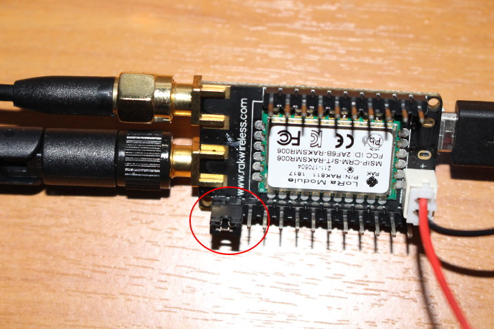 First we need to move the jumper to short BOOT0 and VCC to enter serial boot mode as shown above, and below with RAK811 tracker pinout diagram.
![]() Press the reset button to restart the board, and we’re now ready to use Flash Loader Demonstrator.
Press the reset button to restart the board, and we’re now ready to use Flash Loader Demonstrator.
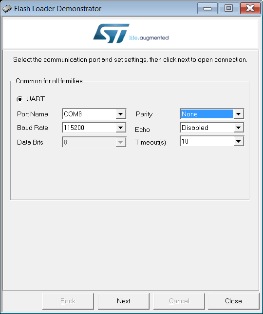
First select the Port Name, in my case COM9, and click Next, you should be told the board is detected. If not, you may have forgotten to place the jumper correctly and/or reboot the board.
Click Next again, and select STM32L1_Cat2-128K from the list.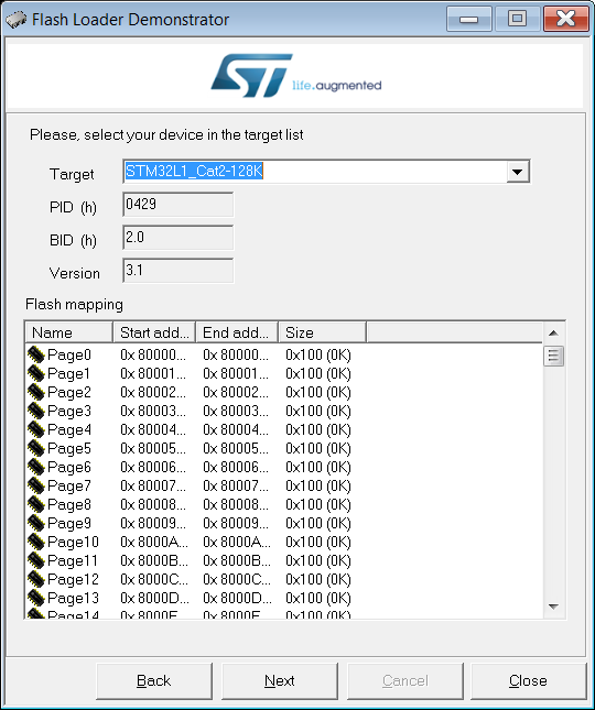
Press Next button again to select the firmware file we’ve just downloaded “rak811_tracker_classA.bin”.![]()
Leave all other settings unchanged, and click Next button to start downloading data to the board, and flash the firmware.
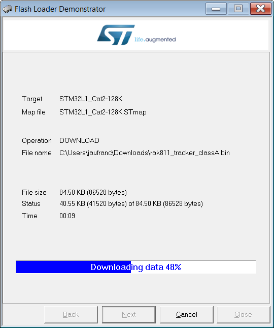
It should only take a few seconds. Once everything is done, you’ll be greeted with a “Download operation finished successfully” message.![]()
Now move the jumper back in position with BOOT0 and GND shorted, connect the serial terminal, and press the reset button.
Configuring RAK811 Tracker with OTAA or ABP join method.
That’s the output from the terminal:
|
1 |
RAK811 BreakBoard soft version: 1.1.3 |
and nothing else. That’s because we are supposed to input the AT command for configuration as briefly explained in Github:
AT command list:
at+region=EU868/US915/AS923/AU915/IN865/KR920 // Set device regionat+dev_eui=xxxxxxxxxxxxxxxx // Set device dev_eui
at+app_eui=xxxxxxxxxxxxxxxx // Set device app_eui
at+app_key=xxxxxxxxxxxxxxxxxxxxxxxxxxxxxxxx // Set device app_keyat+dev_addr=xxxxxxxx // Set device dev_addr
at+nwks_key=xxxxxxxxxxxxxxxxxxxxxxxxxxxxxxxx // Set device nwks_key
at+apps_key=xxxxxxxxxxxxxxxxxxxxxxxxxxxxxxxx // Set device apps_keyat+join_mode=otaa/abp // Set the device to join otaa or abp
Before we go further we should try to understand about the two methods:
- Over-the-Air Activation (OTAA) is the preferred and most secure way to connect. Devices perform a join-procedure with the network, during which a dynamic DevAddr is assigned and security keys are negotiated with the device.
- Activation by Personalization (ABP) hardcodes the DevAddr parameter as well as the security keys in the device. This means activating a device by personalization (ABP). This strategy might seem simpler, because you skip the join procedure, but it has some downsides related to security.
OTAA requires three parameters some identifiers, other security keys:
- DevEUI – 64 bit end-device identifier, EUI-64 (unique)
- AppEUI – 64 bit application identifier, EUI-64 (unique)
- AppKey – 128-bit application key
OTAA joint method then automatically generates DevAddr, NwksKey, and AppsKey (notice the extra “s”), but those parameters need to be specified in ABP join mode:
- DevAddr – 32 bit device address (non-unique)
- NwkSKey – 128-bit network session key used for interaction between the Node and the Network
- AppSKey– 128-bit application session key used for encryption and decryption of the payload
OTAA appears to be the best method, so let’s go that way.
|
1 2 3 4 5 |
at+dev_eui=60c5a8fffe000010 at+app_eui=70b3d57ed0007dfa at+app_key=b429c9c903d8442c5bf684fb5ef00219 at+region=AS923 at+join_mode=otaa |
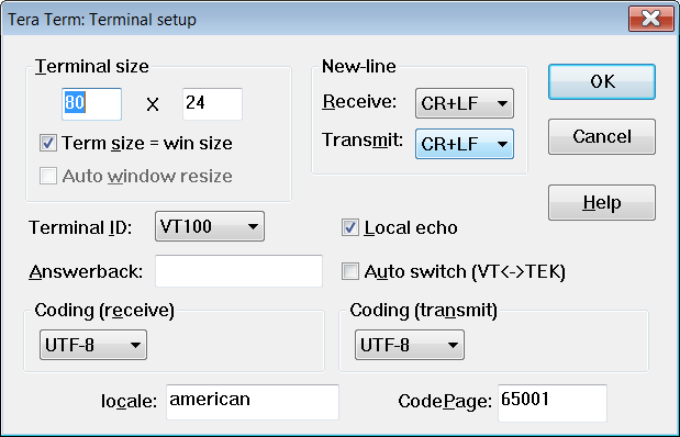
The first three line defines the parameters discussed above, and the last two set the region, and join mode. It looks like you can make any number up as long as they are 64-bit or 128-bit in length as specified previsouly. I initially had troubles pasting the AT commands in minicom, and I’ve been told they must be pasted one line at a time with “/r/n” (new line) at the end. I tried various terminals, and Tera Term worked for me after changing the settings to send (and receive) CR+LF line new-line in Setup->Terminal
Whichever terminal you use, the trick is to add a new line after each command.
The at+join_mode command must be the last one, as once I send that command, others are ignored…
|
1 2 3 4 5 6 7 8 9 10 11 |
at+join_mode=otaa OK OTAA: Dev_EUI: 60 C5 A8 FF FE 00 00 10 AppEui: 70 B3 D5 7E D0 00 7D FA AppKey: B4 29 C9 C9 03 D8 44 2C 5B F6 84 FB 5E F0 02 19 |
Adding a LoRa Application & Device to MatchX Cloud
So we’ve now configured RAK811 node with the necessary parameters, so we need to go to MatchX Cloud to create an application and add a new device with the same parameters.
 I created gps-tracking application in order to track a bicycle location, at least that was the plan. Once you have your new application ready, you can click on “Create Node” and add a new device as shown below with DevEUI, AppEUI – and AppKey parameters.
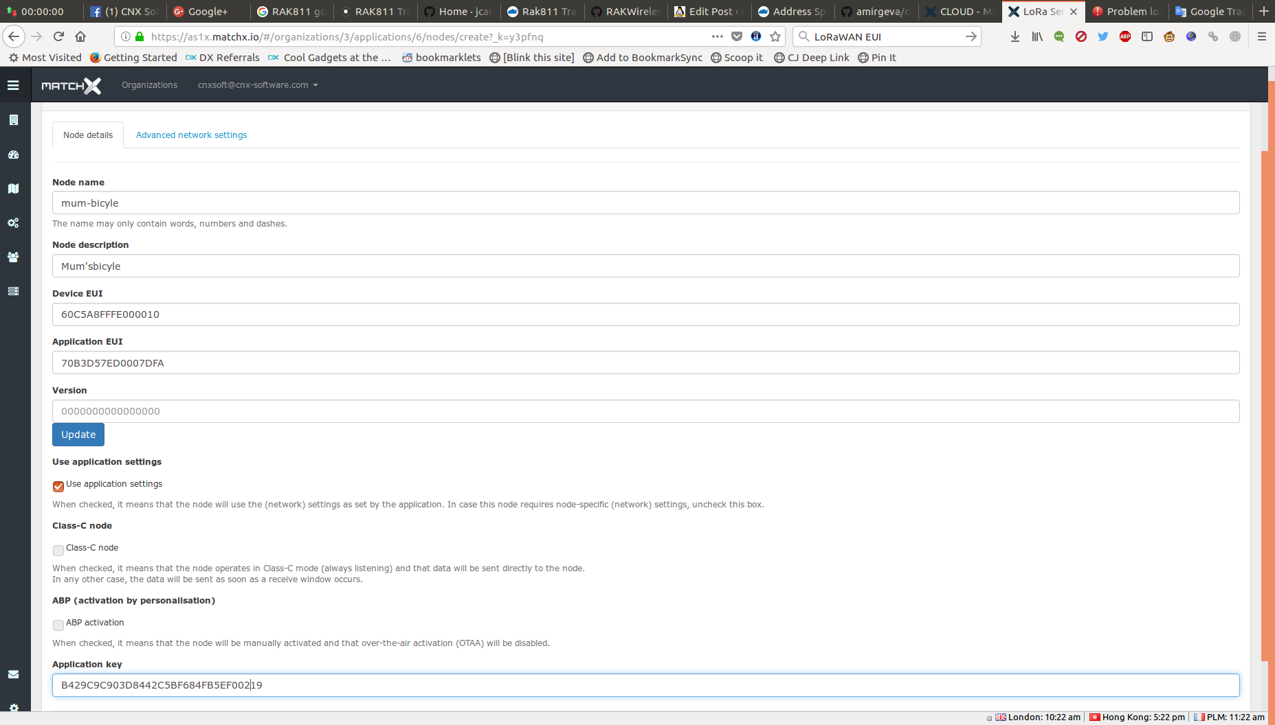
Leave ABP unchecked since we want to use OTAA join mode, and click on the Submit button.
First LoRaWAN Connection
Now we can press the reset button on RAK811 tracker board, and see what happens in the serial console:
|
1 2 3 4 5 6 7 8 9 10 11 12 13 14 15 16 17 18 19 20 21 22 23 24 25 26 27 28 29 30 31 32 33 34 35 36 37 |
RAK811 BreakBoard soft version: 1.1.3 Selected LoraWAN 1.0.2 Region: AS923 OTAA: Dev_EUI: 60 C5 A8 FF FE 00 00 10 AppEui: 70 B3 D5 7E D0 00 7D FA AppKey: B4 29 C9 C9 03 D8 44 2C 5B F6 84 FB 5E F0 02 19 OTAA Join Start... Move Detected INT1 src:0x42 Move Detected INT1 src:0x50 Move Detected INT1 src:0x50 Move Detected INT1 src:0x50 OTAA Join Success [Debug]: latitude: 0.000000, longitude: 0.000000 , altitudeGps: -1 Move Detected INT1 src:0x50 [Debug]: tempr: 33 Bat: 5496mv [Debug]: ACC X:0000 Y:0000 Z:FF00 [Debug]: latitude: 0.000000, longitude: 0.000000 , altitudeGps: -1 [Debug]: tempr: 33 Bat: 5500mv Move Detected INT1 src:0x50 Move Detected INT1 src:0x44 |
Good, the device could join the network, and we have various information like temperature, battery level, and accelerometer data. We’d need to wait a little longer to get GPS coordinates once the fix is in.
Good, let’s see what we’ve got in MatchX Cloud.
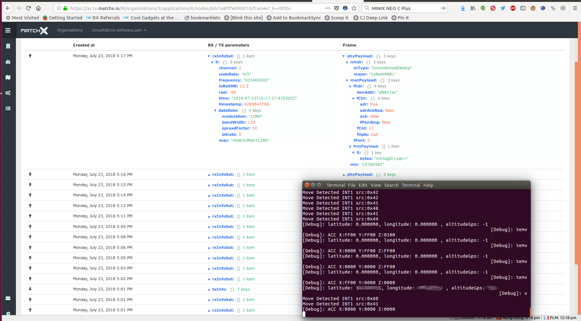
Awesome! We have some packets received every second (that’s what the firmware in RAK811 is supposed to do by default), and surely I’d be able to see RAK811 node location in the map in MatchX Cloud once the board gets GPS Fix. But not, nothing…
After studying a bit more including the documentation to setup RAK811 tracker node with The Things Network, I found out the data was sent in Cayenne Low Power Payload (LPP) format, and the gateway would not decode this type of data, so I asked MatchX whether it was possible to change that, and got the following answer:
When it comes to the data format – we are using different data encoding in a Type-Length-Value (TLV) format.
At this moment our cloud mapper is able to work only with this format. We are working on the major update of our Cloud and allowing more data parsers is on our check list, but this will still take us some time.
Connecting MatchX MatchBox LoRa Gateway to The Things Network
The good news is that Cayenne LPP will likely soon be supported, but I’d rather finished my review in a few days, rather than a few months. So since Rak wireless provided instructions to setup RAK811 with The Things Network (TTN), I decided to reconfigure the gateway to connect to TTN instead of MatchX Cloud.
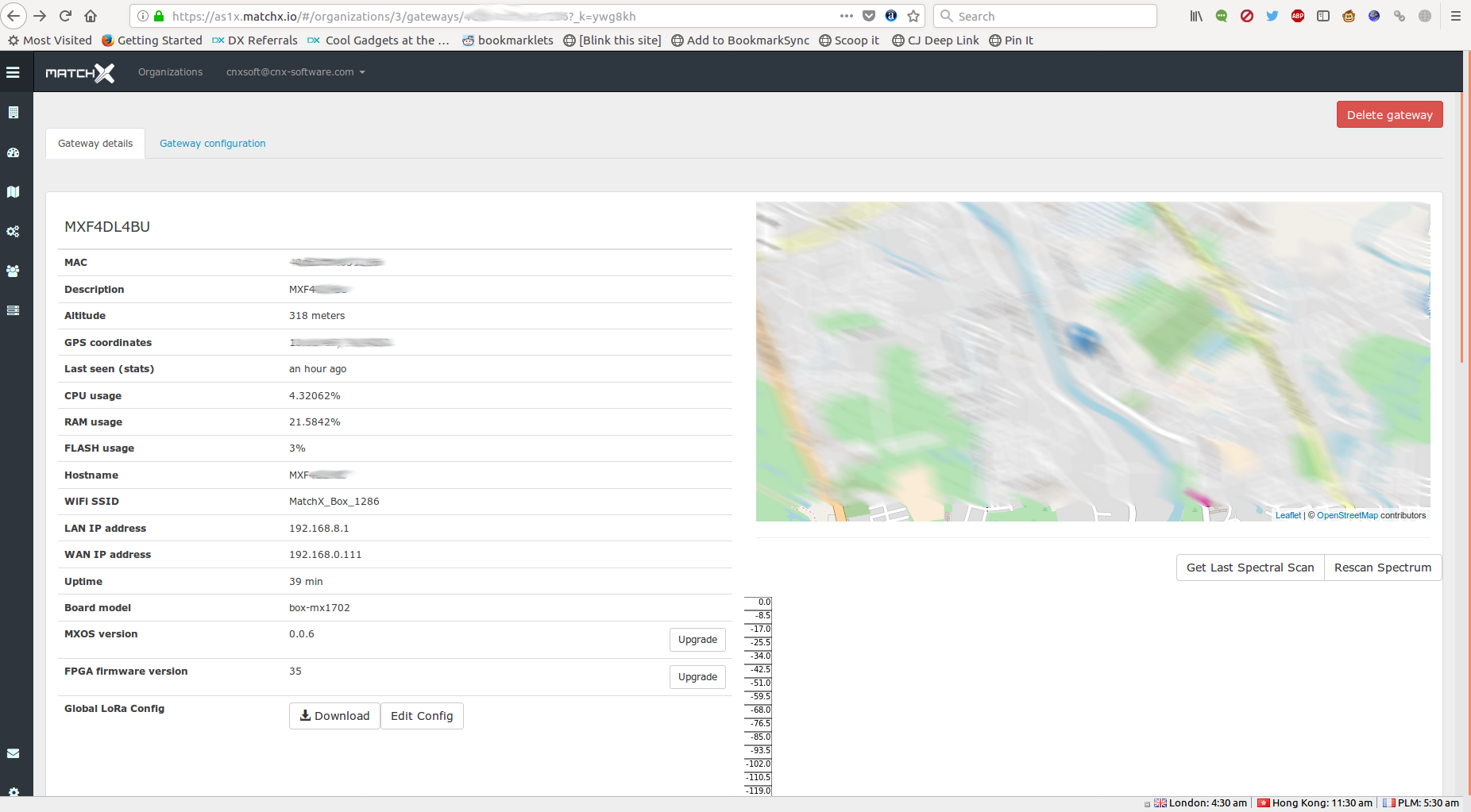
We just need to go to MatchX Cloud, specifically the Gateway details page, and click on Edit Config button to change the gateway part to connect to TTN (AS1 in my case) instead of MatchX Cloud server:
|
1 2 3 4 5 6 7 8 9 10 11 |
"gateway_conf": { /* change with default server address/ports, or overwrite in local_conf.json */ "server_address": "router.as1.thethings.network", "serv_port_up": 1700, "serv_port_down": 1700, "servers": [ { "server_address": "router.as1.thethings.network", "serv_port_up": 1700, "serv_port_down": 1700, "serv_enabled": true } ], |
Now click on Upload Config button, and the gateway configuration should be done. You’ll just want to note the MAC in the Gateway details windows, as it’s also the Gateway EUI that will be asked in TTN later on.
Setting Up The Things Network
Now let’s go to The Things Network website, sign-up for a free account, and go to the TTN Console. Click on Gateway, and register gateway.
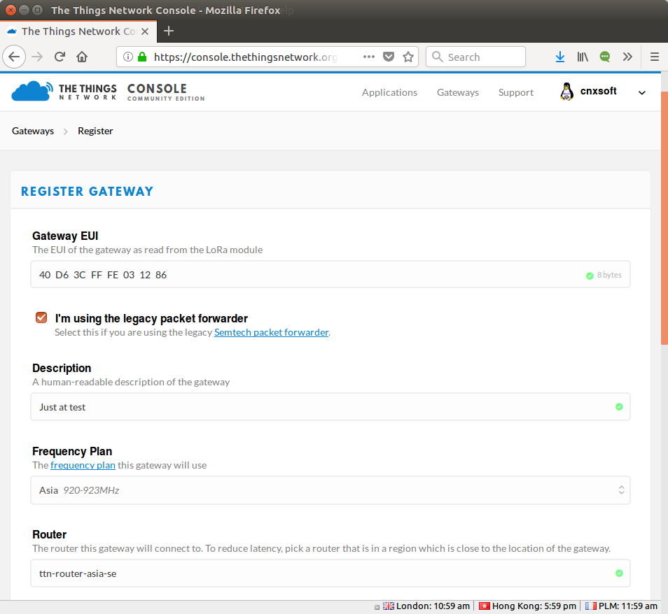
First tick “I’m using the legacy packer forwarder”, and paste the MAC from the gateway into “Gateway EUI” field, provide a description, select the frequency plans (Asia 920-923 MHz here), and select the router for your region.
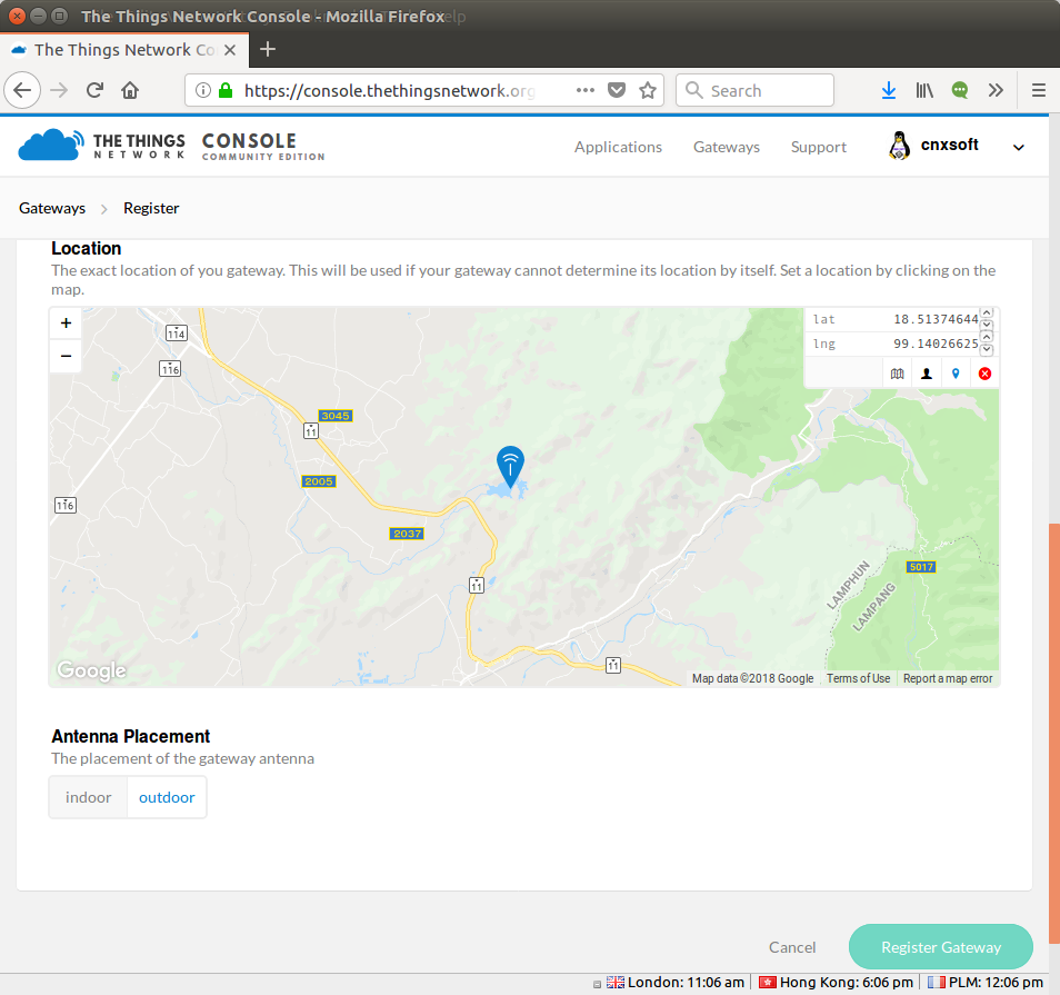
You could also indicate the gateway location, but for MatchBox gateway it’s not needed as it supports GPS, and finally select the antenna placement (outdoor or indoor), and click on Register Gateway.
Now go back the TTN Console main page, and click on Application, then add application.
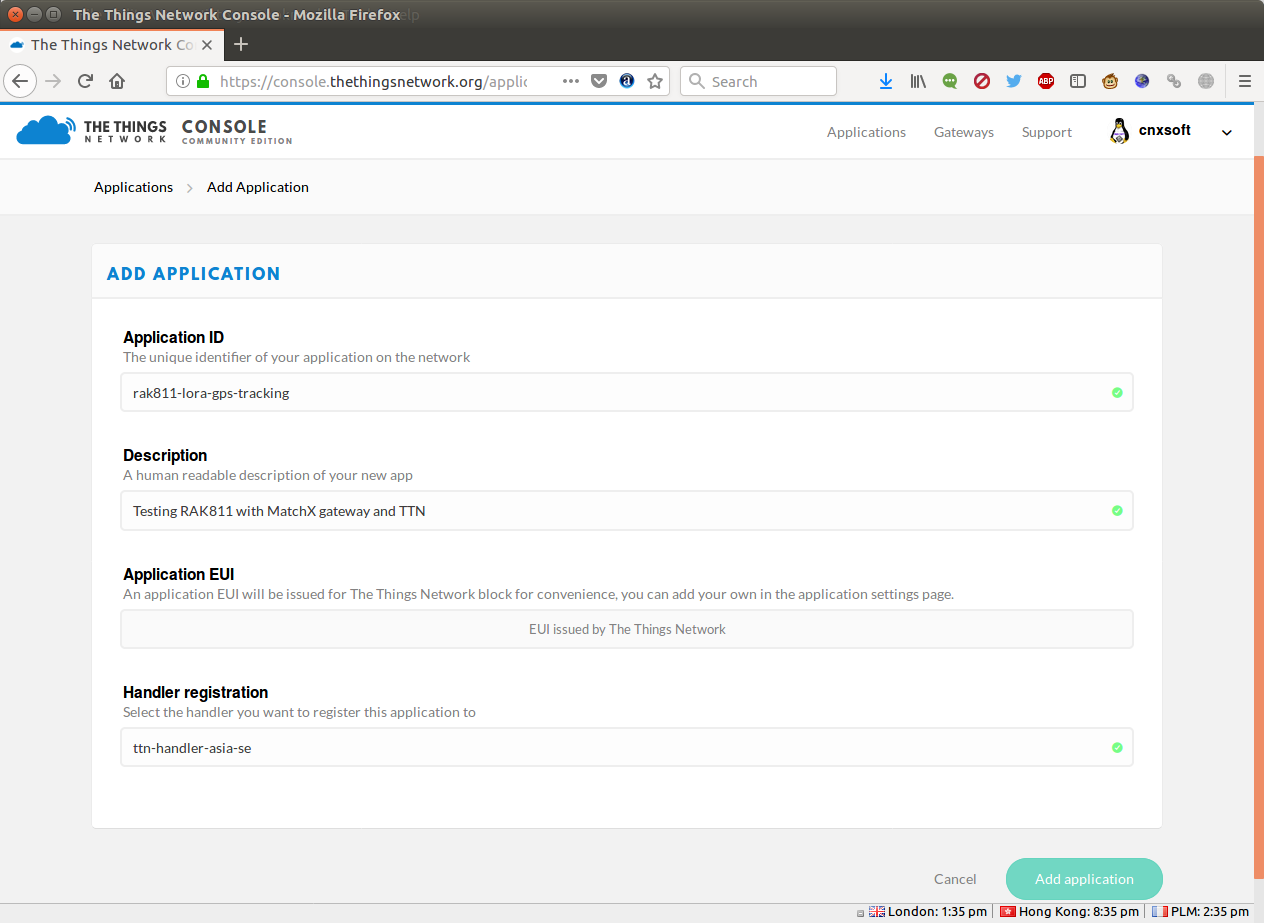
Fill an application ID, description, and handler registration of your choice, before clicking on Add application.
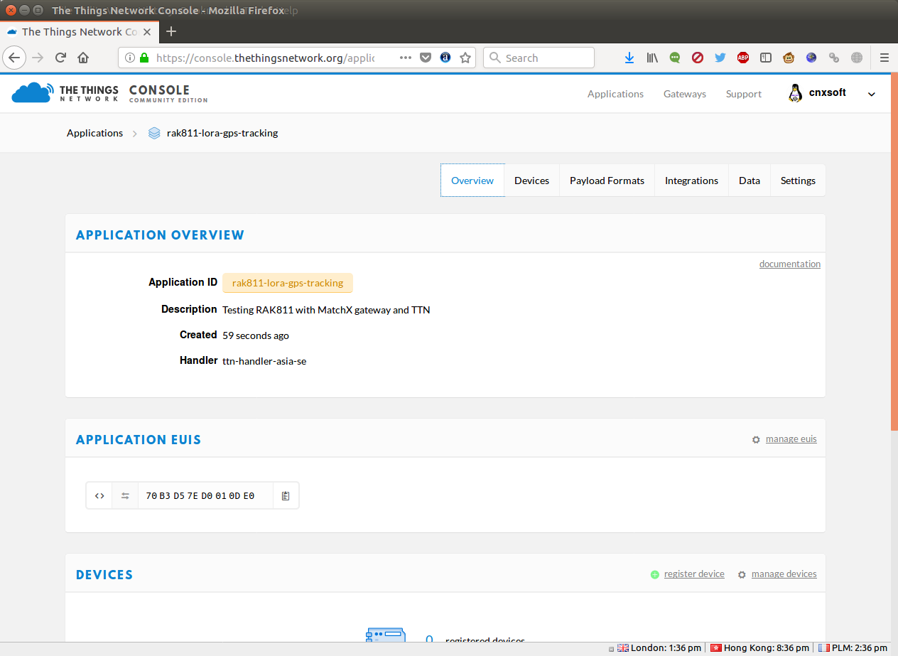
You should be redirected to the Application overview page, and you can now click on Devices in the top menu, and register device.
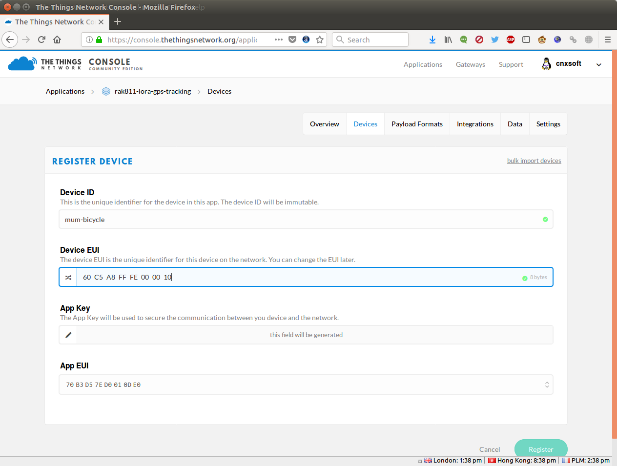
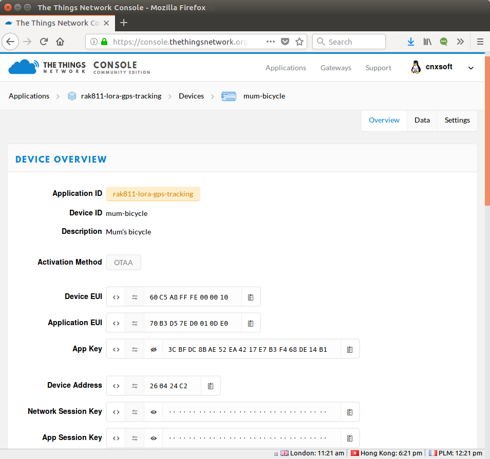
Give it a Device ID, as well as the Dev EUI we’ve configured in RAK811 node, and click on Register. Now go to the Device Overview page, and you’ll find th DevEUI, AppEUI, and AppKey values.
Configure RAK811 for The Things Networks
Now we can go back to the terminal console on RAK811 tracker to reconfigure with our new values
|
1 2 3 4 5 |
at+dev_eui=60c5a8fffe000010 at+app_eui=70B3D57ED0010DE0 at+app_key=3CBFDC8BAE52EA4217E7B3F468DE14B1 at+region=AS923 at+join_mode=otaa |
I found I had to erase the data, and reflash the firmware with Flash Loader Demonstrator before being able to update the values with AT commands, but YMMV. Let’s reset the board:
|
1 2 3 4 5 6 7 8 9 10 11 12 13 |
RAK811 BreakBoard soft version: 1.1.3 Selected LoraWAN 1.0.2 Region: AS923 OTAA: Dev_EUI: 60 C5 A8 FF FE 00 00 10 AppEui: 70 B3 D5 7E D0 01 0D E0 AppKey: 3C BF DC 8B AE 52 EA 42 17 E7 B3 F4 68 DE 14 B1 OTAA Join Start... Move Detected INT1 src:0x42 Move Detected INT1 src:0x50 Move Detected INT1 src:0x50 Move Detected INT1 src:0x50 OTAA Join Success [Debug]: latitude: 0.000000, longitude: 0.000000 , altitudeGps: -1 |
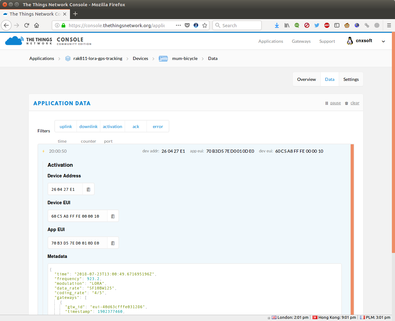
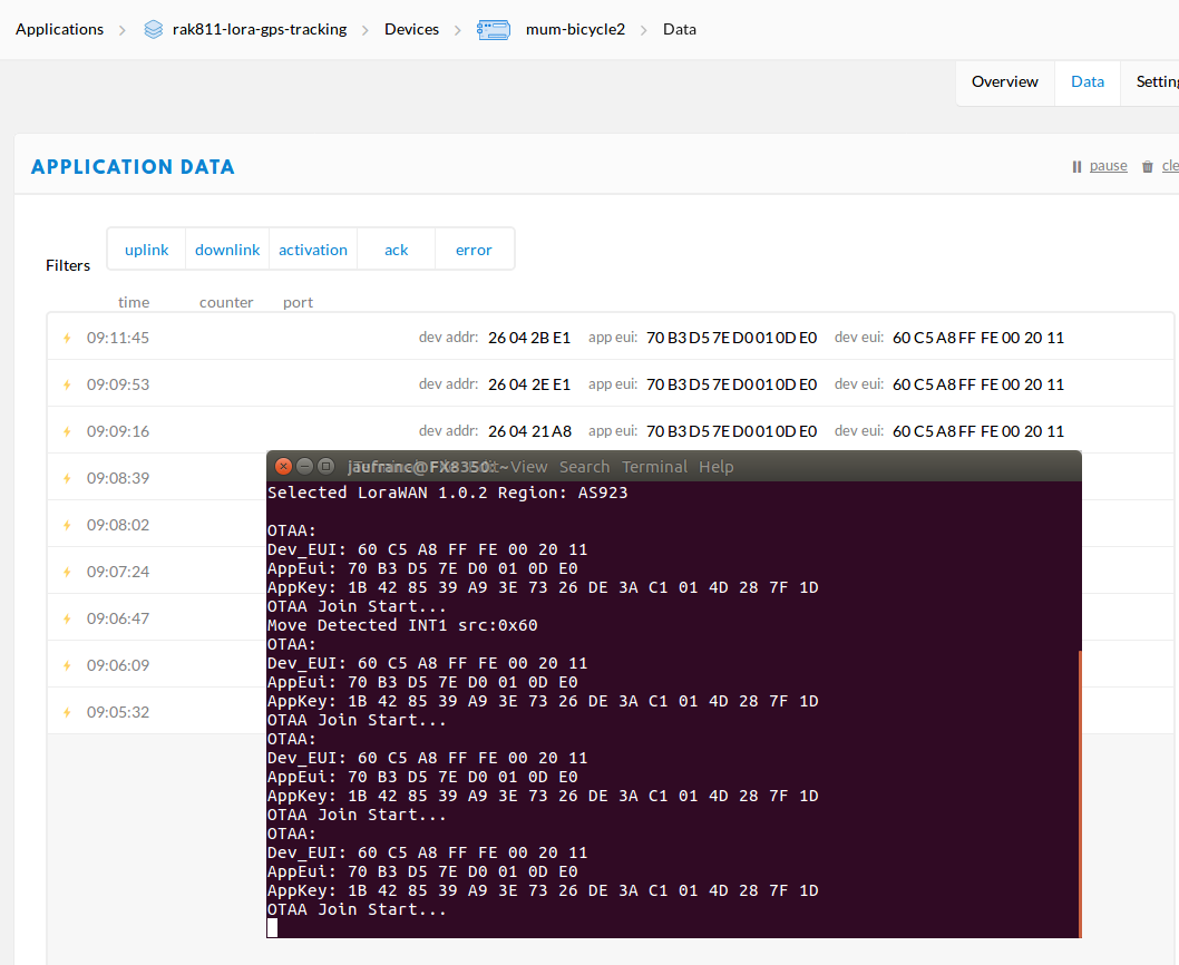
It looks good, we just need to wait for the GPS fix. In the meantime, we can find out if we received the join request from the device in TTN interface, using the Data tab of the device we’ve just configured.
Excellent. We now need to register the device with myDevices.com, as the service will handle Cayenne LPP data decoding, and show data in a pretty way.
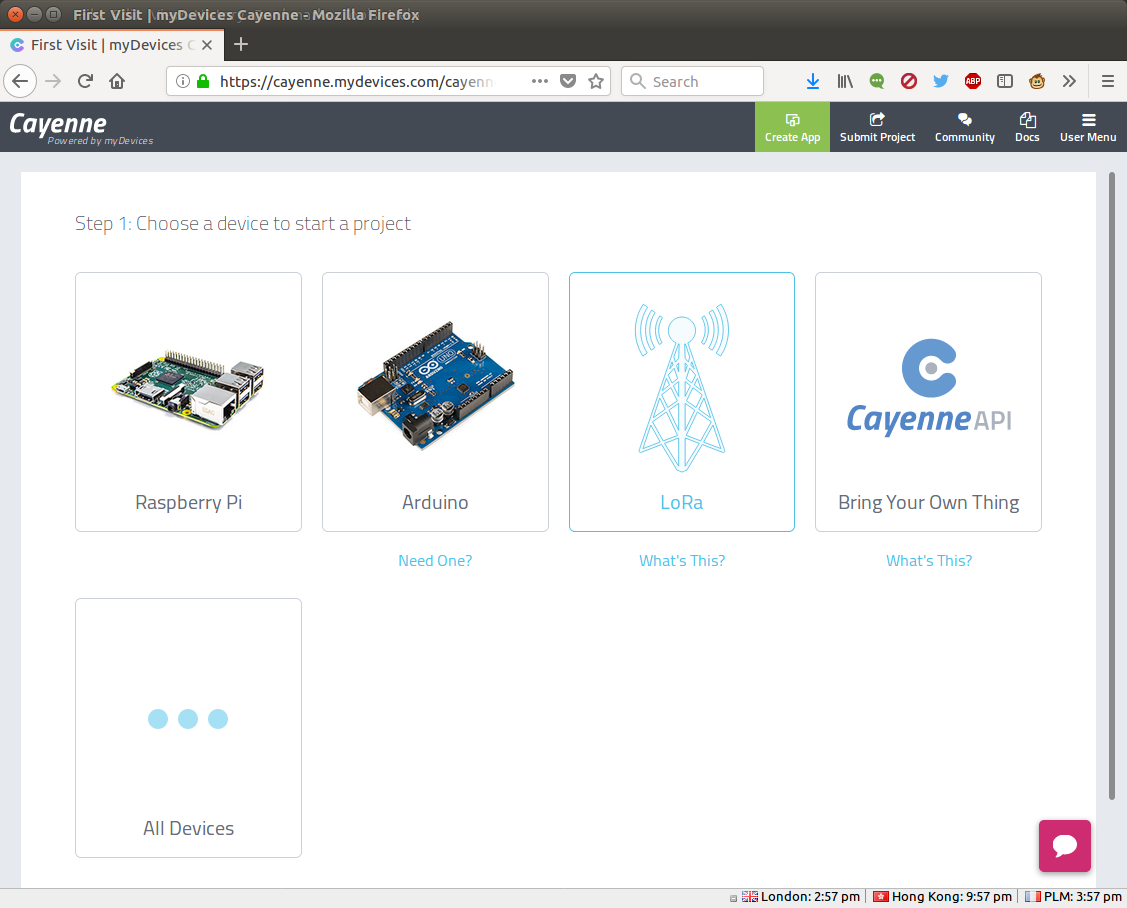
After you’ve signed-up to the free service, select LoRa in the dashboard.
Then The Things Network on the left side of the interface…
Now scroll down to select Cayenne LPP…
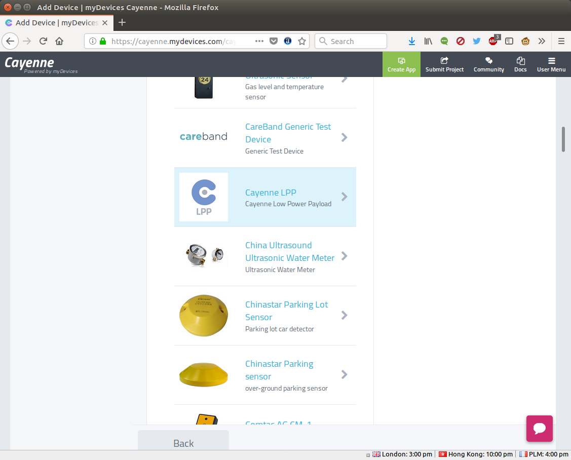
… and enter a name, your DevUI, and click on “Add Device”.
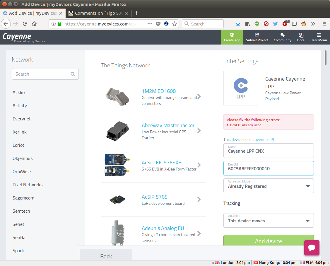
Nooooo! . The DevEUI is already taken… Damn. So I tried a few others until I found “60c5a8fffe002011” was unsued. I added that device, but I had to repeat the steps in The Things Networks and RAK811 serial interface to reconfigure everything with my new DevEUI…
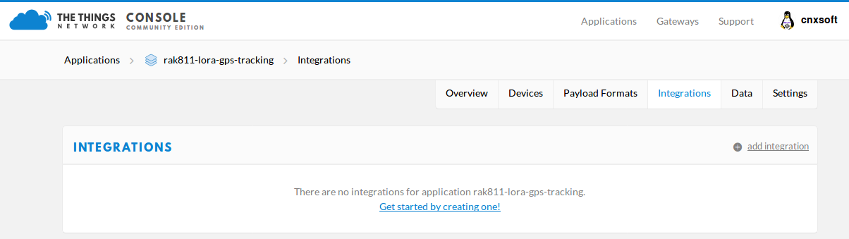
Configure Cayenne Integration in TTN
We’re not quite done yet, as we need to go back to TTN, click on Integration in the device dashboard…
 … select Cayenne icon, input a Process ID of your choice, and select default key in the Access Key field.
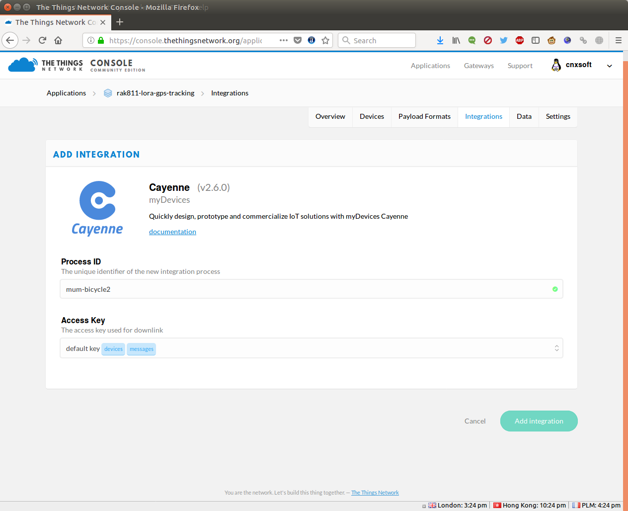 Click on Add integration button, go to Payload Formats, and select Cayenne LPP.
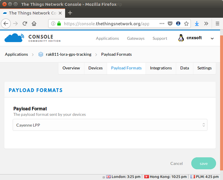
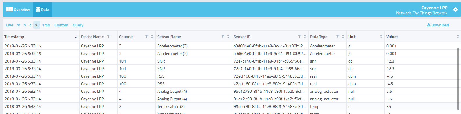
Click on Save, and after a few minutes, we should see a nice representation of temperature, accelerometer, and GPS data in Cayenne.
Still More Problems and a Workaround
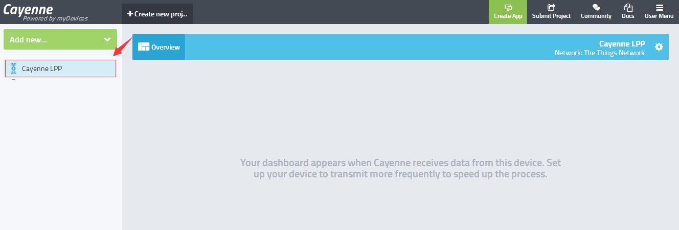
But a few hours later, I still got an empty dashboard 🙁 What is going on?
I can see some packets in TTN, but the serial console shows some troubles with OTAA Join. So appears RAK811 can send a join request to the gateway, which then forward it to The Things Netwokrs, but somehow it does not get a reply. I tried to change MatchX Gateway global_conf.json with the one provided by TTN for AS1 (Asia 1 – 920 – 923 MHz), but still no luck.
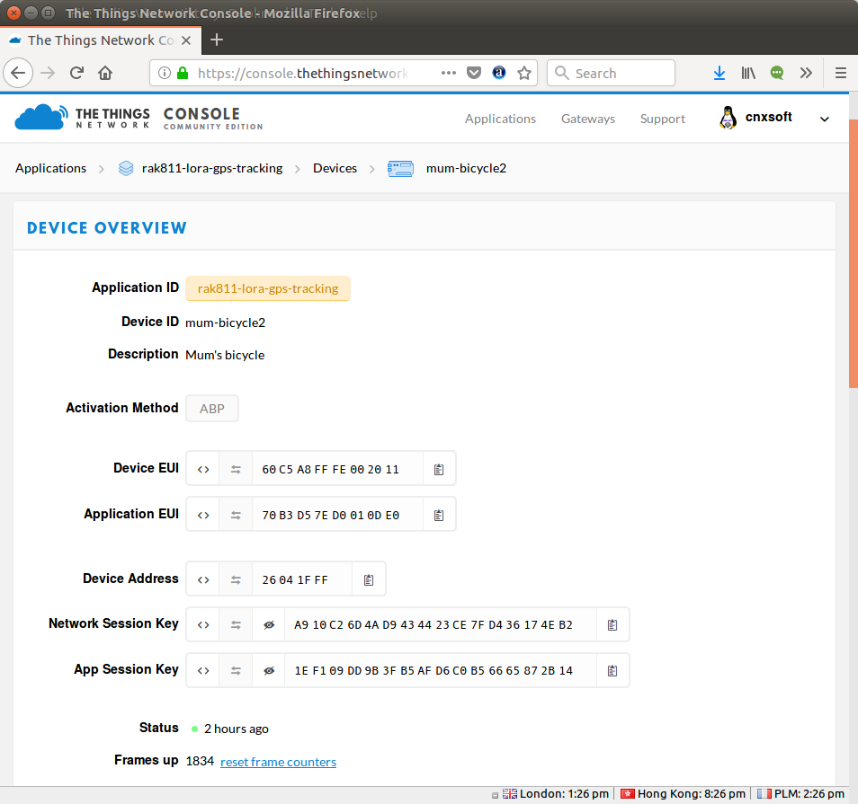
Finally, the guys at Rak Wireless helped me out via TeamViewer sessions, and found a “solution” by changing the Activation Method from OTAA to ABP join in TTN.
and pasting the relevant AT commands in RAK811 serial console.
|
1 2 3 4 5 6 7 |
at+dev_eui=60C5A8FFFE002011 at+app_eui=70B3D57ED0010DE0 at+dev_addr=26041FFF at+nwks_key=A910C26D4AD9434423CE7FD436174EB2 at+apps_key=1EF109DD9B3FB5AFD6C0B56665872B14 at+region=AS923 at+join_mode=abp |
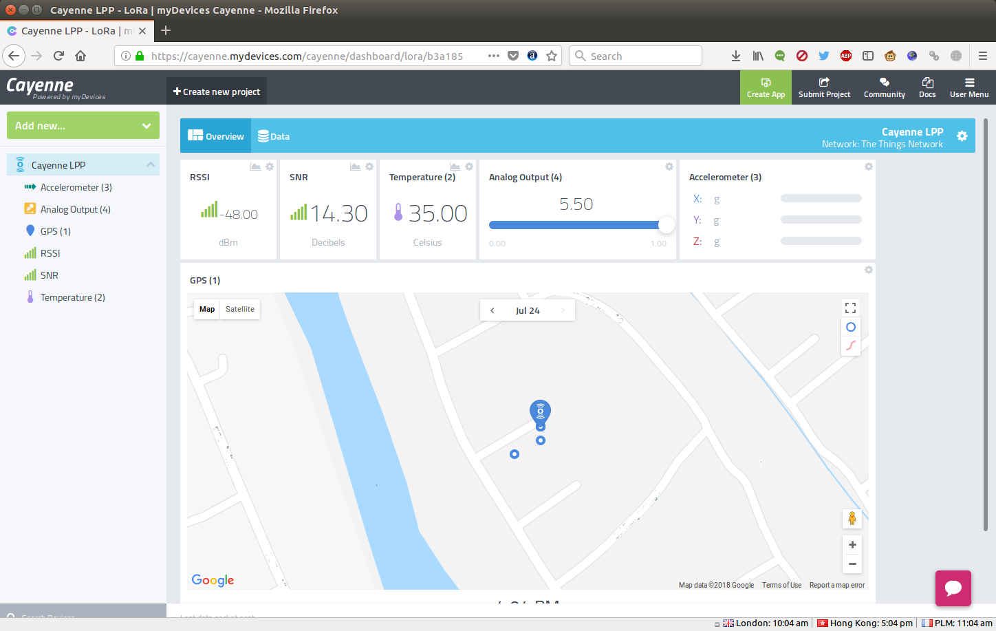
Reset the board, and after a few seconds I started to get RSSI and SNR data in Cayenne LPP dashboard, and within a few minutes the GPS data was aso retrieve and I could see RAK8711 LoRa tracker position in mydevices.com
That was not exactly trouble-free experience, but I was happy to finally manage it. Rak Wireless thought the issue with OTAA might be a timing issue. MatchX on their side considerered that it could be a problem with power tables:
A potential problem can be with the power tables. When Server wants to send the message to the end node, it specifies the requested power RF level. Gateway takes this power level and subtracts the antenna gain (specified in global_config, 2.5db in our case but 0.5 is dropped and only 2db is subtracted) to compensate for used antenna. Than it looks for the entry in its LUT power table with this particular power to configure its internal amplifiers. If it can’t find the required power level the message is dropped. Our global_config is configured to be complaint with LoRa regional parameters 1.0 and we are going to update to version 1.1 somewhere in near future. TTN server may be configured differently though. We haven’t tried TTN servers for this region.
Nevertheless, I have not investigated this part yet, as I wanted to finished this review pretty quickly, since I’ll soon have to remove the gateway due to personal reasons.
Running, Driving and Walking Around
Now that I had everything up and working, I wanted to test the node outside the home to see the range I got. My first test was a 3km evening run keeping everything in place with a belt.
![]()
But I soon found out RAK811 automatically turn itself off. It happens sometimes when running on battery, but looks a bit random. I’m not sure it’s a typical problem since I damage the board as I fell is an earlier test at home, and damaged some pins.
Nevertheless, I did not get any data that evening, but next morning, I drove the car out. I first drove a few dozen meters, and check the location of the tracker was indeed updated before losing WiFi connection (I don’t use cellular data).
![]() Good! The location was properly updated with reasonable accuracy (4 to 5 meters off). Then I slowly drove to another location with WiFi about 500 meters (line of sight), and connected to check if the location was updated every minute as it should, and nothing in myDevices dashboard. So I connected RAK811 to my laptop to check it got GPS data in the serial console, and sure enough it did. I drove back, and when I was home I could not further updated. myDevices dashboard would not be updated anymore even though some messages were received in TTN dashboard.
Good! The location was properly updated with reasonable accuracy (4 to 5 meters off). Then I slowly drove to another location with WiFi about 500 meters (line of sight), and connected to check if the location was updated every minute as it should, and nothing in myDevices dashboard. So I connected RAK811 to my laptop to check it got GPS data in the serial console, and sure enough it did. I drove back, and when I was home I could not further updated. myDevices dashboard would not be updated anymore even though some messages were received in TTN dashboard.
Later that day, I went for a walk to the local market around 500 meters away in a straight line, and kept monitoring packets in TTN.
I think I left home around 10:20, and I was in an indoor shop at 10:32 according to the receipt. In an ideal world, I should have received messages every minutes, but there was a 6 minute period during which TTN did not receive any messages at all (10:25 to 10:31). The same packet loss did not occur on the way back, with just two messages lost. Sadly, still nothing in myDevices dashboard.
The funny thing is that I’m writing those words, I could see data in myDevices today (another day) up to 17:33.
The time is now 20:00. RAK811 board is still running, I have not touched it, but since no new data have been received for 2 hours and a half. Locals told me we have ghosts here, so that must be why 🙂 More seriously, I suspect the problem that occurred with OTAA, maybe resurfacing with ABP randonly. So maybe its indeed a timing issue, or a problem with a specific frequency.
My first experience with LoRa / LoRaWAN was not exactly painless, and I still have much too learn. For example, I’ve yet to look at power consumption / battery life matters since I struggled so much to make it work. But at least it was a good learning experience, as I know better understand how this works, and how each part from hardware to the cloud integrates together.
If you’re interested in getting the hardwareI played with you can get MatchBox LoRa gateway on MatchX website for 350 Euros, and RAK811 LoRa tracker for about $50 shipped on Aliexpress.

Jean-Luc started CNX Software in 2010 as a part-time endeavor, before quitting his job as a software engineering manager, and starting to write daily news, and reviews full time later in 2011.
Support CNX Software! Donate via cryptocurrencies, become a Patron on Patreon, or purchase goods on Amazon or Aliexpress


Finally I’ll just drop a message I got from Rak Wireless a little while ago about power consumption and HW changes: But based on current design we will ship to you, if you want to calculate the power consumption: Tx current: 120mA, tramission time you can base on 100ms Standby current: 5.6mA Sleep mode: 200uA Here is our reply in TTN to get more insight: https://www.thethingsnetwork.org/forum/t/rak811-tracker-board/11006/279 —————————————————– After seriously read the discussion by this thread and rak forum, we collect the suggestion and decide to optimize the rak811 tracker design as following: The R1/C1 pin of GPS power switch chip… Read more »
Apparently they increased the price from $29.99 (as you reported) to a whopping $99. Do you remember when you last checked the price? From the transaction history it looks like they haven’t sold anything since August…