SunFounder’s Raspberry Pi UPS Power Supply is a complete UPS kit for the Raspberry Pi 3/4 Model B/B+ with a PiPower board, a 2,000 mAh battery, and all accessories requires for the assembly. It also works with other Raspberry Pi-sized boards that support 5V DC input such as Banana Pi BPI-M5, Libre Computer ROC-RK3328-CC, and other similar SBCs.
Many years ago, I bought a Raspberry Pi battery pack for review hoping that it would also work as a UPS, but it was not perfect as the board would sometime reboot during power failure simulations. Since then, there have been many UPS kits launched to the market, but I didn’t try any so far, so when SunFounder contacted CNX Software to review their “Raspberry Pi UPS Power Supply”, I took the opportunity, and I will report my finding in this review.
Raspberry Pi UPS Power Supply key features
- UPS module output – 5V/3A via USB Type-A port
- Battery charge – up to 5V/2A MAX
- Can power the Pi and charge the battery simultaneously
- Power Supply – 5V/3A via USB Type-C port
- Battery – 7.4V/2,000mAh. battery life: 3-4 hours
- Battery protection – Overcharge/discharge protection, balance charging, and overheating protection.
- Misc
- On/Off switch
- Power LED
- Charging LED
- 4x battery-level LEDs
- Header to monitor battery
- Dimensions – 90 x 56 x 24 mm
“PiPower” kit unboxing
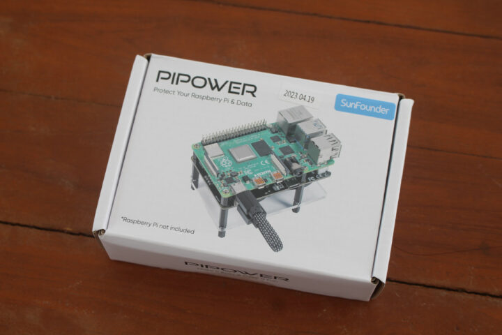
While the website calls the kit “SunFounder Raspberry Pi UPS Power Supply”, the kit I received shows PIPOWER branding.
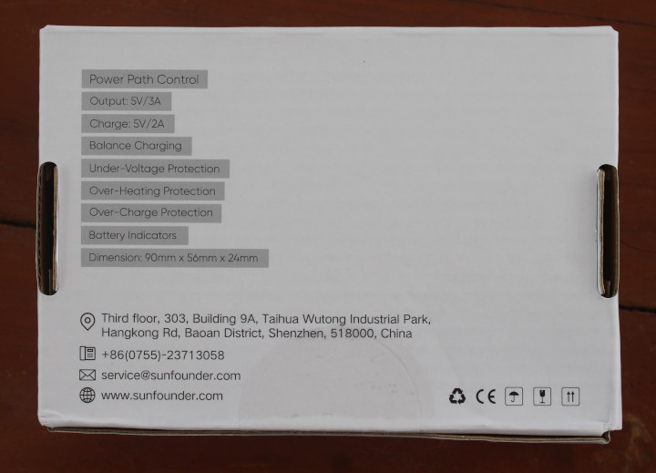
The bottom side of the package lists basic specifications and some contact information.
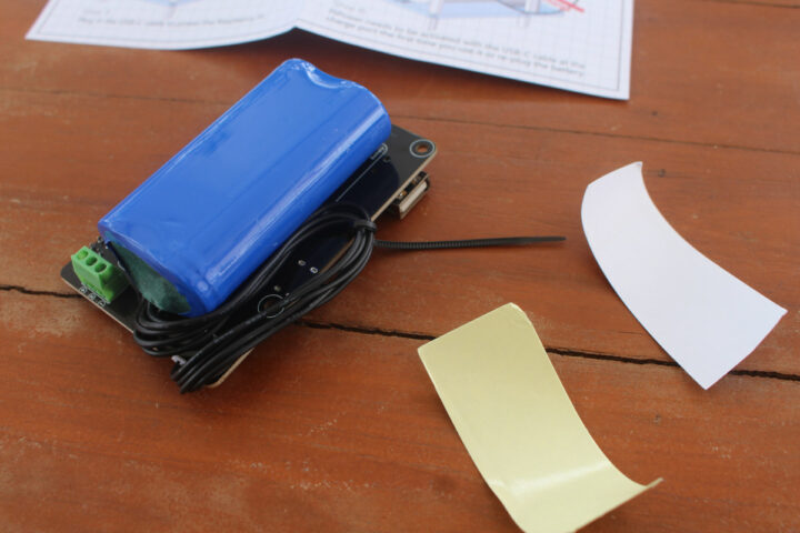
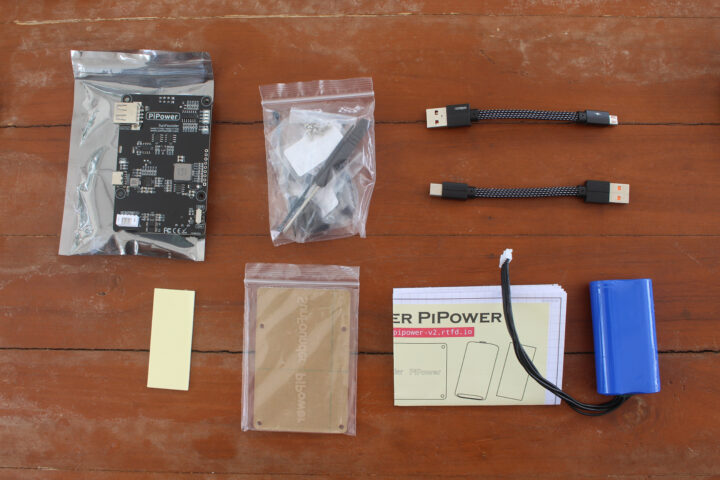
The kit is comprised of the PiPower board, a screwdriver, some screws, standoffs, and cable ties, as well as short USB-C and micro USB cables, double-sided adhesive tape, an acrylic plate, a quick start quide, and the battery itself.
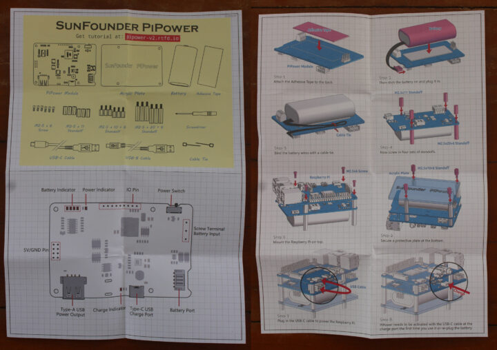
The quick start guide lists the accessories in the kit, describes the main features of the PiPower board, and explains how to assemble the UPS kit and mount it to the Raspberry Pi board. It also points to the online documentation.
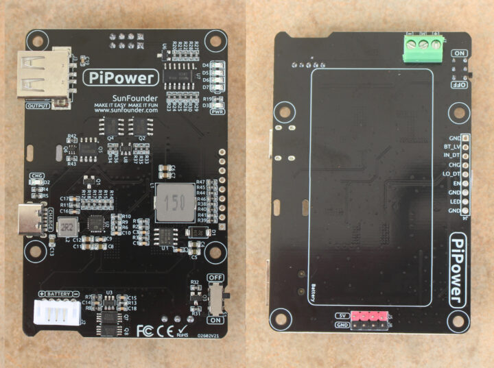
The PiPower is based on the IP2326 lithium battery charging IC. The bottom side comes with an area for the battery, a 3-pin terminal for battery input, an on/off switch, a GPIO header for battery monitoring, and headers providing access to 5V and GND to potentially power external devices.
The GPIO provides the following signals
- GND – Ground
- BT_LV – Battery voltage pin. The voltage of this pin is equal to 1/3 of the battery voltage.
- IN_DT – Input detect pin. Used to determine if there is USB power input, if so, this pin outputs high.
- CHG – Charging status indication pin. This pin is high when charging.
- LO_DT – Low voltage status pin. When the voltage is high enough, this pin is low, but when low battery voltage is detected, this pin is high.
- EN – Switch signal pin. The EN pin can be connected to an external switch, so the PiPower is powered off when the pin is set to 0. The EN pin is only active when the PiPower is turned on.
- GND – Ground
- LED – Power indicator pin. Output 5V at power on. Note a resistor must be added when connecting an external LED.
- GND – Ground
BT_LV level requires an analog input on the host, but there’s not on the Raspberry Pi. This could be resolved with an additional ADC chip, or by using another compatible SBC with a spare analog input pin. The ODROID-C4 board would be a candidate as to comes with two analog inputs that support up to 1.8V which should be enough if the pin outputs a third of the battery voltage. Update: I forgot the battery voltage is 7.4V, and not 3.7V, so the 1.8V level on the ODROID-C4 analog inputs would not be sufficient for 7.4/3 = ~2.47V. Update 2: The ODROID-C4 only supports 5.5V to 17V DC so it would not be supported by the UPS kit. See comments section.
Raspberry Pi UPS Power Supply assembly
Let’s assemble the kit. We’ll first need to place the adhesive tape on the location of the battery, install the battery on top and connect it to the board before finally doing some cable management by using a cable tie to attach the cable to the board.
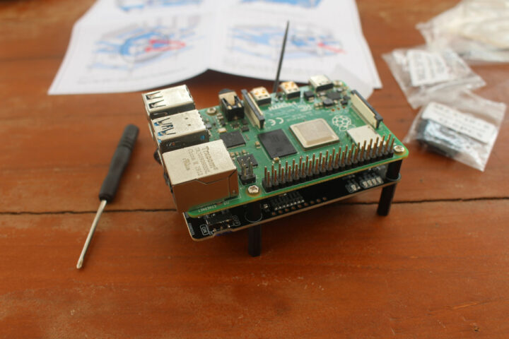
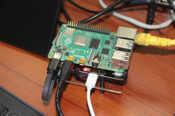
We can now mount a Raspberry Pi 4 SBC on top of the PiPower board using the provided standoff and screws.
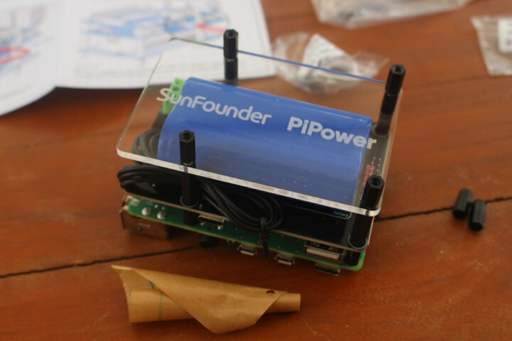
The next step is to install the acrylic plate under the battery. It looks optional, but it will make sure the battery stays in place in case the adhesive tape becomes less sticky over time.
The final step is to connect the provided USB Type-A to Type-C cable between the output board of the PiPower board and the power input of the Raspberry Pi 4 board.
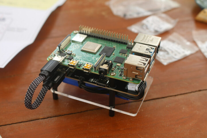
We could also have soldered a header for battery monitoring, but that’s something we’ll try later on.
“Dumb” mode testing
But first, we will review the SunFounder Raspberry Pi UPS Power Supply in what I call “Dumb” mode without battery monitoring.
I made sure the PiPower was turned off to fully charge the battery. You’ll see the red charging LED turn on when charging, and turn off when the charge is complete. It took around one hour, but that’s because there was already some charge in the battery. Subsequent tests after a full discharge took around 2h15 for a full charge. Note that I used the official 5V/3A power supply from the Raspberry Pi Foundation.
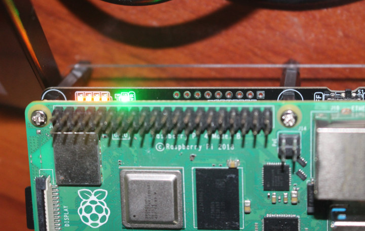
We can now slide the power switch to turn the PiPower and Raspberry Pi 4 on. The power LED turns green, and we can also see the four battery-level LEDs are all lit up.
I then tested discharge time during idle with a display and Ethernet connected to the SBC. The first one failed because it lasted longer than expected and I fell asleep before the battery was discharged… On my second try, I found the battery can last around 5h30 on a charge. The charging level LEDs can be confusing as I noticed the first one would turn off after almost 3 hours which should represent around 75% capacity, the battery will only last for around 2h30 hours extra. My electricity provider has a tendency of doing maintenance work between 8:30 and 16:30, sometimes taking the full eight hours, and 5h30 is not enough, but maybe implementing some of the power-saving techniques for the Raspberry Pi Zero 2W could help a great if needed.
I repeated the discharge test after a full charge under a heavy load with the stress -c 4 command and the battery lasted 3 hours as mentioned in the specifications. I check the LEDs as well, and the first LED turns off after 1h30, and the second after 1h15 extra, and the next time I check (about every 15 minutes), the battery was fully discharged.
Each time I turn on or off the USB power input, the low voltage signal will show for about one or two seconds in Raspberry Pi OS. I’d assume this is normal because of the time it takes to detect the power drop on the USB port, before switching to the battery. This reminds me that I mostly had an issue with my previous battery pack when a cooling fan was connected or a USB hard drive due to the higher power consumption. So I tried to simulate power failure with a USB hard drive again under various scenarios:
- Pi 4 idle with USB HDD – 10 tries, no issues
- Pi 4 stress test with USB HDD – 10 tries, no issues
- Pi 4 stress test with iozone testing the USB HDD – 10 tries, no issues.
So SunFounder PiPower UPS kit works much better than the solution I tried 7 years ago, as the switch between USB and battery power happens quickly enough even until high power load scenarios.
PiPower battery monitoring
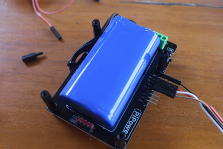
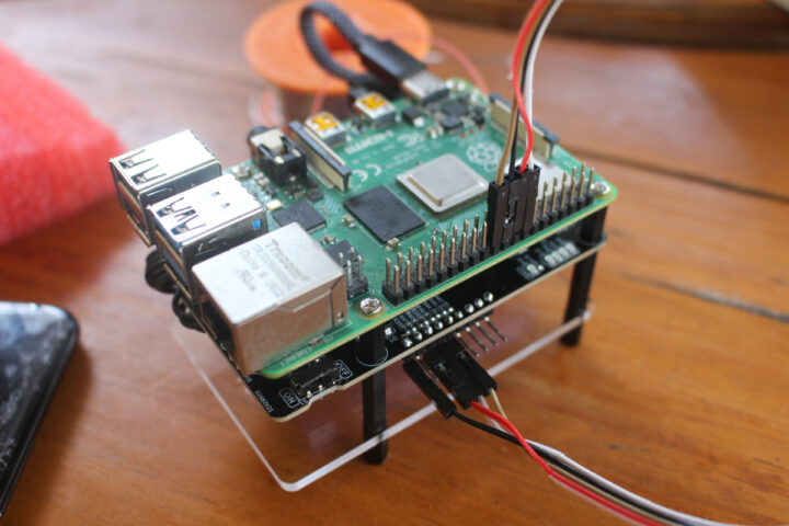
Let’s solder a GPIO head to the PiPower board since it has battery monitoring pins. We’ll use the LO_DT pin to detect the battery’s low voltage status, CHG to detect whether the battery is charging, and the IN_DT pin to check whether the power is connected. It’s also possible to check the battery level with the BT_LV pin, but this requires an additional ADC chip, and I’ll just work with the hardware I have on hand. You can check some example UPS projects on GitHub if you want to add an ADC to get the battery level.
The PiPower board already has resistors for the pin we are going to use, so we can connect the pin directly to the Raspberry Pi board with jumper cables:
- IN_DT to GPIO 23
- CHG to GPIO 24
- LO_DT to GPIO 25
- GND to GND
I could not find any code sample/script in the documentation, and SunFounder confirms they had not provided any such script for the script. So I wrote a simple Python script to print out the battery status in a terminal:
|
1 2 3 4 5 6 7 8 9 10 11 12 13 14 15 16 17 18 19 20 21 22 23 24 25 26 27 28 29 30 31 32 |
!/usr/bin/python3 import RPi.GPIO as GPIO import time IN_DT = 23 CHG = 24 LO_DT = 25 GPIO.setmode(GPIO.BCM) GPIO.setup(IN_DT, GPIO.IN) GPIO.setup(CHG, GPIO.IN) GPIO.setup(LO_DT, GPIO.IN) while True: if GPIO.input(IN_DT) == 1: print('USB Power detected') else: print('No USB power. Power failure?') if GPIO.input(CHG) == 1: print('Battery is charging...') else: print('Battery is not charging...') if GPIO.input(LO_DT) == 1: print('Low battery level detected!\n') else: print('The battery has sufficient charge\n') time.sleep(10) GPIO.cleanup() |
This is what it looks like while the battery is charging:
|
1 2 3 4 5 6 7 8 |
pi@raspberry-pi:~ $ ./pipower.py USB Power detected Battery is charging... The battery has sufficient charge USB Power detected Battery is charging... The battery has sufficient charge |
when it is fully charged:
|
1 2 3 4 5 6 7 |
No USB power. Power failure? Battery is not charging... The battery has sufficient charge USB Power detected Battery is not charging... The battery has sufficient charge |
when the USB power supply is disconnected from the board:
|
1 2 3 4 5 6 7 |
No USB power. Power failure? Battery is not charging... The battery has sufficient charge No USB power. Power failure? Battery is not charging... The battery has sufficient charge |
So it’s all good for USB power input and charging detection. You may want to edit the code to send an email or notification when a power failure occurs, and possibly turn off some services as needed.
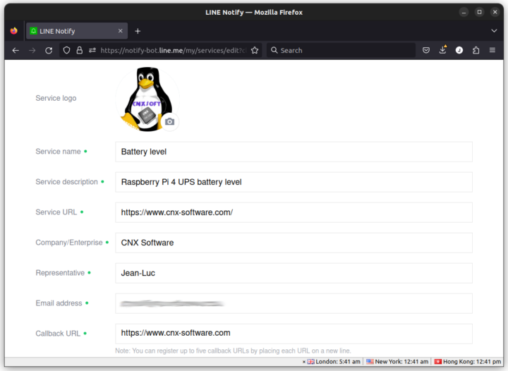
For low battery level detection, I decided to register to LINE Notify service instead, so that I can get notified when the battery level is low in my smartphone and/or smartwatch.
After having set up LINE Notify and gotten an access token, I modified the Python code to send a LINE notification once a low battery level is detected:
|
1 2 3 4 5 6 7 8 9 10 11 12 13 14 15 16 17 18 19 20 21 22 23 24 25 26 27 28 29 30 31 32 33 34 35 36 37 38 39 40 41 42 |
#!/usr/bin/python3 import RPi.GPIO as GPIO import time import requests #pin definitions IN_DT = 23 CHG = 24 LO_DT = 25 #LINE Notify parameters url = 'https://notify-api.line.me/api/notify' token = '<LINE_access_token_here>' headers = {'content-type':'application/x-www-form-urlencoded','Authorization':'Bearer '+token} GPIO.setmode(GPIO.BCM) GPIO.setup(IN_DT, GPIO.IN) GPIO.setup(CHG, GPIO.IN) GPIO.setup(LO_DT, GPIO.IN) while True: if GPIO.input(IN_DT) == 1: print('USB Power detected') else: print('No USB power. Power failure?') if GPIO.input(CHG) == 1: print('Battery is charging...') else: print('Battery is not charging...') if GPIO.input(LO_DT) == 1: print('Low battery level detected!\n') msg = 'Battery level low!' r = requests.post(url, headers=headers , data = {'message':msg}) print (r.text) else: print('The battery has sufficient charge\n') time.sleep(10) GPIO.cleanup() |
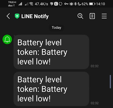
I then started the discharge at 21:14 with the Raspberry Pi 4 idle, and I got recurring notifications in LINE starting at 02:32. My phone was in silent mode, but my new smartwatch was not, and it would vibrate every few seconds… So sleepy me disabled WiFi and cellular data on my phone to stop this madness in the middle of the night! 🙂 Anyway, that meant it took 5h18 before getting that low battery level notification, which confirms my initial testing, but with more accurate timings.
For the next test, I wanted to check how long it would take for the battery to charge upon resuming from a power failure and starting a heavy workload (stress). So I modified the code to send a notification once the battery is charged (i.e. not charging anymore):
|
1 2 3 4 5 6 7 8 |
if GPIO.input(CHG) == 1: print('Battery is charging...') else: print('Battery is not charging...') msg = 'Battery is not charging anymore' r = requests.post(url, headers=headers , data = {'message':msg}) print (r.text) time.sleep(50) |
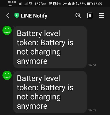
This code does not 100% guarantee the battery is charged when “not charging” is detected, since it would also be triggered when the USB power input is down, but that will do for this test. It does take a while to charge the battery under heavy loads since I started charging and running the command “stress -c 4” at around 08:33 and I noticed the four charge-level LEDs were lit when I checked at around 11h30. But after waiting until 15:33 (or 7 hours), and still not having received any notifications, I decided to stop the stress test, and after a few more minutes I finally got the “not charging” notifications.
Conclusion
The “PiPower” Raspberry Pi UPS Power Supply is an inexpensive UPS solution that is easy to use and works well, and it’s a no-brainer if all you want is a solution that keeps your Raspberry Pi running even in the case of a power failure. It does offer battery monitoring pins for battery level (analog), low battery level detection (digital), USB power input detection, and charging detection, but some (easy) soldering is required, and the company does not provide a script or plugin (e.g. to display battery status in the notification bar on Raspberry Pi OS), so you have to write the code yourself.
I’d like to thank SunFounder for sending their “Raspberry Pi UPS Power Supply” for review. It can be purchased for $25.99 on their online store with 10% off for first buyers, and on Amazon for $29.90 with also an extra 10% discount when ticking a box.

Jean-Luc started CNX Software in 2010 as a part-time endeavor, before quitting his job as a software engineering manager, and starting to write daily news, and reviews full time later in 2011.
Support CNX Software! Donate via cryptocurrencies, become a Patron on Patreon, or purchase goods on Amazon or Aliexpress




Heavy load?
Yes
The price is quite reasonable for the specs. It’s great they went to 7.4V, it provides more efficient conversion to 5V that boosting a single 3V cell when it starts to get depleted. However it requires a balancing charger, otherwise over time the one battery will be fully charged when the other one is not, leading to poorer overall capacity, and balanced chargers are not always great at high charging currents because they can only absorb a limited current (e.g. 50mA). It would be nice to find what they opted for on this one. Another point, if the capacity is… Read more »
I left the kit turned on last night with the Raspberry Pi idle, and the charging LED was still on. The charge could only complete after I turned the Raspberry Pi and PiPower off. That’s odd…
it’s possible that both the DC-DC and the input are sent to the output in parallel and that it depends which one has the higher voltage. If it’s the DC-DC converter, then it will always experience a tiny consumption that prevents it from reaching an exact 100% charge, but it’s possible that in practice it is charged. A good test is to unplug everything and plug the charger again to see how long it takes to complete the charge. If you see that in 1-5 minutes everything is finished, you’ll know that in practice the battery was fully charged anyyay.
Yes, I don’t think it took even one minute before the charge LED turned off.
But that means “fully charged” detection is not reliable. Not a big issue IMHO.
That’s really quite common in my experience. And definitely annoying as well 😉
They state the Odroid C4 is also supported. Is there any hint, since the C4 is not powered by USB. Are they confused with the XU4 or are they trying to feed 5V to the 40p header directly? Or are they feeding 5.5V++ through the 6-13V connection?
You’re right. This completely escaped me. They must have looked at the ODROID-C4 form factor, and the PiPower kit can be installed on it, but it’s clearly not compatible.
If there’s a power outage on my network and the ups batteries start supplying energy to the Pi, once the network power restore, will the ups automatically switch back the mode so it stops consuming energy from the batteries to use the power from the network?
Once the power comes back up, the system will draw power from the mains to power the board and charge the battery until it is fully charged.