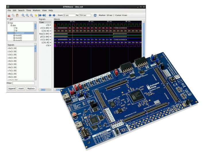
Cologne Chip’s “Integrated logic analyzer” (ILA) project is an open-source Verilog implementation of a logic analyzer running on the company’s GameMate A1 FPGA and designed to capture internal signals.
When we first covered the GameMate A1 FPGA we noted Cologne relies on the open-source Yosys framework coupled with a proprietary, but free-of-charge, place & route tool contrary to most other FPGA vendors that only offer closed-source proprietary development tools. The German company has now released the GateMate integrated logic analyzer project to help customers debug their FPGA designs.

The project includes the digital circuit of the ILA designed in the hardware description language Verilog and a Python program (ILA Control Program) used to configure the configuration of the ILA from the design under test (DUT) and provide an interface with the user during the debugging process. The user will also need a GateMate FPGA toolchain and GTKWave open-source program to visualize the captured waveforms, as well as his/her own FPGA design for the GameMate FPGA or one of the example projects (“Blink” or 8×8 LED matrix) can be used instead.

The “Blink” sample mentioned here refers to a PLL whose output clock signal synchronously increments a 25-bit register and the said register has its highest-order bit connected to an LED. The red line in the screenshot above shows when the bit switches from 0 to 1 and the LED is turned on.
The project has been tested on the GateMate A1 FPGA evaluation board, but it should work with custom-designed GateMate FPGA boards as long as they meet some requirements:
if customer hardware is used, please note that the ILA requires a USB interface between the computer and the GateMate FPGA. The FPGA ultimately uses an SPI interface to communicate with the PCB circuitry. The USB-to-SPI adapter can either be built on the customer PCB or the GateMate FPGA Programmer can used and connected to the FPGA.
You’ll find the Verilog implementation, sample projects, the Python program, and detailed documentation on the project page on GitHub.
Thanks to Dave for the tip

Jean-Luc started CNX Software in 2010 as a part-time endeavor, before quitting his job as a software engineering manager, and starting to write daily news, and reviews full time later in 2011.
Support CNX Software! Donate via cryptocurrencies, become a Patron on Patreon, or purchase goods on Amazon or Aliexpress


