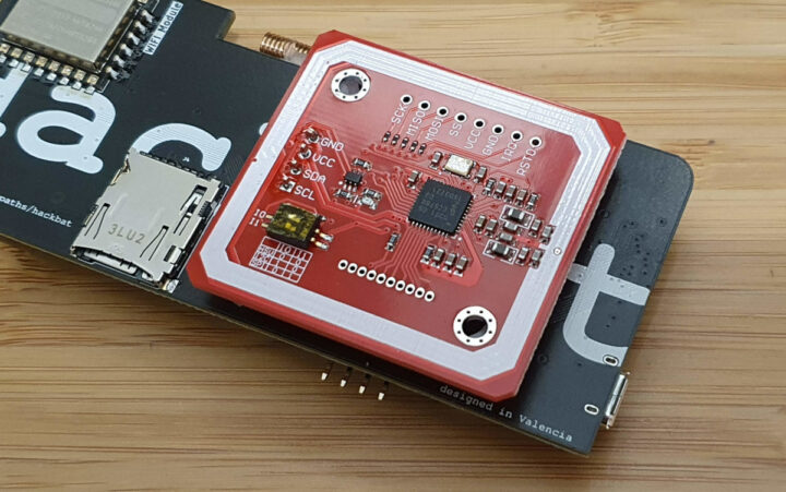
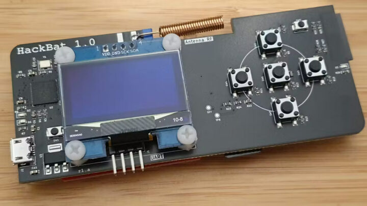
HackBat is an open-source hardware pen-testing device designed for hackers and makers and equipped with a Raspberry Pi RP2040 microcontroller, an ESP8266 WiFi module, a sub-GHz RF transceiver, NFC, an OLED display, and more… It’s basically a DIY alternative to the popular Flipper Zero wireless hacking tool, that you can produce and assemble yourself.
The Flipper Zero was the victim of its own success with the Canadian government (wrongly) claiming it could easily be used for car theft and planning to ban it (status still unclear right now), so Flipper Zero alternatives such as the M1 multitool device got some traction as backup solutions with some extra features. But any closed-source device could eventually be banned, something that’s close to impossible for an open-source hardware device like the HackBat although policymakers could still decide to impose heavy fines if they wanted to make this type of device illegal…
HackBat key features and specifications:
- Microcontroller – Raspberry Pi RP2040 dual-core Cortex-M0 processor at 133MHz and 264kB RAM.
- Storage
- 4MB (32Mbit) flash by default
- MicroSD card slot
- Display – 0.96-inch OLED with 128×64 resolution connected (SH110X driver); note: OLED with SSD1306 are also supported but the VCC and GND pins are reversed and two 0 Ohm resistors need to be soldered
- Wireless
- Texas instruments CC1101 sub-1 GHz transceiver with coil antenna (and optional SMA antenna connector) supporting 315, 433, 868, and 915 MHz bands as well as the 300-348 MHz, 387-464 MHz and 779-928 MHz bands
- ESP-12F ESP8266 module connected over UART to RP2040 and programmable through the RP2040 used as USB-UART bridge.
- NXP PN532 NFC module at 13.56MHz
- USB – 1x micro USB port for power, programming (RP2040 and ESP8266), and keyboard emulation
- User control – 5-key D-Pad
- Misc – 2x user LEDs, two extra system buttons
- Power Supply – 5V via micro USB port
- Dimensions – 100 x 42 mm

You’ll find the KiCad hardware design files including schematics, PCB layout, BoM, and Gerbers along with some documentation on GitHub, and as well as on Hackster.io. Since the HackBat is not for sale, you’d have to manufacture the PCB and do some soldering, or order the PCBA directly. If you’ve never done that, we reported our experience ordering PCBAs for another open-source hardware board using NextPCB a few years ago. It’s feasible, but you’ve never done that it will require some effort, even though the PCB design part is already done…
The other part of this DIY project would be the firmware, because Pablo Trujillo, the maker of the board, has yet to share any firmware, so unless things change, you’d also have to write your own RP2040 firmware to play with the HackBat. Luckily, it’s mostly based on off-the-shelf parts with available Arduino libraries which should somewhat simply the programming part.
Via ZDNET

Jean-Luc started CNX Software in 2010 as a part-time endeavor, before quitting his job as a software engineering manager, and starting to write daily news, and reviews full time later in 2011.
Support CNX Software! Donate via cryptocurrencies, become a Patron on Patreon, or purchase goods on Amazon or Aliexpress. We also use affiliate links in articles to earn commissions if you make a purchase after clicking on those links.


Weird combination, why not just drop the RP2040 and use a esp32?
Might be even more useful if used ESP32-C6 to also add IEEE 802.15.4 (Thread or Zigbee) and Bluetooth?
Probably need the dual cores for user interface + sampling to take place concurrently.
Hi, where are the code? I couldn’t see it on github
As mentioned in the article, there’s no source code, you have to write it yourself.
The hardware is open source.
😥