
Xiaomi Mi Box 3 Enhanced launched earlier this year, must be one of the most powerful Android TV Box thanks to its Mediatek MT8693 hexa-core processor with two ARM Cortex-A72 cores @ 2.0GHz and four Cortex-A53 cores @ 1.6 GHz coupled with Imagination PowerVR GX6250 GPU. The downside is that the product has been specifically launched for the Chinese market, however we can still purchase it via Chinese e-retailers, and likely modify the user interface to use English. To find out, GearBest sent me one review sample. But first, I’ll check the device and hardware, before fully reviewing the TV box in a few weeks.
Xiaomi Mi Box 3 Enhanced Unboxing
I normally received samples by DHL, but this time the postman brought it to me. It’s slower, but it can also be advantageous since custom duties are less likely.
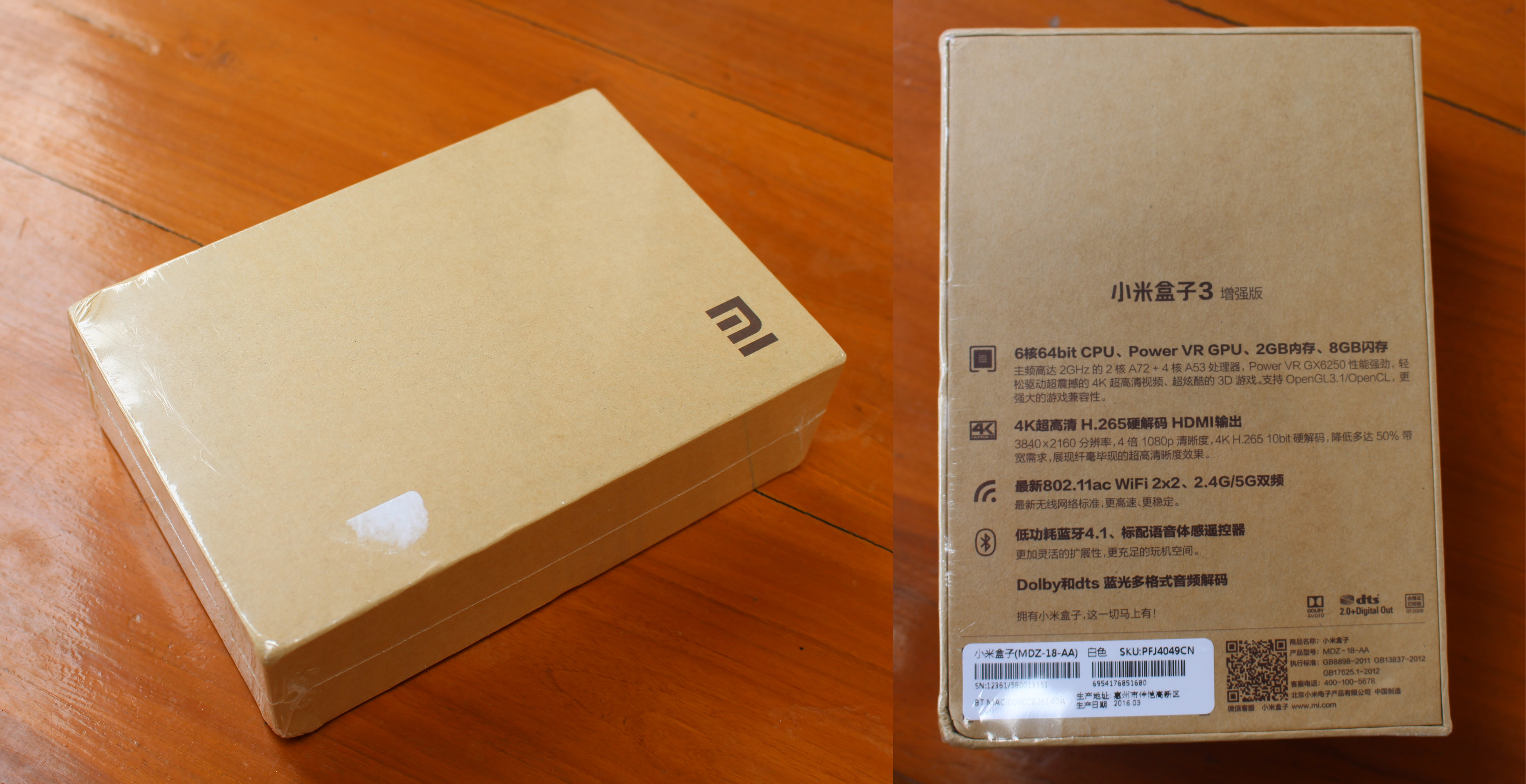
The package has not much to it, but the back makes it clear it’s made for China as the specs are all listed in Chinese.

The white TV box comes with a Bluetooth remote control with two AAA batteries and a strap, a 12V/1.2A power supply, an HDMI cable, and a user’s guide in Chinese only.
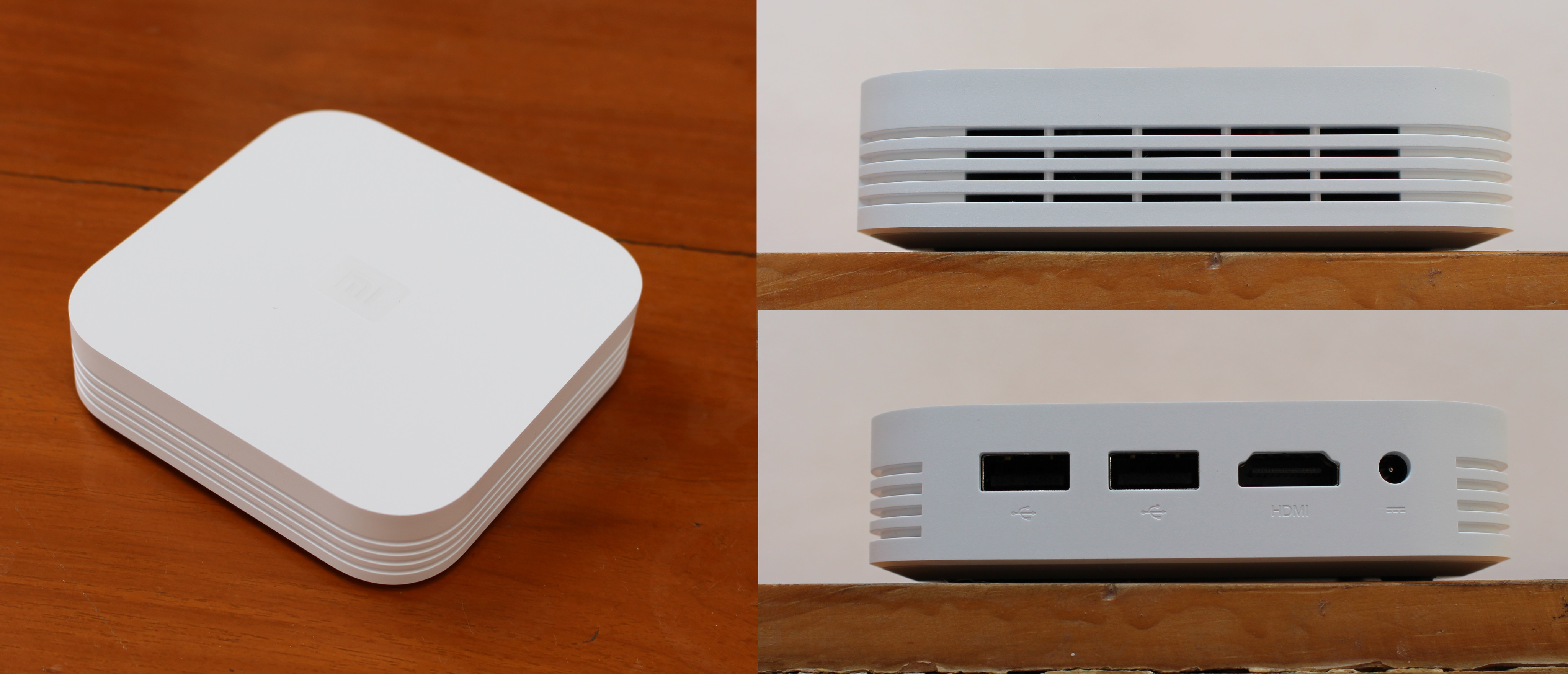
The device is rather small, with ventilation on the side, and only four port on the rear panel with two USB 2.0 ports, an HDMI 2.0 output port, and the DC jack. Xiaomi does not seem to think wired network matters much now, so they have not included an Ethernet port.
Xiaomi Mi Box 3 Enhanced Unboxing
The device is quite hard to open as the two parts are tightly fitted together. I had to use two metal tools, one above one of the USB port to create an opening on the bottom, and another to pop the bottom cover out using that opening.
Processor based on ARM Cortex A72 do get hot, and as per the marketing materials released by Xiaomi the device includes a large heatsink and a fan.
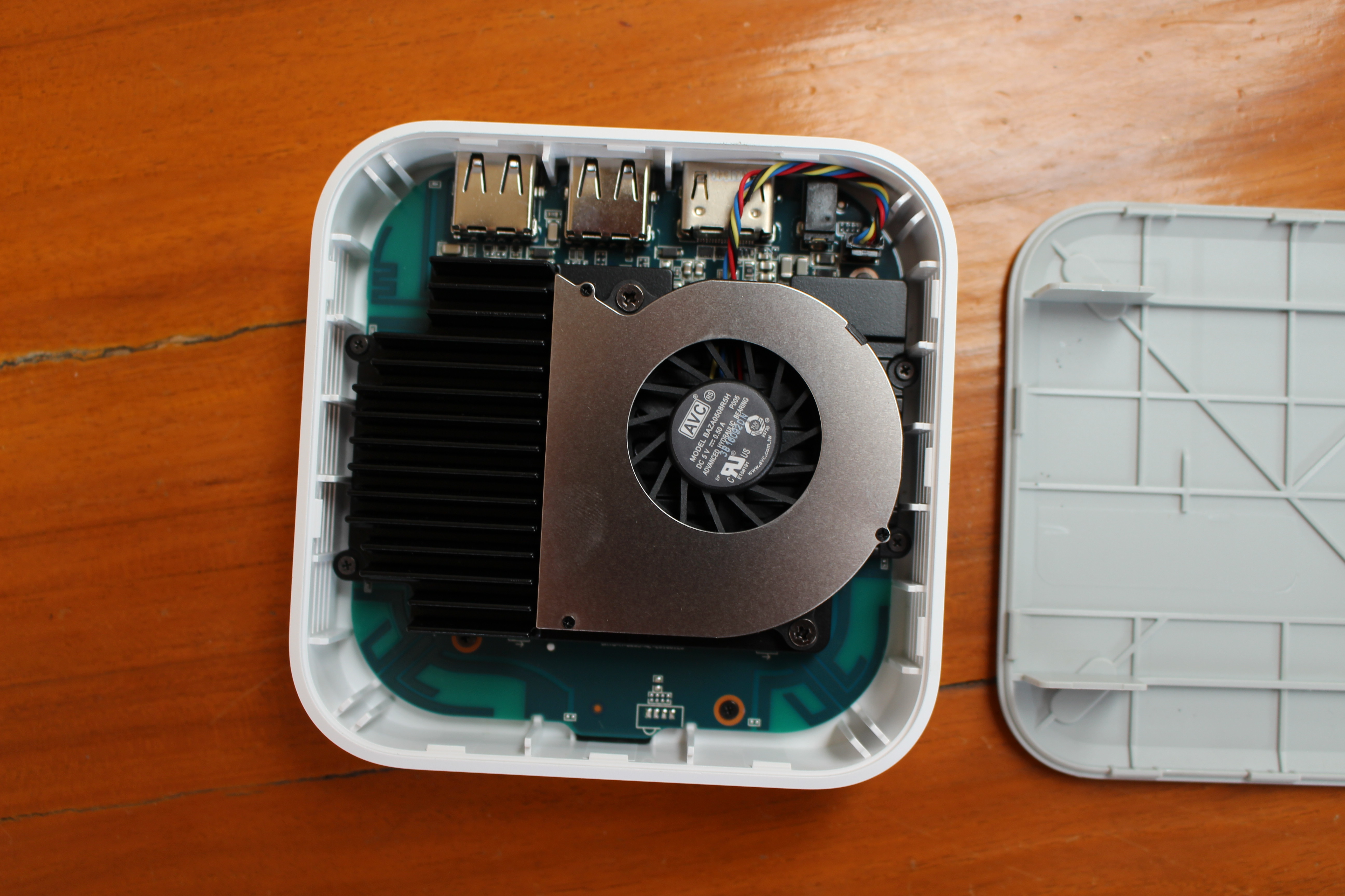
I could remove the fan after loosening two screws…
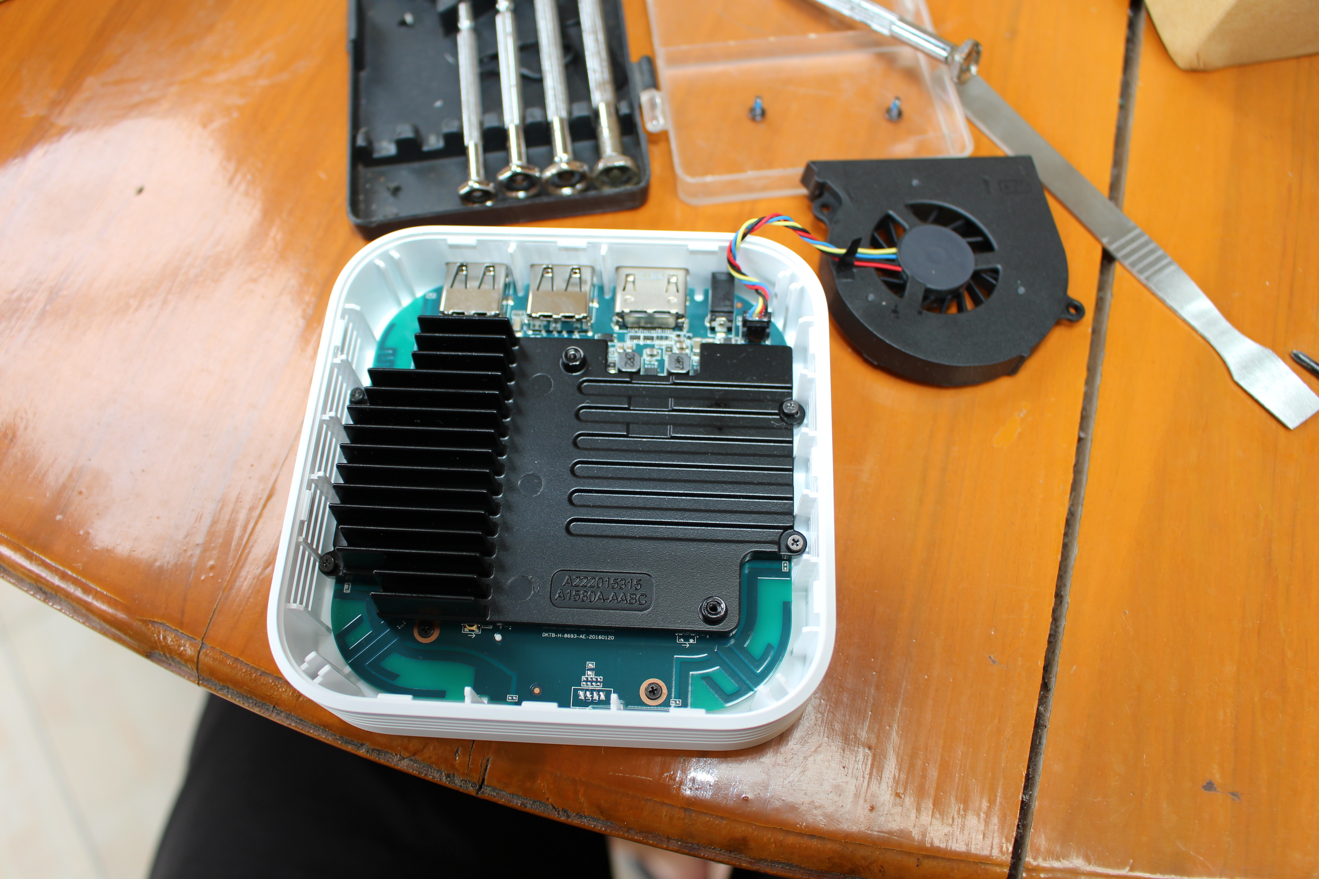
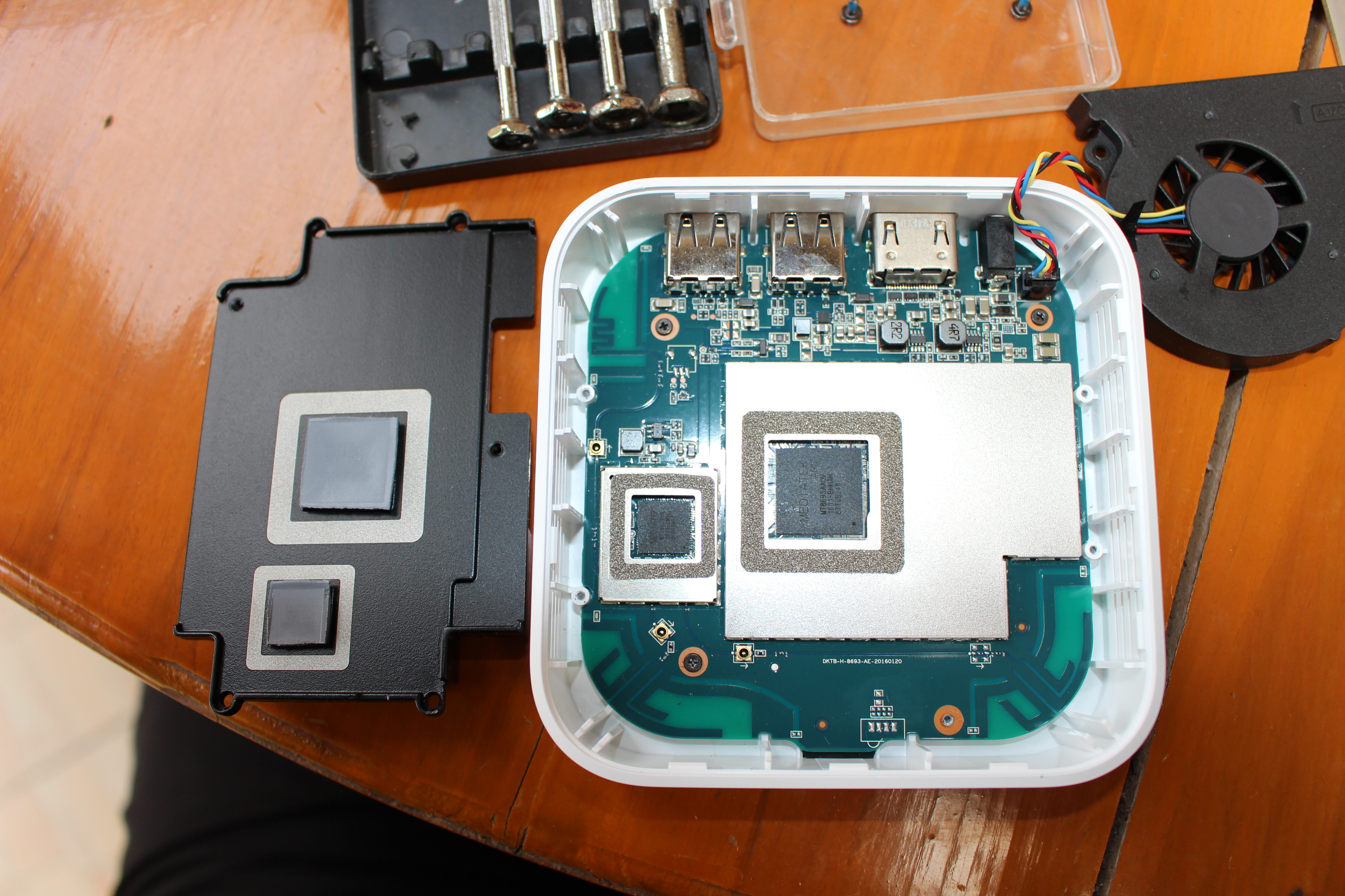
and finally take out the heatsink after removing a bunch of smaller screws. The thermal design seems to be pretty good with two thermal pads connected to the heatsink. and covering the two main ICs: Mediatek MT8693 AAOV hexa-core SoC, and Mediatek MT7662 TUN handling WiFi 802.11 n/g/n/ac and Bluetooth 4.0 connectivity.
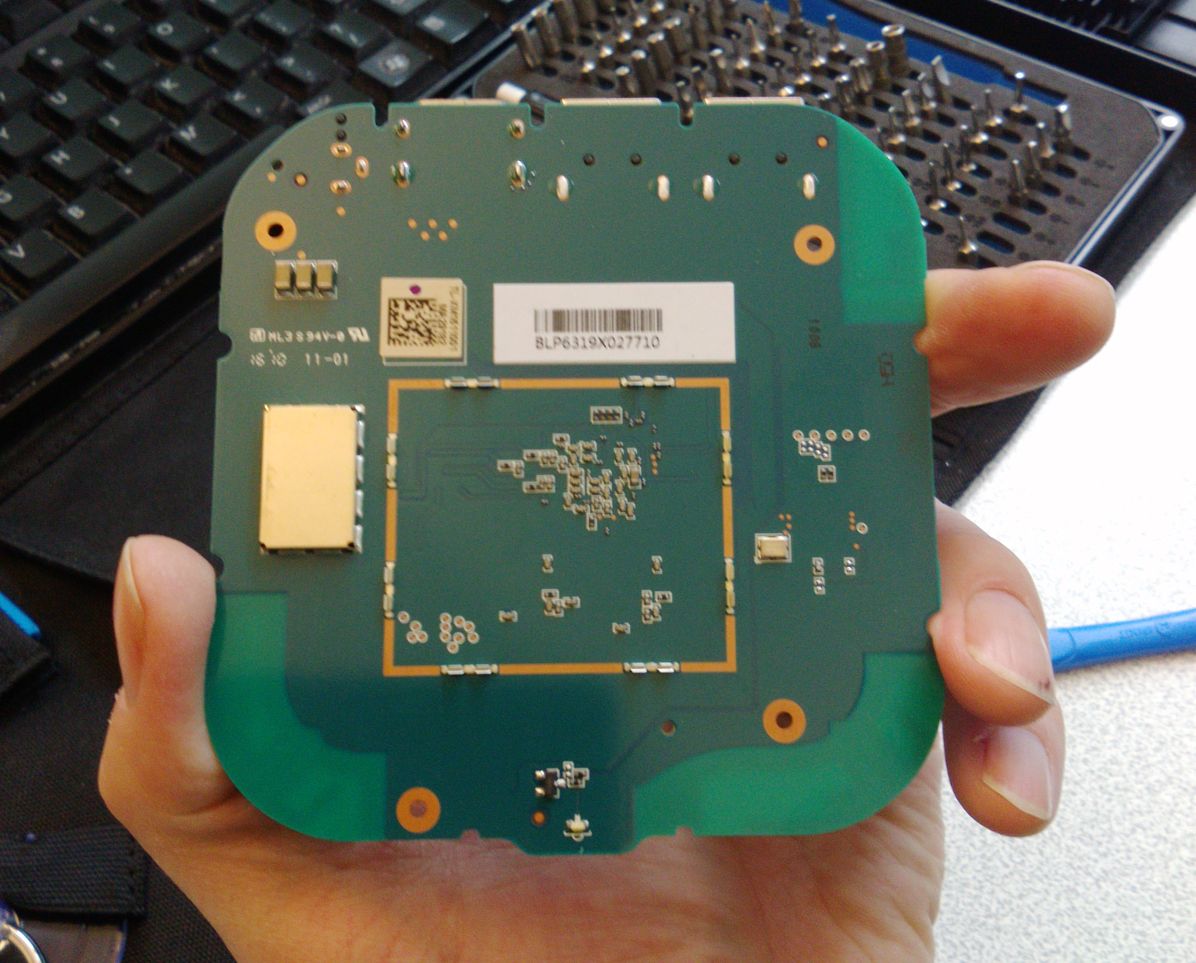
 The metal shield appears to be soldered, and one of the three small screws holding the board with the case could not be easily removed, so I did not disassemble it further. It’s also interesting to notice three small connectors, that look like antenna connectors, but are unused. The unpopulated 4-pin header at the bottom of the picture above
 could be for the serial console. (Sadly not: see comment below).
[Update: I got a few more pictures thanks to Andreas
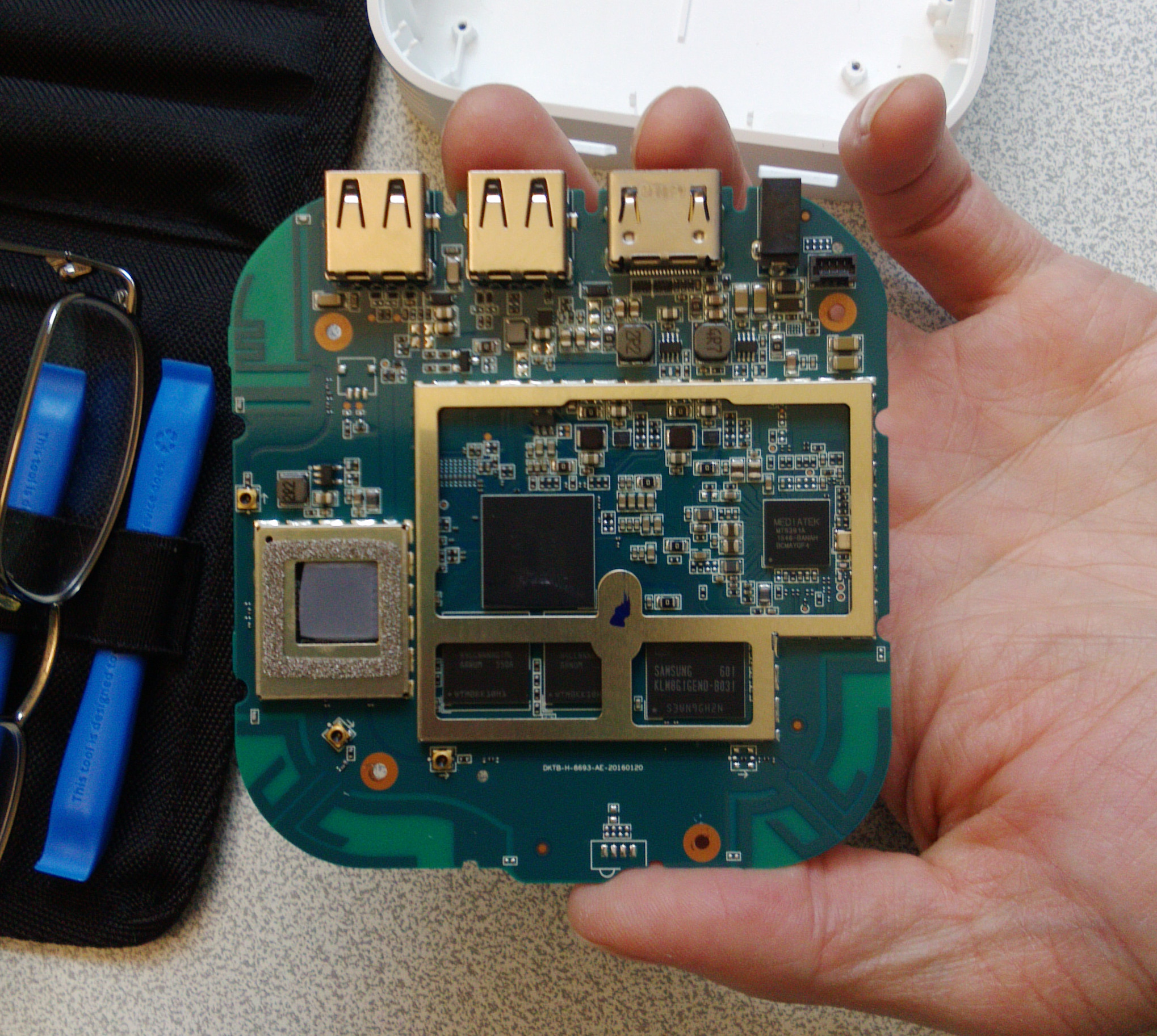
So we’ve got another Mediatek chip with MT6391A PMIC, Samsung KLM8G1GEND-B031 eMMC 5.0 flash (8GB) and two RAM chips]
I’d like to thank GearBest for sending the latest version of Xiaomi Mi Box 3 TV box for review, and you could consider purchasing the device on their website for $85.05 shipped. Alternative shopping options include GeekBuying under the name Xiaomi Mi Box 3 Pro, and Aliexpress.

Jean-Luc started CNX Software in 2010 as a part-time endeavor, before quitting his job as a software engineering manager, and starting to write daily news, and reviews full time later in 2011.
Support CNX Software! Donate via cryptocurrencies, become a Patron on Patreon, or purchase goods on Amazon or Aliexpress


Actually the shieldings were not soldered, just very tight. The one inner corner is probably the easiest place to start. Or I can share pictures from top and bottom around the SoC if you contact me; didn’t investigate the Wifi myself.
Unfortunately those four promising solder pads had GND left and right, and the pins in the middle did not look like RX/TX. In fact I checked some dozen test points and could not identify UART pins – if someone else has more success, please share!
@Andreas
Thanks for the pictures. Are you trying to run/port Linux on it?
The Wi-Fi “antenna” points are test points that are used during manufacturing and they’re different to the uFL connectors used for Wi-Fi antennas. This board is using “PCB” antennas, i.e. they’re integrated into the main PCB and there’s one in each of the three corners where you can sort of see through the board.
very nice box and very good heatsink with 4 pin fan (speed control).
One way I’ve found to check for UART is to just use the digital multimeter set continuous DC voltage. One point must be set to a GND and the other can be used to check while booting.
If it’s an UART it will show 1.5 V or 3.3 V when nothing is being sent from the board and about half ( I had about 1.7 – 1.8 V for a 3.3V UART ) that during boot-up when lots of messages are being sent on the UART.
@Jean-Luc Aufranc (CNXSoft)
Sure, I would love to investigate that…
That other chip is an MT6391A and I assumed it would be some PMIC. Coreboot code seems to confirm that: https://github.com/coreboot/coreboot/blob/master/src/soc/mediatek/mt8173/mt6391.c
@TLS
Thanks. I can see those three test points are also connected to the PCB antennas, so they might be to test the wireless signals.
@Andreas
Thanks for the correction. It’s also confirmed by others in China @ http://bbs.mydigit.cn/read.php?tid=1597333
There should be photos in that page too, but I think registration is required.
Could the serial interface be located under the WiFi shield?