Last year we discovered Kendryte K210 processor with a RISC-V core and featuring AI accelerators for machine vision and machine hearing. Soon after, Sipeed M1 module was launched with the processor for aroud $10.
Then this year we started to get more convenient development board featuring Sipeed M1 module such as Maixduino or Grove AI Hat. Seeed Studio sent me the last two boards for review. So I’ll start by showing the items I received, before showing how to get started with MicroPython and Arduino code. Note that I’ll be using Ubuntu 18.04, but development in Windows is also possible.
Unboxing
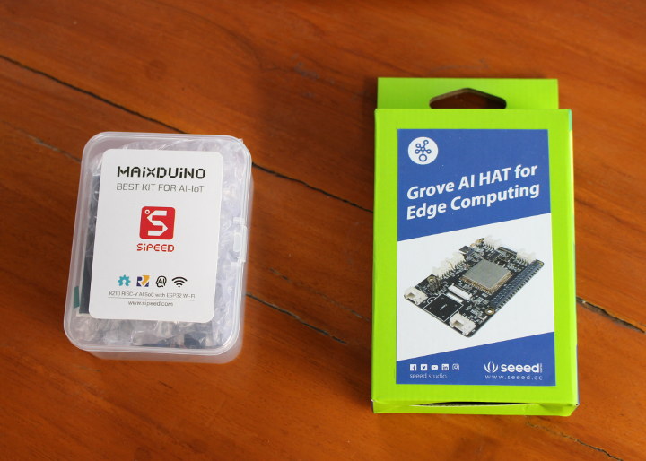
I received two packages with a Maixduino kit, and the other “Grove AI HAT for Edge Computing”.
Grove AI HAT for Edge Computing
Let’s start with the second. The board is a Raspberry Pi HAT with Sipeed M1 module, a 40-pin Raspberry Pi header, 6 grove connectors, as well as connectors for camera and display. The USB-C port is used for programming and power in standalone mode.
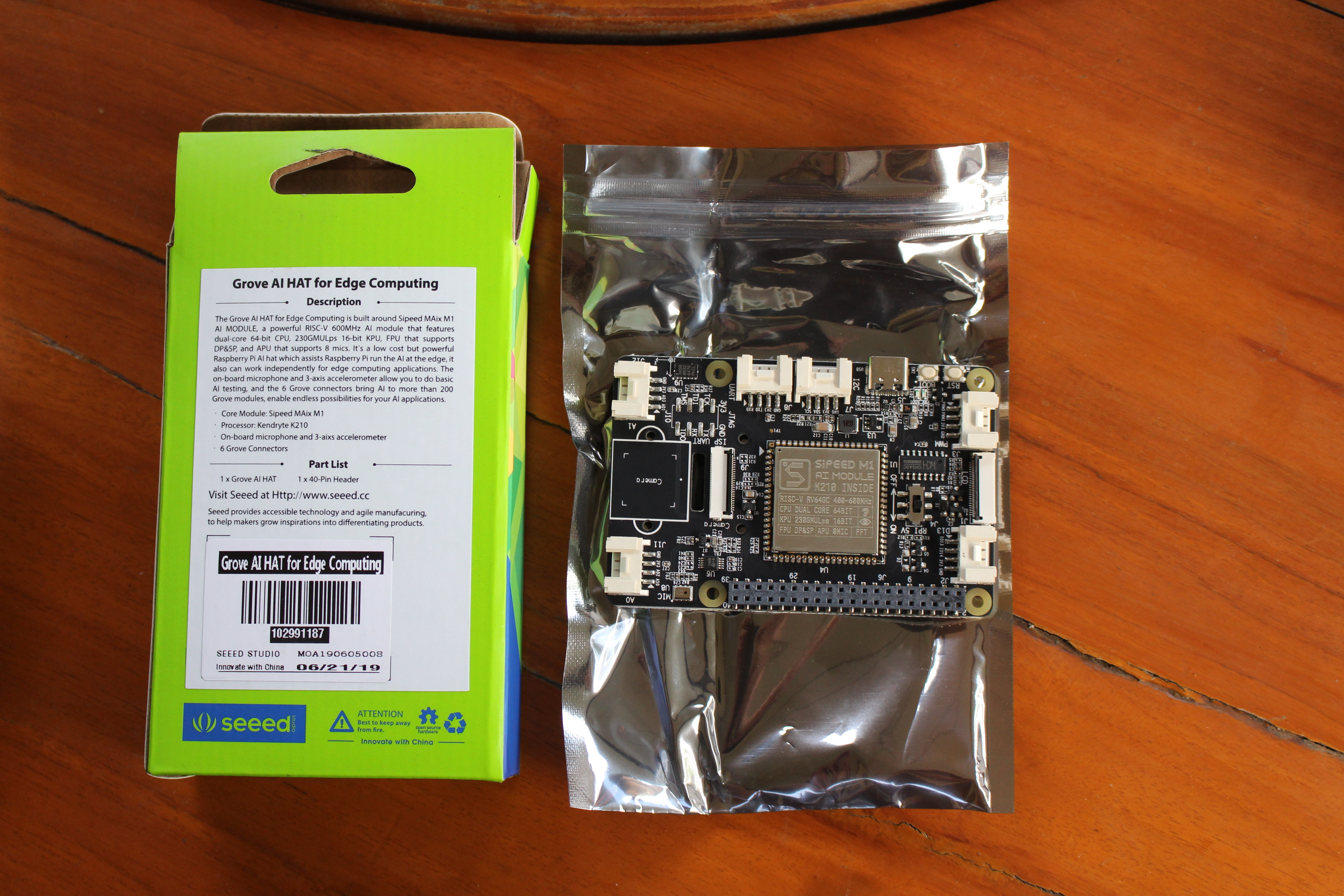
There are also headers for the board, but failed to see them during unboxing. We’ll see them when I insert them into the board.
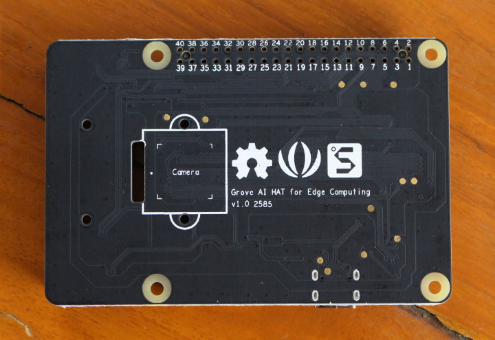 The bottom side does not have much expect numbering the I/O header pins, and another mount point for the camera.
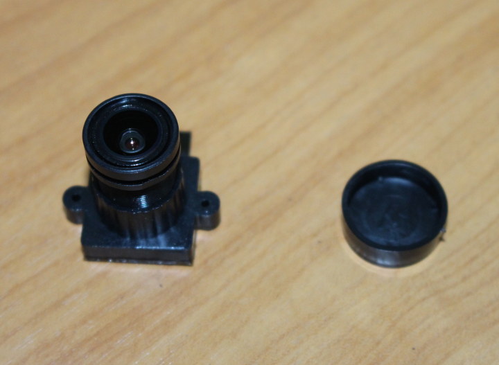
Later on I received the camera for the board as well.
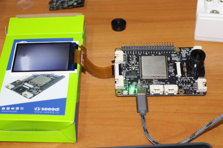
Maixduino kit
The second package includes a Maixduino Arduino compatible board with Sipeed M1 module and an ESP32 module. The camera is already attached to the board, and a 2.4″ color display (QVGA resolution) is also part of the package.
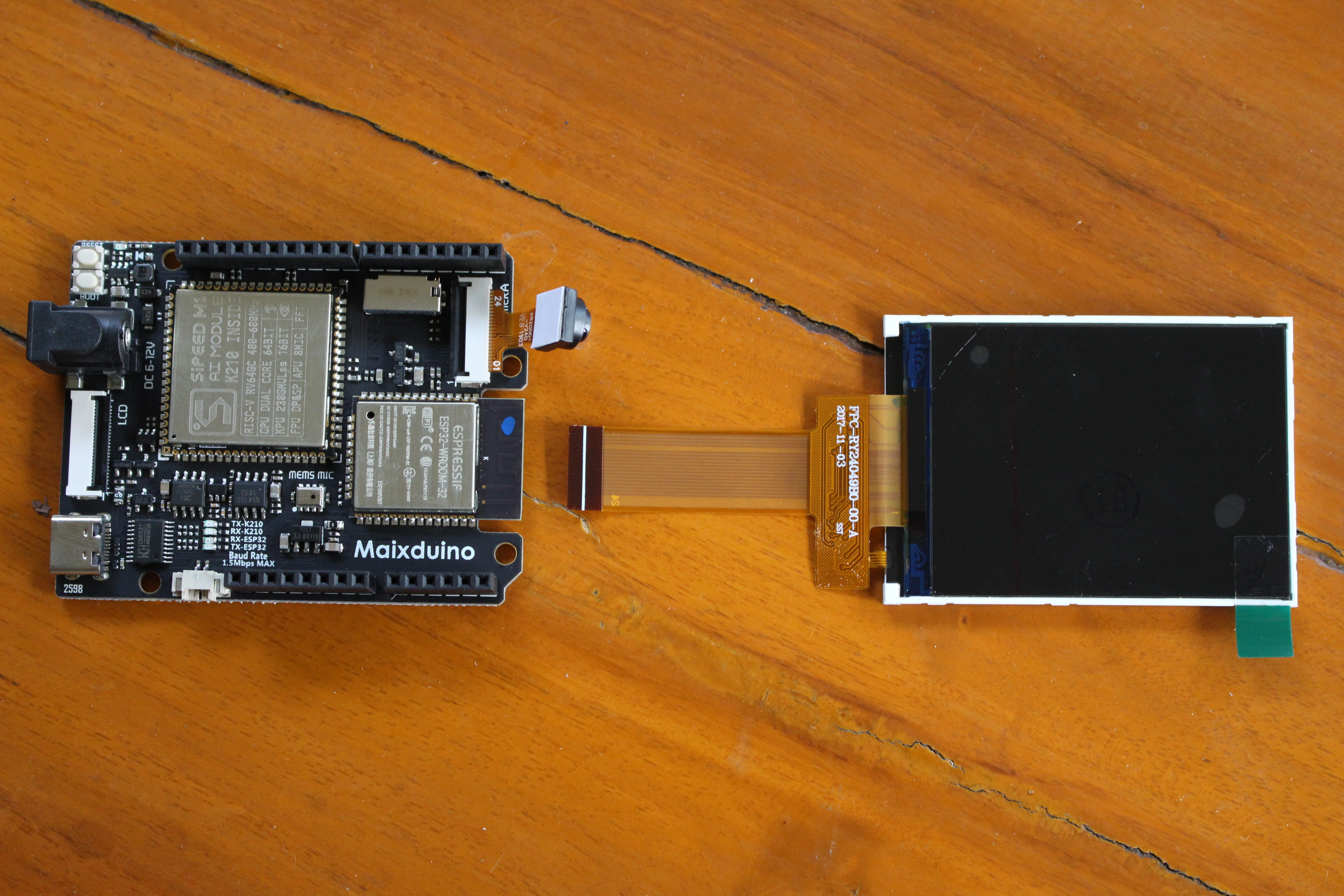
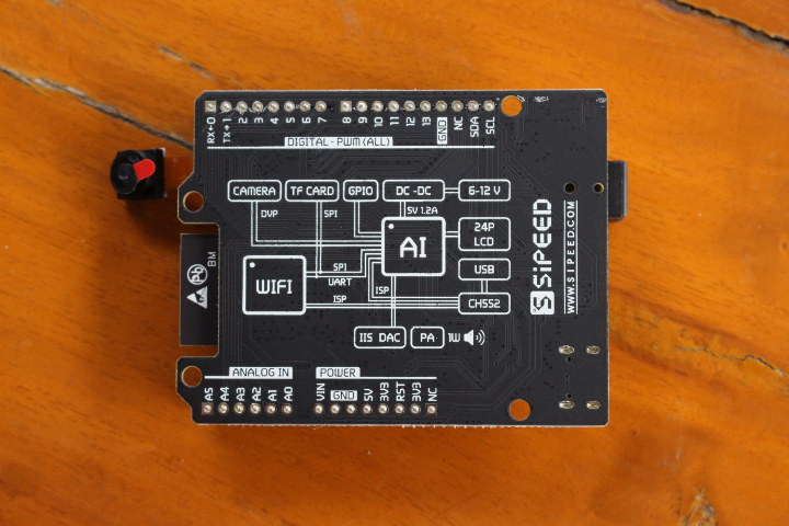
The bottom side of the board just include silkscreen for the header pin names, as well as a block diagram for the board.
Getting Started with Maixduino Kit using MicroPython
I’ll start with Maixduino first, trying to following some of the instructions from the Wiki, and other resources from the Internet since it’s somewhat incomplete or inaccurate at times.
There are 4 methods of development / SDKs:
- MaixPy (MicroPython)
- Maxduino (Arduino)
- Kendryte SDK, the official SDK of Kanji, providing the basic API
- RT_Thread – RT-Thread support
I’ll use the first one for the pupose of this tutorial / getting started guide.
But first let’s connect a USB type-C cable and see what happens.
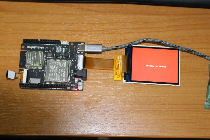
The board does start with “Welcome to MaixPy” written over a red background.
Firmware upgrade
Let’s upgrade the firmware as per the Wiki instructions. We could either build the firmware from source or get a binary.
I just went with the latest version available the first time I tried.
|
1 |
wget -r --no-parent http://dl.sipeed.com/MAIX/MaixPy/release/master/maixpy_v0.4.0_39_g083e0cc/ |
There are four files in the directory:
- elf_maixpy_v0.4.0_39_g083e0cc.7z – elf file, ordinary users do not care, used for crash debugging
- maixpy_v0.4.0_39_g083e0cc_m5stickv.bin – For M5Stack’s M5StickV AI camera
- maixpy_v0.4.0_39_g083e0cc_minimum.bin – MaixPy firmware minimum set, not supported by MaixPy IDE, does not contain OpenMV related algorithms
- maixpy_v0.4.0_39_g083e0cc.bin – Full version of MaixPy firmware (MicroPython + OpenMV API + LittlevGL embedded GUI framework)
I’ll use the later, but before going further let’s add ourselves to the dialout group and set some udev rules to be able to access /dev/ttyUSB? as a normal user:
|
1 |
sudo usermod -a -G dialout $(whoami) |
Create /etc/udev/rules.d/50-usbuart.rules file with the following line:
|
1 |
SUBSYSTEM=="tty", ATTRS{idVendor}=="0403", ATTRS{idProduct}=="6010", MODE="0666" |
Now download the latest kflash_gui program for your operating system (Linux or Windows). I got version 1.5.3, extract it and started it:
|
1 2 3 |
tar xvf kflash_gui_v1.5.3_linux.tar.xz cd kflash_gui ./kflash_gui |
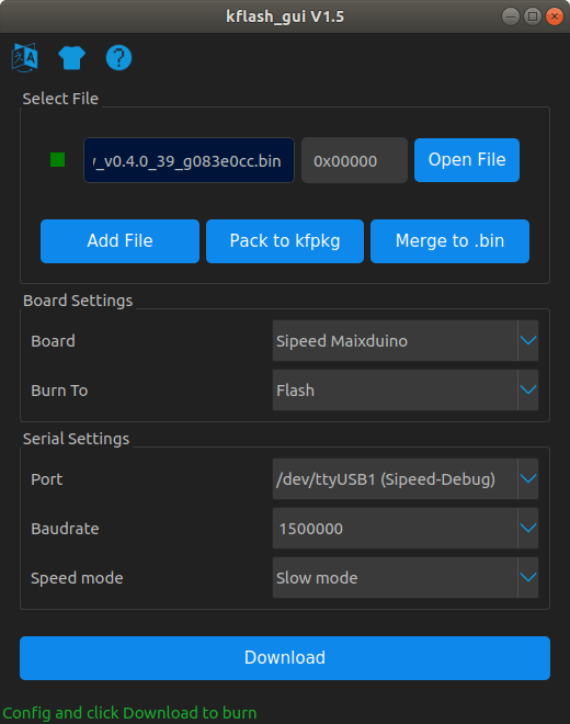
Now we can open the firmware file, select Sipeed Maixduino, as well as the serial port. To do so I looked into the kernel log (dmesg) to find out:
|
1 2 3 4 5 6 7 8 9 10 11 12 13 14 15 16 |
[ 8446.580336] usb 1-2.4: new full-speed USB device number 11 using xhci_hcd [ 8448.559536] usb 1-2.4: New USB device found, idVendor=0403, idProduct=6010, bcdDevice= 5.00 [ 8448.559540] usb 1-2.4: New USB device strings: Mfr=1, Product=2, SerialNumber=3 [ 8448.559542] usb 1-2.4: Product: Sipeed-Debug [ 8448.559545] usb 1-2.4: Manufacturer: Kongou Hikari [ 8448.559546] usb 1-2.4: SerialNumber: 414E10D04D [ 8449.173986] usbcore: registered new interface driver usbserial_generic [ 8449.174005] usbserial: USB Serial support registered for generic [ 8449.187366] usbcore: registered new interface driver ftdi_sio [ 8449.187376] usbserial: USB Serial support registered for FTDI USB Serial Device [ 8449.187447] ftdi_sio 1-2.4:1.0: FTDI USB Serial Device converter detected [ 8449.187473] usb 1-2.4: Detected FT2232C [ 8449.582711] usb 1-2.4: FTDI USB Serial Device converter now attached to ttyUSB0 [ 8449.582772] ftdi_sio 1-2.4:1.1: FTDI USB Serial Device converter detected [ 8449.582840] usb 1-2.4: Detected FT2232C [ 8450.094673] usb 1-2.4: FTDI USB Serial Device converter now attached to ttyUSB1 |
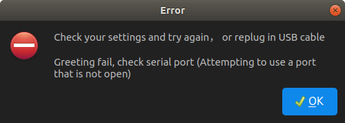
I looked a bit too fast only only noticed the last line with ttyUSB1, and I got some errors…
Also I tried with the command line Python utility, and same results:
|
1 2 3 4 5 6 |
jaufranc@CNX-LAPTOP-4:~/edev/Kendryte/kflash_gui/kflash_py$ ./kflash.py -b 1500000 -p /dev/ttyUSB1 -B goE ../../dl.sipeed.com/MAIX/MaixPy/release/master/maixpy_v0.4.0_39_g083e0cc/maixpy_v0.4.0_39_g083e0cc.bin [INFO] COM Port Selected Manually: /dev/ttyUSB1 [INFO] Default baudrate is 115200 , later it may be changed to the value you set. [INFO] Trying to Enter the ISP Mode... ** Greeting fail, check serial port (Attempting to use a port that is not open) |
I asked Seeed Studio, and I was told to use the other port, and it worked!
Looking at the kernel log above, I can actually see both ttyUSB0 and ttyUSB1 assigned to Maixduino, and with hindsight, that’s probably because we can access both ESP32 and Kendryte K210 processors over different serial ports through a single USB cable.
However when I connected to /dev/ttyUSB0 via minicom (115200 8N1), there seems to be an issue with the firmware:
|
1 2 3 4 5 6 7 8 9 10 11 12 13 14 |
[MAIXPY]Pll0:freq:832000000 [MAIXPY]Pll1:freq:398666666 [MAIXPY]Pll2:freq:45066666 [MAIXPY]cpu:freq:416000000 [MAIXPY]kpu:freq:398666666 [MAIXPY]Flash:0xc8:0x17 open second core... gc heap=0x801702e0-0x801f02e0 [MaixPy] init end Traceback (most recent call last): File "_boot.py", line 17, in <module> NameError: name 'time' isn't defined MicroPython v0.4.0-39-g083e0cc-dirty on 2019-08-13; Sipeed_M1 with kendryte-k210 Type "help()" for more information. |
MaixPy version 0.4.0 I’ve just used is a pre-release firmware, so I’ve switched to MaixPy 0.3.2 that’s considered an actual stable release. This time I use the command line tool:
|
1 2 3 4 5 6 7 8 9 10 11 12 13 14 15 16 17 18 19 20 21 22 |
sudo apt update sudo apt install python3 python3-pip sudo pip3 install pyserial sudo pip3 install pyelftools wget http://dl.sipeed.com/MAIX/MaixPy/release/master/maixpy_v0.3.2_x/maixpy_master_2019_07_19_04_42_40_9f3862f.bin ./kflash.py -b 1500000 -p /dev/ttyUSB0 -S 1 -B goE maixpy_master_2019_07_19_04_42_40_9f3862f.bin [INFO] COM Port Selected Manually: /dev/ttyUSB0 [INFO] Default baudrate is 115200 , later it may be changed to the value you set. [INFO] Trying to Enter the ISP Mode... * [INFO] Greeting Message Detected, Start Downloading ISP Downloading ISP: |=============================================| 100.0% 10kiB/s [INFO] Booting From 0x80000000 [INFO] Wait For 0.1 second for ISP to Boot [INFO] Boot to Flashmode Successfully [INFO] Selected Baudrate: 1500000 [INFO] Baudrate changed, greeting with ISP again ... [INFO] Boot to Flashmode Successfully [INFO] Selected Flash: On-Board [INFO] Initialization flash Successfully Programming BIN: |=============================================| 100.0% 52kiB/s [INFO] Rebooting... |
Let’s see the output from the serial console:
|
1 2 3 4 5 6 7 8 9 10 11 12 13 14 15 16 17 18 19 20 21 22 23 |
>>> [MAIXPY]Pll0:freq:832000000 [MAIXPY]Pll1:freq:398666666 [MAIXPY]Pll2:freq:45066666 [MAIXPY]cpu:freq:416000000 [MAIXPY]kpu:freq:398666666 [MAIXPY]Flash:0xc8:0x17 open second core... gc heap=0x8016d4e0-0x801ed4e0 [MaixPy] init end __ __ _____ __ __ _____ __ __ | \/ | /\ |_ _| \ \ / / | __ \ \ \ / / | \ / | / \ | | \ V / | |__) | \ \_/ / | |\/| | / /\ \ | | > < | ___/ \ / | | | | / ____ \ _| |_ / . \ | | | | |_| |_| /_/ \_\ |_____| /_/ \_\ |_| |_| Official Site : https://www.sipeed.com Wiki : https://maixpy.sipeed.com MicroPython 9f3862f on 2019-07-19; Sipeed_M1 with kendryte-k210 Type "help()" for more information. |
All good. Let’s try to get more information with help():
|
1 2 3 4 5 6 7 8 9 10 11 12 13 14 15 16 17 18 19 20 21 22 23 24 25 26 27 28 29 30 31 32 33 |
>>> help(); Welcome to MicroPython on the Sipeed Maix! For generic online docs please visit https://maixpy.sipeed.com Official website : http://www.sipeed.com Control commands: CTRL-A -- on a blank line, enter raw REPL mode CTRL-B -- on a blank line, enter normal REPL mode CTRL-C -- interrupt a running program CTRL-D -- on a blank line, do a soft reset of the board CTRL-E -- on a blank line, enter paste mode For further help on a specific object, type help(obj) For a list of available modules, type help('modules') >>> help('modules') KPU hashlib random uheapq Maix heapq re uio __main__ image sensor ujson _boot json socket uos _webrepl lcd struct urandom audio machine sys ure binascii math time usocket board math touchscreen ustruct builtins micropython ubinascii utime cmath modules ucollections utimeq collections nes ucryptolib uzlib errno network uctypes video fpioa_manager os uerrno zlib gc pye_mp uhashlib Plus any modules on the filesystem >>> |
This gives list of modules, and we can help(‘<module_name>’) to get a list of functions for each module. That’s not the most user-friendly way to learn, so let’s get back to the Wiki, and check the sample to capture a photo and show it on display:
|
1 2 3 4 5 6 7 8 9 10 11 12 |
import sensor import image import lcd lcd.init() sensor.reset() sensor.set_pixformat(sensor.RGB565) sensor.set_framesize(sensor.QVGA) sensor.run(1) while True: img=sensor.snapshot() lcd.display(img) |
Actual output in terminal:
|
1 2 3 4 5 6 7 8 9 10 11 12 13 14 15 16 |
>>> import sensor >>> import image >>> import lcd >>> lcd.init() >>> sensor.reset() init i2c2 [MAIXPY]: find ov2640 >>> sensor.set_pixformat(sensor.RGB565) True >>> sensor.set_framesize(sensor.QVGA) >>> sensor.run(1) True >>> while True: ... img=sensor.snapshot() ... lcd.display(img) ... |
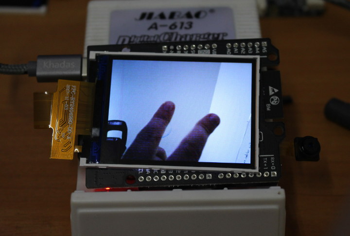
We can indeed see the camera output on the attached display.
As your program grows, the REPL interface where you type commands in the serial console becomes impractical. But good news the company also designed MaixPy IDE to more conveniently write and load code to the board.
I wanted to use the latest MaixPy IDE 0.2.4 which required firmware 0.4.0 or greater. I had no luck with 0.4.0.39 I could see a new release had just been build on August 16th, so I flashed it:
|
1 2 3 4 5 6 7 8 9 10 11 12 13 14 15 16 17 |
./kflash.py -b 1500000 -p /dev/ttyUSB0 -B goE -S 1 maixpy_v0.4.0_44_g95f00f0.bin [INFO] COM Port Selected Manually: /dev/ttyUSB0 [INFO] Default baudrate is 115200 , later it may be changed to the value you set. [INFO] Trying to Enter the ISP Mode... * [INFO] Greeting Message Detected, Start Downloading ISP Downloading ISP: |=============================================| 100.0% 10kiB/s [INFO] Booting From 0x80000000 [INFO] Wait For 0.1 second for ISP to Boot [INFO] Boot to Flashmode Successfully [INFO] Selected Baudrate: 1500000 [INFO] Baudrate changed, greeting with ISP again ... [INFO] Boot to Flashmode Successfully [INFO] Selected Flash: On-Board [INFO] Initialization flash Successfully Programming BIN: |=============================================| 100.0% 52kiB/s [INFO] Rebooting... |
This time, the board could boot. Good. Time to install and launch MaixPy IDE in Ubuntu 18.04:
|
1 2 3 4 5 6 |
mkdir MaixPy-IDE cd MaixPy-IDE wget http://dl.sipeed.com/MAIX/MaixPy/ide/_/v0.2.4/maixpy-ide-linux-x86_64-0.2.4-installer-archive.7z 7z x maixpy-ide-linux-x86_64-0.2.4-installer-archive.7z ./setup.sh ./bin/maixpyide.sh |
The last line launches the IDE with the default hello world program.
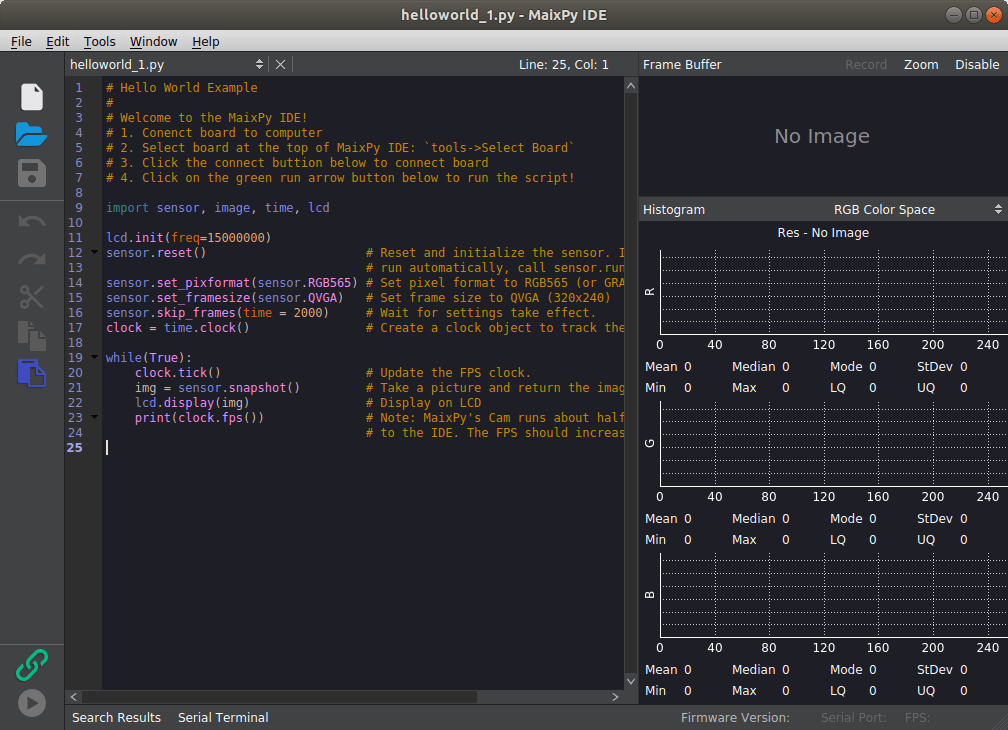
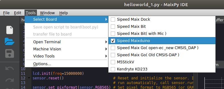
We should now select Maixduino in Tools->Select Board:
Click on the green chain link icon on the bottom left of the ID and select /dev/ttyUSB0 to connect to the board, and once it’s done press the “Play” button underneath to load and run the Hello World sample on Maixduino.
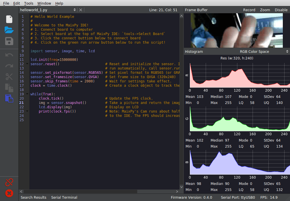
The top right zone shows the actual frame buffer, and the three zones underneath the R, G & B histograms.
It’s all good but the highlight of K210 processor is its KPU AI / machine vision accelerator. There’s documentation to help us.
First let’s download the models:
|
1 |
wget -r --no-parent http://dl.sipeed.com/MAIX/MaixPy/model/ |
There are three:
|
1 2 3 |
ls face_model_at_0x300000.kfpkg mobilenet_0x300000.kfpkg mobilenet_7_5_224_tf.h5 |
“Face model” is a pre-trained tiny Yolo-v2 model to detect (human) faces, and the other two are mobilenet. I’ll run the Yolo-V2 demo.

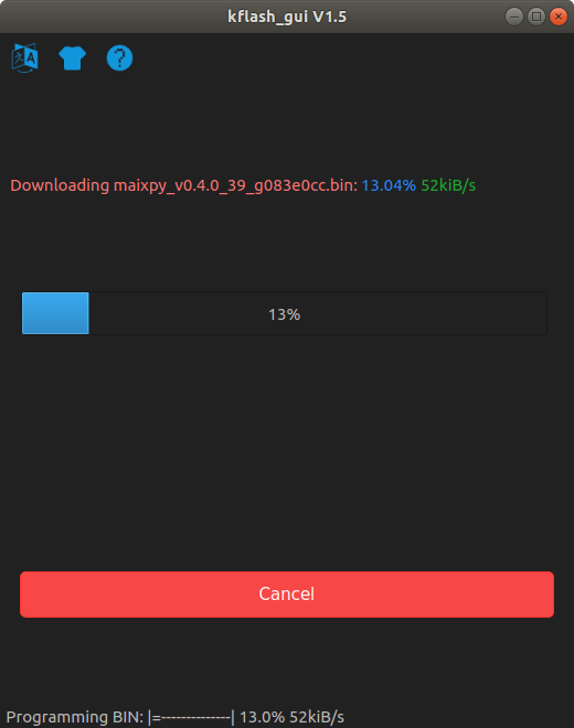
We can get back to kflash_gui, load the model, and click Download to flash it to the board.
Now we can write (copy/paste) Yolo2 code in the IDE:
|
1 2 3 4 5 6 7 8 9 10 11 12 13 14 15 16 17 18 19 20 21 22 |
import sensor import image import lcd import KPU as kpu lcd.init() sensor.reset() sensor.set_pixformat(sensor.RGB565) sensor.set_framesize(sensor.QVGA) sensor.run(1) task = kpu.load(0x300000) anchor = (1.889, 2.5245, 2.9465, 3.94056, 3.99987, 5.3658, 5.155437, 6.92275, 6.718375, 9.01025) a = kpu.init_yolo2(task, 0.5, 0.3, 5, anchor) while(True): img = sensor.snapshot() code = kpu.run_yolo2(task, img) if code: for i in code: print(i) a = img.draw_rectangle(i.rect()) a = lcd.display(img) a = kpu.deinit(task) |
First part until sensor.run(1) is to setup the camera, as we’ve done in the previous example, and the KPU part is initialized with three lines:
|
1 2 3 |
task = kpu.load(0x300000) anchor = (1.889, 2.5245, 2.9465, 3.94056, 3.99987, 5.3658, 5.155437, 6.92275, 6.718375, 9.01025) a = kpu.init_yolo2(task, 0.5, 0.3, 5, anchor) |
The first line loads the model we’ve just flashed at address 0x300000. The second line defines the anchors for Yolo V2. Those are predefined width & heights for Yolo “boxes”. More details about what Yolo anchors mean can be found on Github. The third line initializes Yolo on the KPU with five parameters:
kpu_net: kpu network objectthreshold: probability thresholdnms_value: box_iou thresholdanchor_num: number of anchorsanchor: anchor parameters previously defined
The while loop is pretty much self-explanatory: capture image, run yolo, if a face is detected draw a rectangle, push the result to the display, and loop again.
But does it actually work?
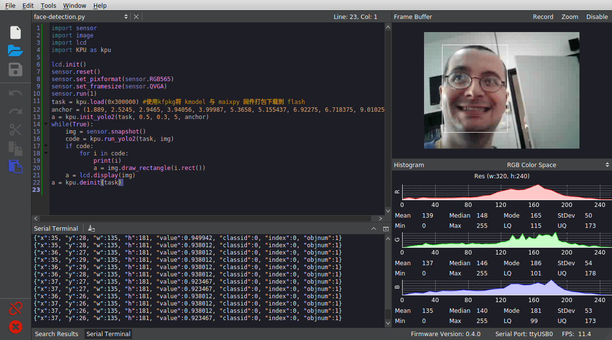
Yes, it does. Note recognition is done at around 11 fps in the IDE, but it will be faster when running standalone. So I’ve added code I found in Tiziano Fiorenzani’s MaixPy Dock demo to show the fps in the top left of the display:
|
1 2 3 4 5 6 7 8 9 10 11 12 13 14 15 16 17 18 19 20 21 22 23 24 |
import KPU as kpu lcd.init() sensor.reset() sensor.set_pixformat(sensor.RGB565) sensor.set_framesize(sensor.QVGA) sensor.run(1) task = kpu.load(0x300000) #使用kfpkg将 kmodel 与 maixpy 固件打包下载到 flash anchor = (1.889, 2.5245, 2.9465, 3.94056, 3.99987, 5.3658, 5.155437, 6.92275, 6.718375, 9.01025) a = kpu.init_yolo2(task, 0.5, 0.3, 5, anchor) clock = time.clock() while(True): clock.tick() img = sensor.snapshot() code = kpu.run_yolo2(task, img) if code: fps = clock.fps() img.draw_string(2,2, ("%2.1ffps" % (fps)), color=(0,128,0), scale = 4) for i in code: print(i) a = img.draw_rectangle(i.rect()) a = lcd.display(img) print (clock.fps()) a = kpu.deinit(task) |
I’ve then called an associate to help testing multiple faces detection, and shot a video.
Face detection/tracking is done at around 15 to 18 fps, and my panda friend did not get detected, but it’s probably more of a feature than a bug since the model must have been trained with human faces. When I tried before the panda could get tracked from time to time, but not quite as well as my face.
To go further you may want to use ESP32 features like WiFi and/or Bluetooth connectivity, but sadly there’s no documentation for it. I tried my ESP32 Micropython tutorial to setup WiFi but it did not work:
|
1 2 3 4 5 |
>>> import network >>> sta_if = network.WLAN(network.STA_IF); sta_if.active(True) Traceback (most recent call last): File "<stdin>", line 1, in <module> AttributeError: 'module' object has no attribute 'WLAN' |
I guess that’s normal since I’m running this in K210 instead of ESP32. I was hoping they may have adapted it. Looking at the help there are only a few function implemented:
|
1 2 3 4 5 6 |
>>> help(network) object <module 'network'> is of type module __name__ -- network ESP8285 -- <class 'ESP8285'> ESP32_SPI -- <class 'ESP32_SPI'> route -- <function> |
It’s not possible to use /dev/ttyUSB1 to connect to ESP32, so it may require a bit more work..
If you want to train and run your own models on Maixduino using Keras, a forum post provides the guideline to do just that.
Getting Started with Grove AI HAT
Standalone mode
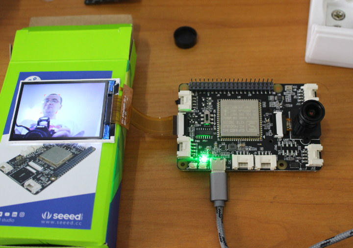
Let’s switch to the other board: Grove AI HAT which works both in standalone mode or connected to a Raspberry Pi. I’ll mostly follow the Wiki that shows how to use the board in standalone mode with the Arduino IDE, skipping the GPIO / Grove stuff, and jumping directly to the camera, display, and computer vision section.
I’ve connected the fisheye camera, inserted the pin headers, and borrowed the display from Maixduino kit. Note that you could also use Maixduino camera with Grove AI HAT, and I’ve tried but noticed face detection and tracking did not work as well.
I’ll assume you have already installed the Arduino IDE in your host computer. For reference, I’m using Arduino 1.8.9 in Ubuntu 18.04.
First we need to go to File->Preferences, and edit the “Additional Boards Manager URLs” with the following URL to add support for Seeed Studio boards:
|
1 |
https://raw.githubusercontent.com/Seeed-Studio/Seeed_Platform/master/package_seeeduino_boards_index.json |
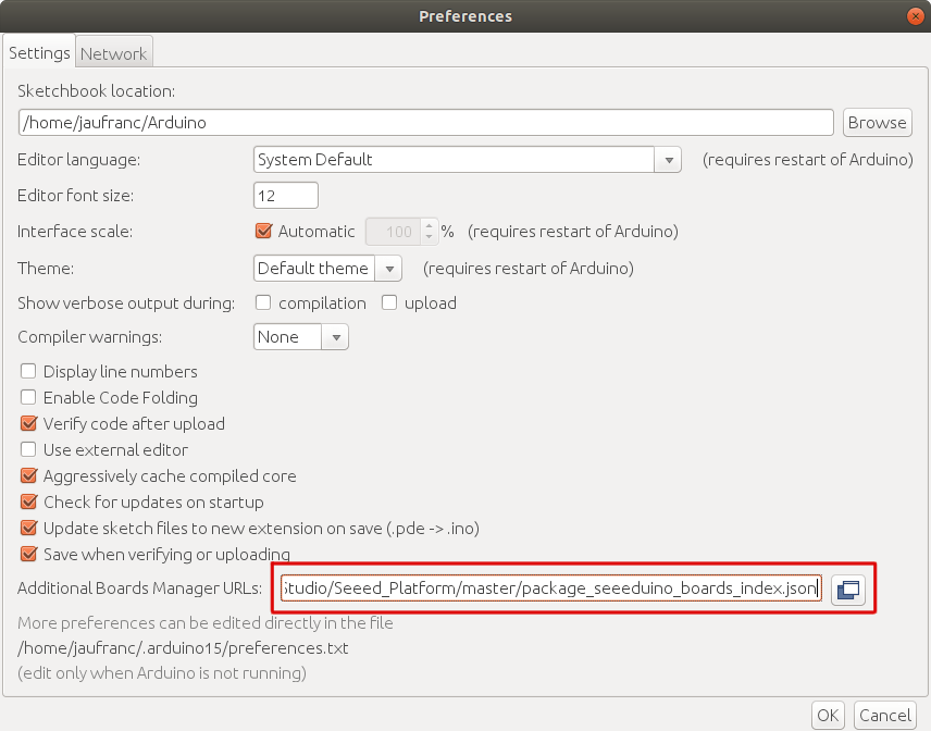
Please also note the path about “More preferences can be edited directly in the file” since we’ll see to access this directory later one.
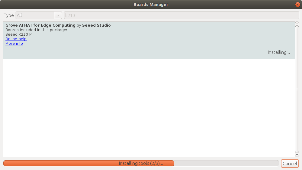
Now go to Tools->Board->Boards Manager and search for “k210”. Click Install when you see “Grove AI HAT for Edge Computing by Seeed Studio”.
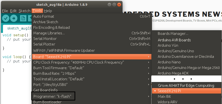
After a little while you should be good, and can select Seeed K210 Pi, and make sure “k-flash” programmer and /dev/ttyUSB0 are selected as illustrated below.
Now install Kendryte standalone SDK in your working directory:
|
1 |
git clone https://github.com/kendryte/kendryte-standalone-demo |
The model file needs to be manually flashed to the board (that’s where we use the path in Preferences as mentioned above):
|
1 2 |
cd kendryte-standalone-demo/face_detect/kfpkg $HOME/.arduino15/packages/Seeeduino/tools/kflash/1.3.0/kflash.py -n -p /dev/ttyUSB0 -b 2000000 -B dan face_detect.kfpkg |
Here’s the output of the last command if everything goes according to plans:
|
1 2 3 4 5 6 7 8 9 10 11 12 13 14 15 16 17 18 19 20 21 22 |
[INFO] ANSI colors not used [INFO] COM Port Selected Manually: /dev/ttyUSB0 [INFO] Default baudrate is 115200 , later it may be changed to the value you set. [INFO] Trying to Enter the ISP Mode... . [INFO] Greeting Message Detected, Start Downloading ISP [INFO] CH340 mode Downloading ISP: |=============================================| 100.0% 10kiB/s [INFO] Booting From 0x80000000 [INFO] Wait For 0.1 second for ISP to Boot [INFO] Boot to Flashmode Successfully [INFO] Selected Baudrate: 2000000 [INFO] Baudrate changed, greeting with ISP again ... [INFO] Boot to Flashmode Successfully [INFO] Selected Flash: On-Board [INFO] Initialization flash Successfully [INFO] Extracting KFPKG ... [INFO] Writing face_detect.bin into 0x00000000 Programming BIN: |=============================================| 100.0% 65kiB/s [INFO] Writing detect.kmodel into 0x00a00000 Programming BIN: |=============================================| 100.0% 79kiB/s [INFO] Rebooting... |
Now go back to your working directory and create a folder and empty sketch with the same name, in our case “face_detect”:
|
1 2 3 |
mkdir face_detect cd face_detect/ touch face_detect.ino |
Copy the content of face_detect from the SDK:
|
1 |
cp ../kendryte-standalone-demo/face_detect/* -rf . |
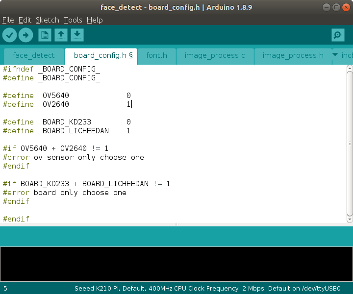
Now open face_detect.ino in Arduino IDE. This will open a bunch of other files automatically, including board_config.h which we need to modify to enable OV2640 sensor and LICHEEDAN board as illustrated below.
You can go to main.c to study the code, but it will require a bit more efforts to understand the code than Maixduino’s MicroPython sample. If you’d just like to try it out, you can check whether it compiles. I had a few warnings due to unused variables:
|
1 2 3 4 5 6 7 8 9 10 11 12 13 14 15 16 17 18 19 20 21 |
sketch/ov5640.c: In function 'ov5640_init': sketch/ov5640.c:266:14: warning: unused variable 'reg' [-Wunused-variable] uint16_t reg = 0; ^~~ At top level: sketch/ov5640.c:258:16: warning: 'ov5640_rd_reg' defined but not used [-Wunused-function] static uint8_t ov5640_rd_reg(uint16_t reg) ^~~~~~~~~~~~~ sketch/ov5640.c:248:13: warning: 'hal_delay' defined but not used [-Wunused-function] static void hal_delay(uint32_t delay) ^~~~~~~~~ sketch/region_layer.c: In function 'do_nms_sort': sketch/region_layer.c:312:56: warning: passing argument 4 of 'qsort' from incompatible pointer type [-Wincompatible-pointer-types] qsort(s, boxes_number, sizeof(sortable_box_t), nms_comparator); ^~~~~~~~~~~~~~ In file included from sketch/region_layer.c:1: /home/jaufranc/.arduino15/packages/Seeeduino/tools/riscv64-unknown-elf-gcc/8.2.0/riscv64-unknown-elf/include/stdlib.h:140:72: note: expected '__compar_fn_t' {aka 'int (*)(const void *, const void *)'} but argument is of type 'int (*)(void *, void *)' void qsort (void *__base, size_t __nmemb, size_t __size, __compar_fn_t _compar); ~~~~~~~~~~~~~~^~~~~~~ sketch/region_layer.c: In function 'region_layer_output': sketch/region_layer.c:351:14: warning: unused variable 'boxes_number' [-Wunused-variable] |
But it compiled fine:
|
1 |
Sketch uses 511916 bytes (6%) of program storage space. Maximum is 8388608 bytes. |
We can now upload the sketch right from the IDE:
|
1 2 3 4 5 6 7 8 9 10 11 12 13 14 15 16 17 18 19 20 21 22 23 24 25 26 27 |
[INFO] ANSI colors not used [INFO] COM Port Selected Manually: /dev/ttyUSB0 [INFO] Default baudrate is 115200 , later it may be changed to the value you set. [INFO] Trying to Enter the ISP Mode... . [INFO] Greeting Message Detected, Start Downloading ISP [INFO] CH340 mode Downloading ISP: |===----------------------------------------------------------------------------------------------------------------------------------------------------------------------------------------------------------| 1.5% ... Downloading ISP: |=========================================================================================================================================================================================================----| 98.5% 10kiB/s Downloading ISP: |=============================================================================================================================================================================================================| 100.0% 10kiB/s [INFO] Booting From 0x80000000 [INFO] Wait For 0.1 second for ISP to Boot [INFO] Boot to Flashmode Successfully [INFO] Selected Baudrate: 2000000 [INFO] Baudrate changed, greeting with ISP again ... [INFO] Boot to Flashmode Successfully [INFO] Selected Flash: On-Board [INFO] Initialization flash Successfully Programming BIN: |======================================================================================================-------------------------------------------------------------------------------------------------------| 50.0% Programming BIN: |=============================================================================================================================================================================================================| 100.0% 67kiB/s [INFO] Rebooting... |
The board will now capture video and show a red rectangle when a human face is detected in a similar fashion to the Maixduino MicroPyhon demo.
The display was up-side-down though. A small change to the code fixed that (see line 5 below):
|
1 2 3 4 5 6 7 8 |
#if BOARD_LICHEEDAN #if OV5640 lcd_set_direction(DIR_YX_RLUD); #else lcd_set_direction(DIR_YX_LRUD); /* lcd_set_direction(DIR_YX_RLDU);*/ #endif #else |
That’s basically like Maixduino demo above but instead of relying on MicroPython, we did so in the Arduino IDE.
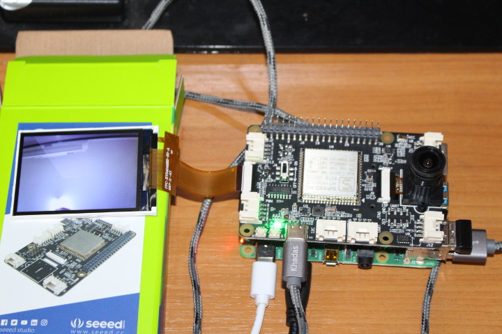
Grove AI HAT and Raspberry Pi 4
Since we have a HAT board that would be a shame if we did not also use it with a Raspberry Pi board. So I inserted the board into a Raspberry Pi 4 SBC, after disconnecting the power supply obviously. Talking about power, please make sure RPI 5V jumper on the top of the Grove AI HAT board is set to ON.
One of the first things I thought would be interesting was to develop code directly on the Raspberry Pi 4. So I installed Arduino 1.8.9 for Arm 32-bit, and loaded Seeed Studio board URL based on the instructions above.
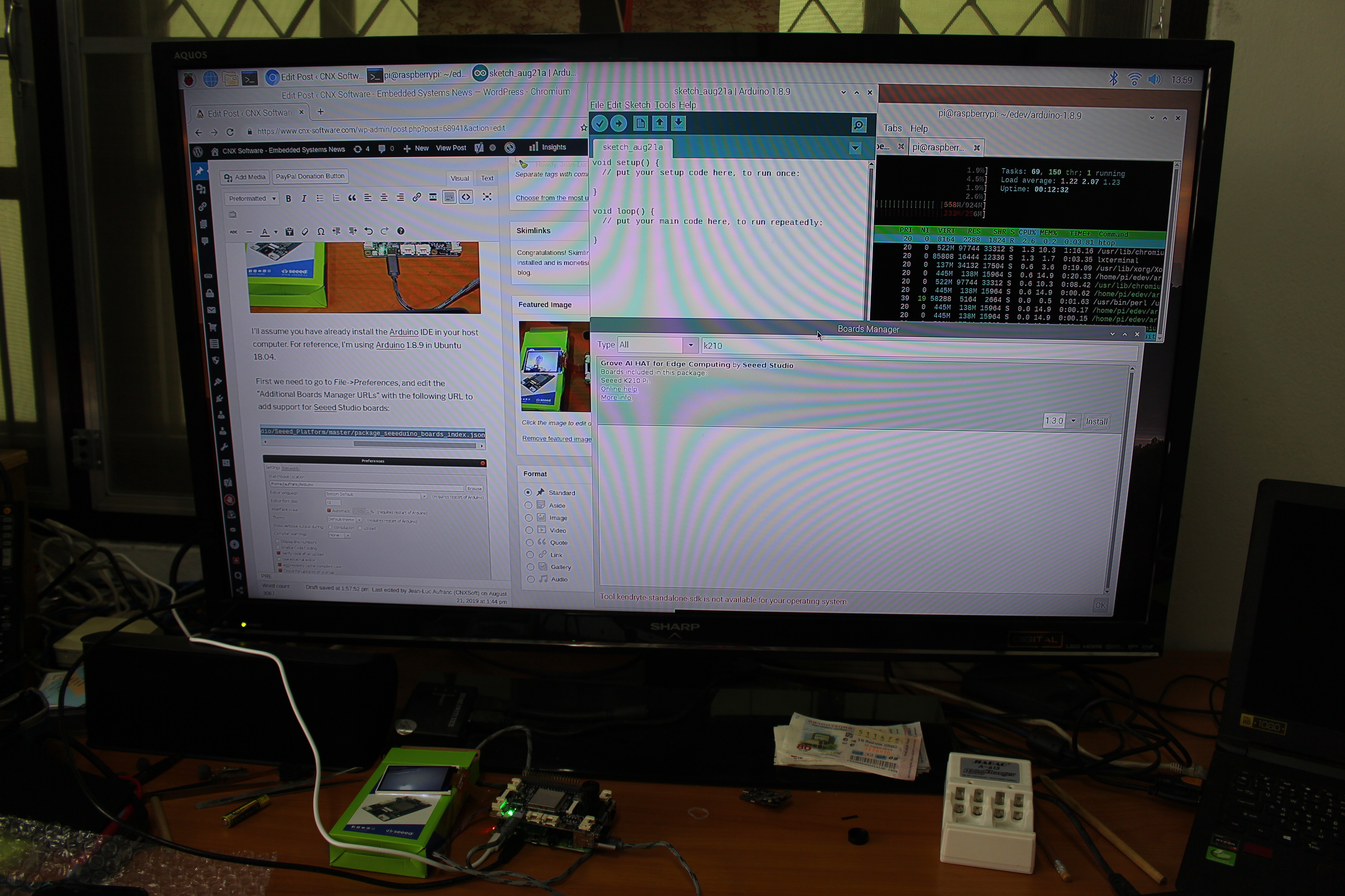
But when I tried to install “Grove AI HAT for Edge Computing by Seeed Studio” I quickly encountered a roadblock:
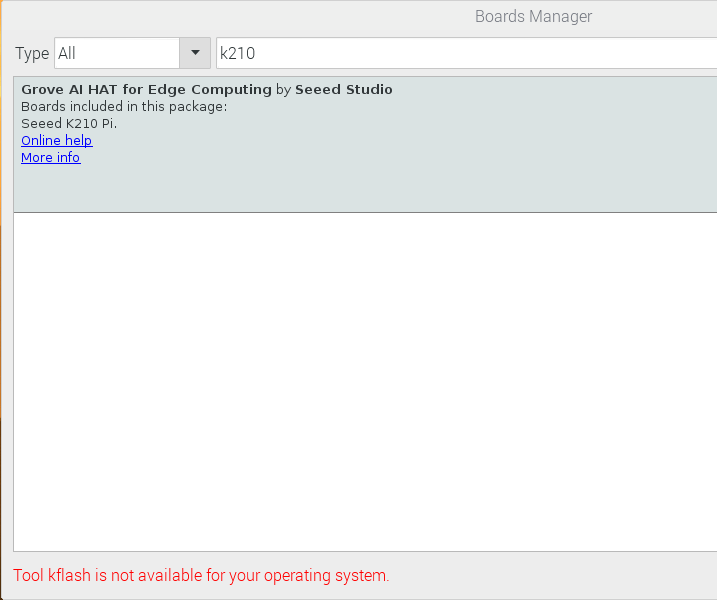
As a side note, I’m using Raspberry Pi 4 with 1GB, and I quickly found out it was not a good idea to run Chromium, even with just one tab, and the Android IDE side-by-side, as you quickly run out of memory, and it even completely filled the 512MB swap on the microSD card. Even with ZRAM there’s no hope, so if you ever considered running the Arduino IDE on Raspberry Pi 4 (e.g. for Arduino boards) while also checking out documentation, do yourself a favor and get the 2GB or 4GB RAM version.
Nevertheless, another way to use Grove AI HAT with Raspberry Pi is to display data returned by the expansion, as Seeed Studio explains in their face count demo tutorial. Let’s try it.
We’re off to a good start since we already setup the Arduino IDE above, and installed the face demo firmware. Now we can just install the Face Count program on the Raspberry Pi:
|
1 2 3 4 5 6 |
cd ~ git clone https://github.com/LynnL4/face-detected.git cd face-detected sudo chmod -R 777 installer cd installer sudo ./setup.sh |
However, if I run it a segfault occurs:
|
1 2 |
sudo ./face-detected.sh Segmentation fault |
Let’s have a look at setup.sh:
|
1 2 3 4 5 6 7 8 9 10 11 12 13 14 |
#!/bin/bash #start pi spi pwds=/boot/config.txt sudo sed -i 's/dtparam=spi=off//g' $pwds sudo sed -i 's/dtparam=spi=on//g' $pwds sudo sed -i '$a dtparam=spi=on' $pwds #reboot后生效 CurDir=$PWD"/face-detected.desktop" ExecDir=$PWD"/face-detected.sh" IconDir=$PWD"/Pyte_Data/icon.png" sudo sed -i "4c Exec=$ExecDir" $CurDir sudo sed -i "5c Icon=$IconDir" $CurDir sudo cp $CurDir /usr/share/applications/face-detected.desktop cp $CurDir /home/pi/Desktop/face-detected.desktop |
We can see the Grove AI HAT communicate with the Raspberry Pi board over SPI, and they set it by modifying /boot/config.txt file. So I decided to reboot, but the problem is the same. The installer directory contains many binary libraries which were tested on Raspberry Pi 3 B+ with Debian Wheezy, so switching to Raspberry Pi 4 with Debian Buster probably screwed things. I’ve let Seeed Studio know about it and they are looking into it.
Let’s complete the review by showing a video of the face detection demo running on Grove AI HAT, again joined by a few “friends”.
It works roughly as expected with the demo filtering out most of my non-human friends, and catching up to 3-4 faces simultaneously from a photo.
Purchasing the Boards, Display and Cameras
I’d like to thanks Seeed Studio for sending the board and let me experiment with Kendryte K210 / Sipeeed M1 platforms using MicroPython and Arduino. If you’d like to reproduce my setup, you can buy the Grove AI Hat for $28.90, the OV2640 fisheye camera for $7.60, and/or the Maixduino kit with the board, a display and a camera for $23.90.

Jean-Luc started CNX Software in 2010 as a part-time endeavor, before quitting his job as a software engineering manager, and starting to write daily news, and reviews full time later in 2011.
Support CNX Software! Donate via cryptocurrencies, become a Patron on Patreon, or purchase goods on Amazon or Aliexpress