A couple of weeks ago, I received IkaScope WS200 pen-like WiFi oscilloscope, as well as ScanaQuad SQ50 USB logic analyzer & signal generator, and I’ve already checked out the hardware both both in a aforelinked unboxing post. I had also very shortly tried IkaScope with GOLE 10 mini PC, but just to showcase potential use case for a Windows 10 mini PC with an inclined touchscreen display. But at the time I did not really a proper measurement, as it was more to test the mini PC than the oscilloscope itself.
I’ve now had time to test IkaScope desktop program and mobile app in respectively Ubuntu 16.04 and Android 8.0.0, as well as ScanaStudio for ScanaQuad USB device using Ubuntu 16.04 only, since there’s no mobile version of the program. While I’ll focus on Ubuntu and Android, most of the instructions will be valid for Window 10 and Mac OS X for the desktop programs, and iOS for the mobile app. This will be more of a getting started guide / basic tutorial, than a review, as I’ll go through some of the issues I may have come across, and show the basic functions of the program/app.
IkaScope with Android and Initial Setup
My original plan was to test the oscilloscope with my computer running Ubuntu 16.04, and then switch to Android. However, my computer is connected to the network via Ethernet, and I don’t have a spare working WiFi dongle anymore. The oscilloscope can also work with Ethernet only devices, as long as WiFi is configured in station mode, but by default it starts in access point mode, so I had to change my plan and instead install IkaScope Android app on my smartphone first.
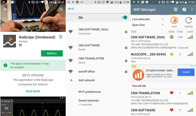
The app is still shown to be in development / a beta version, but as I did not encounter any critical issues, except at the beginning. To turn on the oscilloscope you have to press the probe tip, and should soon see the white LED blink, meaning some “IkaScopexxxx” access point should be setup and ready to go. However, after several attempts, I failed to find any IKASCOPE ESSID in the list of access point. Based on some recommendations on the Internet, I installed WiFiManager, and lo-and-behold IKDASCOPE-…200-00493 SSID showed up. I could easily connect to it, and since it’s an open network, no password is needed.
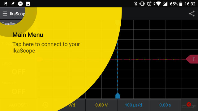
Time to launch IkaScope app. First you’ll go through a very short wizard showing the key zones in the app, and then we can tap on the top left corner, and click on Connect. It should then show your IkaScope in AP mode (White). 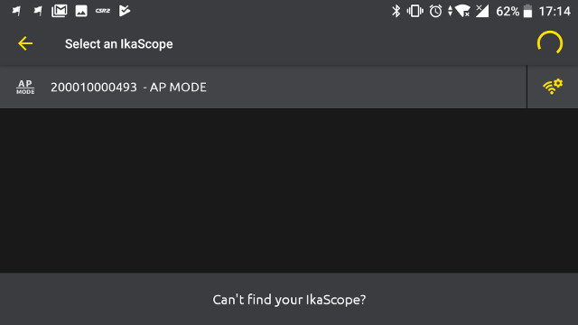
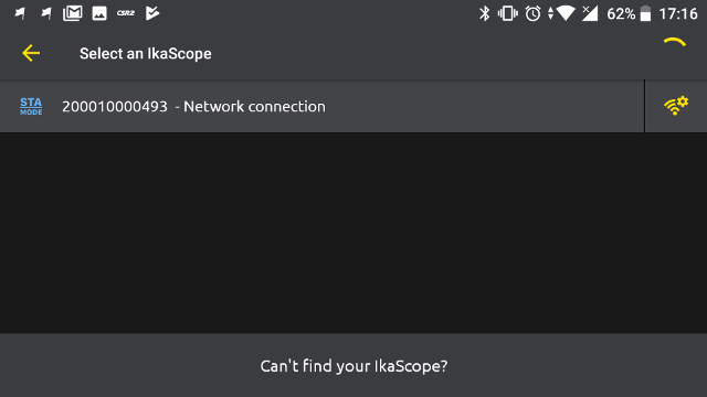
While you could just select it, and start measurements like when I did when I played with in in Windows 10, it is recommends to switch to station mode. To do so, tap on the setup/configuration on the right side, which should bring you to the “add a network” page as shown below.
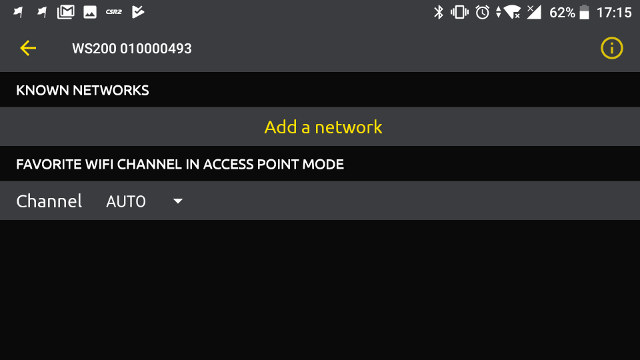 You can add just one, but if you add more, you’ll likely get better coverage. Note that the oscilloscope on supports 2.4 GHz, so your 5 GHz ESSID won’t show up.
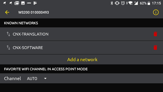
Now you can go back, maybe wait for the oscilloscope to turn off, and turn it on again by pressing the tip, and a solid Blue LED should show on the device…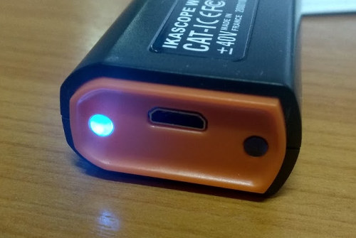
.. STA mode (Blue) icon will have replaced the AP mode (white) icon in the mobile app.
Go back again, and you’ll see IKASCOPE WS200 connected in station mode. The screenshot below also shows “CNX-SOFTWARE_5GHz” ESSID, but that’s the connection used by the phone, not the scope.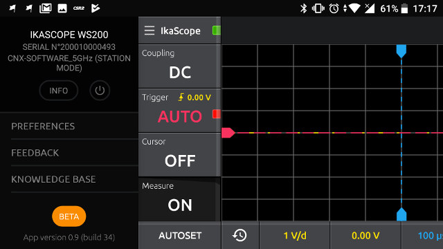
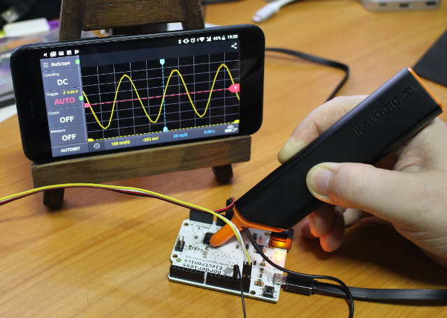
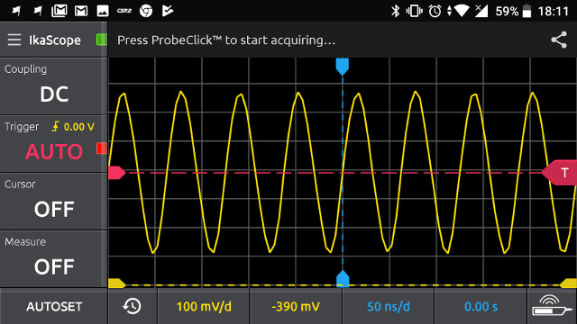
I’ll detailed the options about the app into more details in the Ubuntu section as they have the same features, and I could only find some cosmetic differences between the mobile and desktop version. I still used the Android app to measure the 16 MHz clock signal from an Arduino Leonardo clone as shown in the top picture.
You can see a short demo about the measurement below.
IkaScope in Ubuntu 16.04
Now that IkaScope WS200 probe is in station mode, I can use it with my Ethernet connected Ubuntu 16.04 computer.
You’ll find IkaScope desktop program on the company website for Windows (.exe) , Linux, and Mac OS X. In the case of Linux, the program is distributed as a tarball, which you need to extract, before running the installation script:
|
1 2 3 4 |
wget https://cdn.ikalogic.com/dist/ikascope/packages/IkaScope_x86_64.tar.bz2 tar xvf IkaScope_x86_64.tar.bz2 cd IkaScope/ sudo ./install.sh |
There’s also a an uninstall.sh script to remove the program if you don’t need it anymore. Note the tools only work on 64-bit x86 platforms (x86-64).
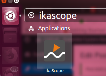 After installation IkaScope can be found in the dash, but if I click on the icon, nothing happens, even after a reboot. So I launched it from the terminal instead:
|
1 2 |
cd ~/Ikalogic/IkaScope/ ./IkaScope |
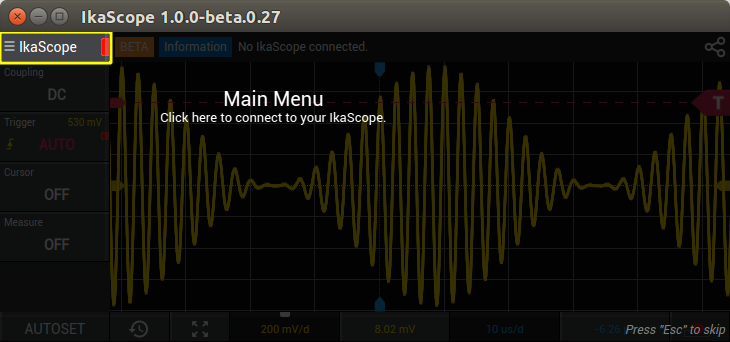
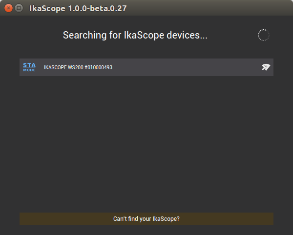
Just like in Android, you’ll get through a short “tutorial” at the beginning showing the main parts of the interface. Click on IkaScope icon on the top left corner of the program, and connect to find IkaScope.
My probe was already setup in Station mode, so all I had to do was to select, but if you are using a computer with WiFi, and WS200 probe is in AP mode, you’ll need to connect to the access point, and ideally change that to station mode as shown in the Android section.
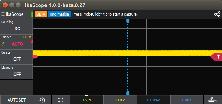
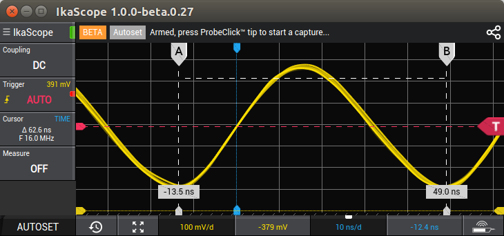
I did the same measurement on Arduino Leonardo board, but without using AUTOSET at first. You could then change the voltage and time resolution and offset as needed, but in most case, you’ll probably want to simply use AUTOSET to let the program automatically select the best settings.
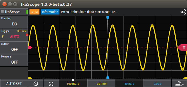
A 16 MHz signal has a 62.5 ns period, so first I used the cursor in TIME mode, and moved A and B to confirm both the period and frequency.
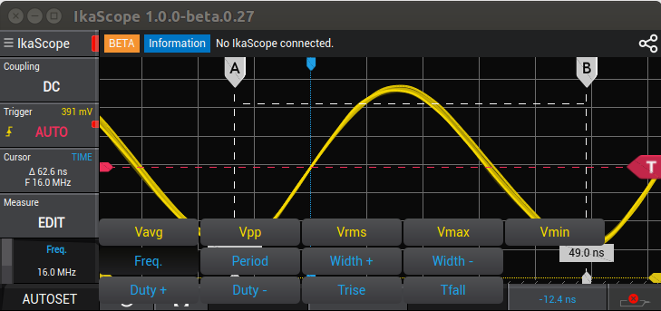
Cursors can also be used for voltage (vertical scale). An easier to check the frequency is to use the Measure menu, which allows to automatically reports frequency, period, width, duty, voltage average/peak-to-peak/rms/max/min, and rising and falling times.
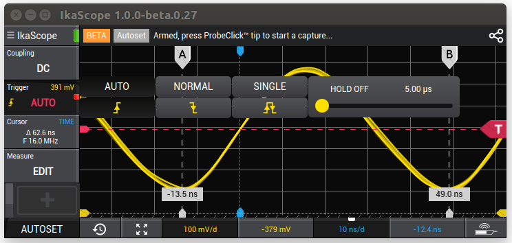
Other options include coupling (DC or AC), and Trigger which can be set to automatic, normal, single, rising / falling / both edges as shown in the screenshot below.
 There’s no math function, but I’ve read the company may implement FFT and other functions in the future. I charged the oscilloscope around two weeks ago, and battery level is still well higher than 50%, even after that review. The company estimates a charge should last around one week with a typical use. That’s because the oscilloscope will automatically turn off if it is not being used.
ScanaQuad SQ50 Logic Analyzer in Ubuntu 16.04
Let’s now move on to ScanaQuad SQ50 USB logic analyzer. We’ll need ScanaStudio program available for Windows, Linux, and Mac OS X. That’s what I had to do to install the program in Ubuntu 16.04:
|
1 2 3 4 5 |
wget https://cdn.ikalogic.com/dist/scanastudio/package/ScanaStudio.tar.bz2 tar xvf ScanaStudio.tar.bz2 cd ScanaStudio chmod +x install sudo ./install |
Contrary to Ikascope program, ScanaStudio will install on both 32-bit and 64-bit x86 operating systems. An uninstall script is also provided.
 Again the icon can be found in the Dash, but clicking on it won’t launch the program, so I started from a terminal:
|
1 2 |
cd ~/Ikalogic/ScanaStudio/ ./ScanaStudio |
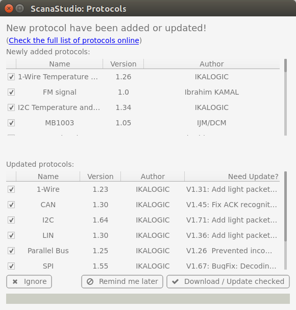
The first time I launched the program I was prompted to update the protocols, which are written in JavaScript, and open souce with the code on Github.
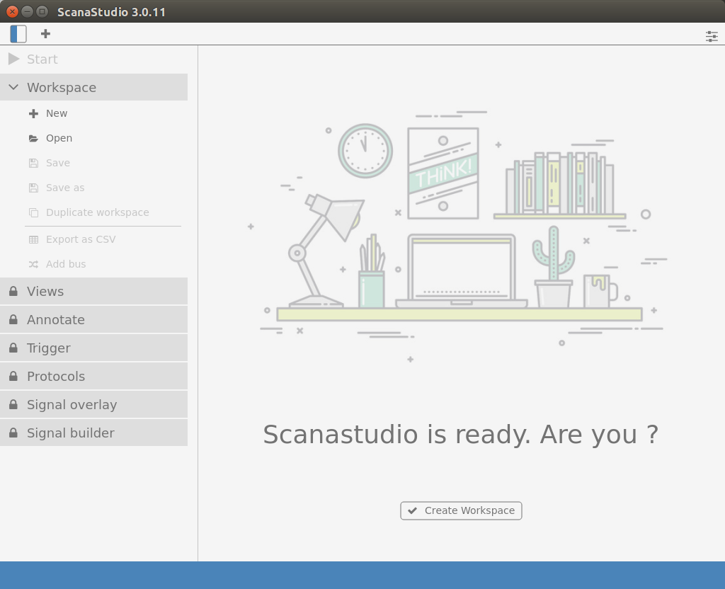
Click on Download / Update checked button to have the latest protocols loaded into the program. After that, you should get to the main user interface.
I clicked to create a new workspace, which showed several ScanaQuad “demo” devices, but no way to connect to the actual hardware.
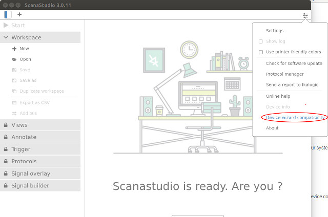
However, after searching in the knowledge base, I found out I may have to use the Device wizard compatibility, which can be accessed from the top right icon, and will start a 5-step wizard asking you to disconnect any SUB serial device – including your ScanaQuad -,and reconnect the ScanQuad.
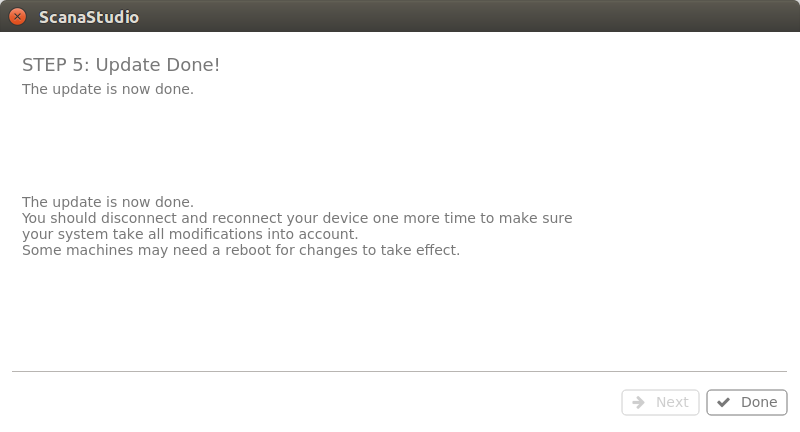 Everything is pretty self-explanatory, and this step may be needed in either Linux or Mac OS X, but not in Windows. You should now see your ScanaQuad USB logic analyzer listed when creating a new workspace, possibly after a reboot (but not needed here).
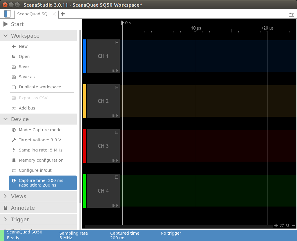
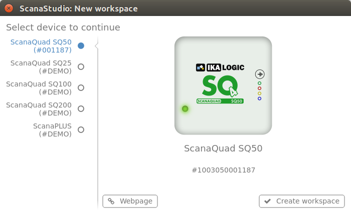 I selected ScanaQuad SQ50, and clicked on Create workspace button. The very first time, I had to wait as ScanaStudio updated ScanaQuad firmware, which took around a minute. Your workspace should now be shown with the 4-channel used by the tool and some default configuration.
Since last week I reviewed tinyLIDAR, a board based on STM32L0 MCU + VL53L0X ToF sensor that returns the distance from obstacles up to 2 meters away, and that interfaces with the host processor over I2C, I decided to monitor I2C signals with the device.
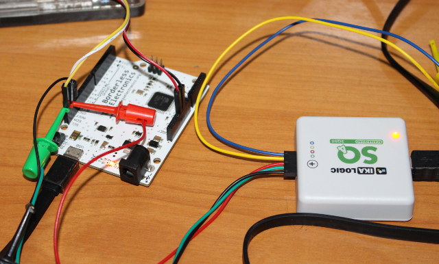
I connected the black probe to a ground pin, the green probe to SCL, and the red probe to SDA as shown above.
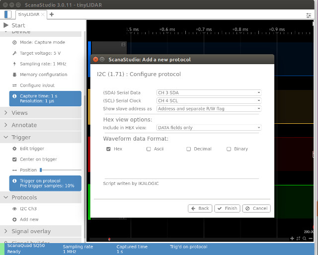
In ScanaStudio, I set sampling rate to 1 MHz, voltage to 5V, clicked on Add new in the Protocols section, selected I2C from the list, assigned CH 3 (Red) to SDA and CH 4 (Green) to SDL, and clicked Finish. Finally, I also set a trigger to start capture whenever I2C signals are detected.
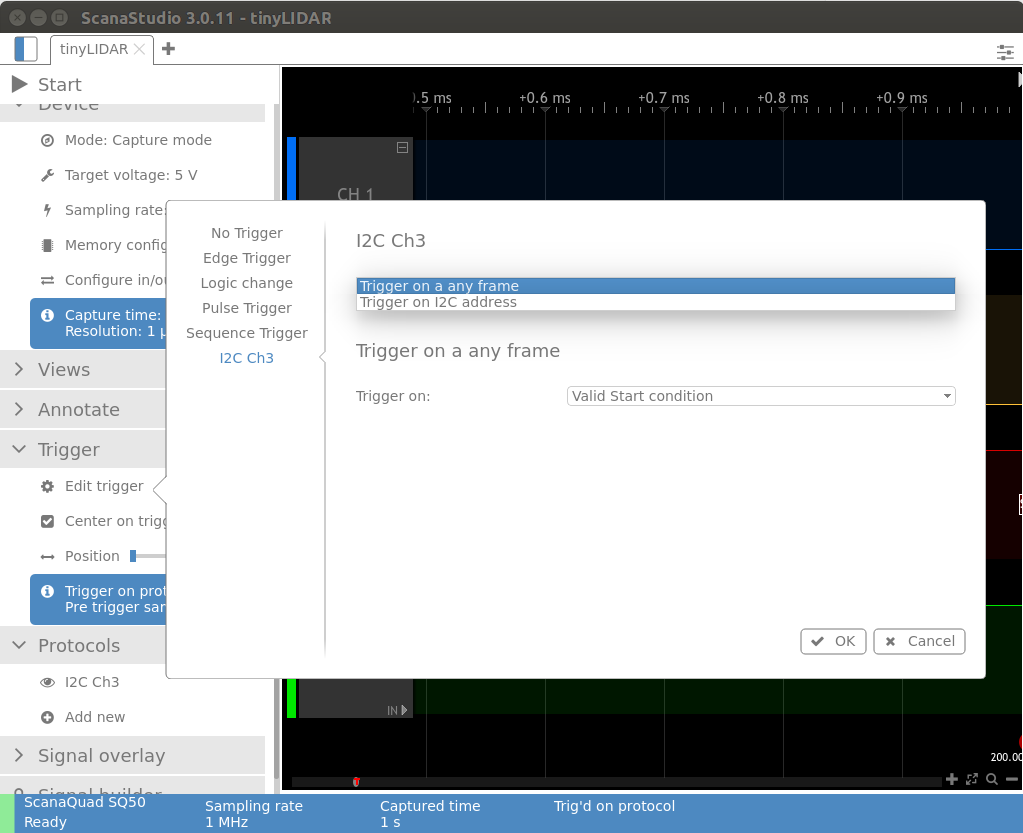
Now we can click Start at the top right of the interface to make the program wait for the trigger. Going the “Arduino GUI terminal” for tinyLIDAR board, I press enter to read distance (2 byte) from I2C device with address 0x10.
|
1 |
[default] Command 'D' to 0x10 Distance = 120mm |
The command ‘D’ should be 0x44 according the ASCII table, and the distance returned is 120 mm.
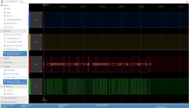
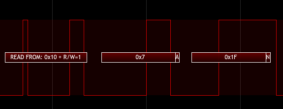
Right after pressing enter, ScanaStudio captured the SDA and SCL signal and decoded data with a write and a read command as expected:
- Write 0x10 with 0x88
- Read 0x10 with 0x00 and 0x78
I would have expected 0x44 (‘D) in the write command, but for some reasons I have not looked into, the command is shifted by one bit. The read data is however fully as expected as 0x78 converted to 120 mm.
I then made the sensor to face the ceiling in order to get a longer distance and use the two fields.
|
1 |
[default] Command 'D' to 0x10 Distance = 1823mm |
The terminal reports 1823mm, and the I2C capture show 0x071F distance which indeed converts to 1823 mm. So all good here.
If you’re interested in the other supported protocols, you could check out the aforelinked Github repository, and the screenshot below (correct as of February 5, 2018).
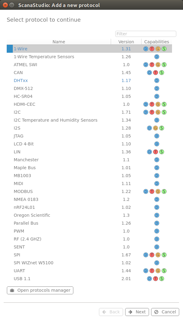 More protocols may eventually be supported, or you could roll your own JavaScript decoder if needed.
ScanaQuad SQ50 Signal Generator in Ubuntu 16.04
ScanaQuad also works as a signal generator using the same ScanaStudio program. Mixed mode is supported too, with two inputs for the logic analyzer, and two outputs for the signal generator. I expected to be able to easily generate sine waves, square waves, and sawtooth waves, but one you switch to Generator mode, the only two options in the Signal builder section are:
- Square signal wizard up between 1 Hz and 12.5 MHz (min/max values depend on sampling rate) with with duty cycle slider.
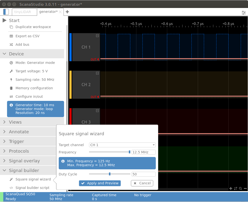
- Signal builder script
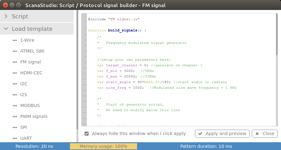
The latter has template with all sort of signal include 1-wire, HDMI-CEC, MODBUS, PWM, SPI, and so on. It also mean you should be able to create seesaw and sine waves, but you may have to work (i.e. write some JavaScript code) for it.
Instead of feeding back the signal to the device in mixed mode, I used SQ50 to generate signals, and WS200 probe for measurement.
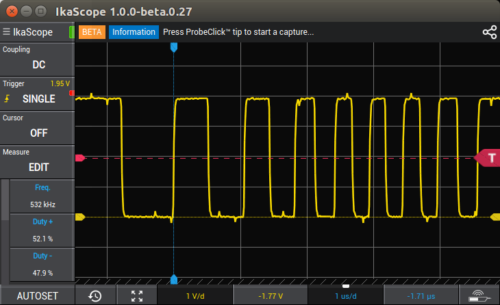
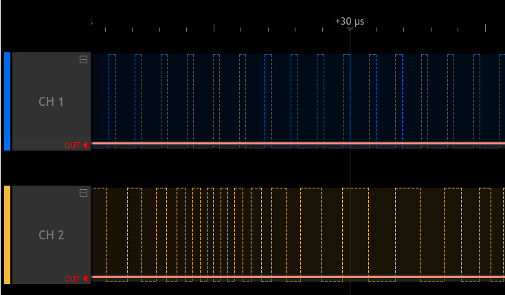
- CH1 generating 12.5 MHz square wave with 25% duty cycle
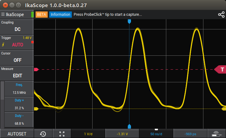
Not what I would call a neat square signal, and the 25% duty signal is not quite right either due to the distorsion.
- Let’s lower the frequency to 1 MHz with the same duty cycle.
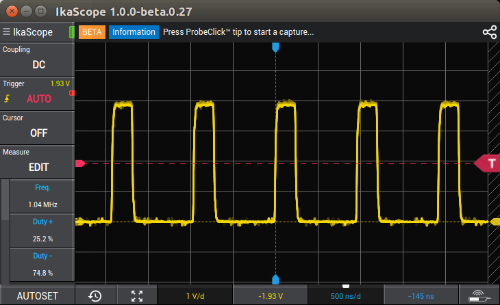
That’s more like it, although there’s still some noise.
-
- CH2 generating FM signals
 The waveform looks fairly good, and matches the one defined in ScanaStudio.
I’d like to thank Ikalogic for the opportunity to test their measurement devices. IkaScope WS200 oscilloscope sells for 299 Euros exc. VAT, while ScanaQuad SQ50 goes for 89 Euros exc. VAT, and other USB LA+SG models with better specifications such as SQ200 go for up to 149 Euros.

Jean-Luc started CNX Software in 2010 as a part-time endeavor, before quitting his job as a software engineering manager, and starting to write daily news, and reviews full time later in 2011.
Support CNX Software! Donate via cryptocurrencies, become a Patron on Patreon, or purchase goods on Amazon or Aliexpress




Not using the ground-clip ?
With a battery powered scope??
Your signals should have strange disturtions and in lower frequency range you should always see 50 Hz.
It could even explain why you’re getting a siniod shaped signal out of a digital IC 😉
@Tkroenert
I used the ground clip for all measurements.
I can only see such issue when measuring the signal generator signal with the oscilloscope.
300€ for a single probe oscilloscope with so low specs? And it requires and external computer/smartphone?
A little more and you’ll buy a 4 channel standalone Rigol scope with much better specs and functions!
At half the price, maybe it could be interesting.
I bought their ScanaLogic-2 Pro signal generator, which in theory could record analog signals and later output the playback. Not sure if it was the software or hardware/firmware, it never quite worked right.
Either way, it was dropped.. and recently, their forum with years of questions/answers was also wiped clean.
Personally, I would be hesitant purchasing from Ikalogic again.
@ben Hello Ben, I totally understand your frustration. Tough choices had to be made to offer better products and more importantly better support. loosing the old forum was a painful decision, but we had no other choice. We continue though to offer full support for our clients and customers, even for discontinued products, of course. I am sorry there was a misunderstanding about Scanalogic-2 recording analog signals, but Scanalogic-2 is a logic analyzer, and it was never meant to work with anything else but logic signals. Also, if your device have issue, please do contact our customer support, we’ll gladly… Read more »
Someone : 300€ for a single probe oscilloscope with so low specs? And it requires and external computer/smartphone? A little more and you’ll buy a 4 channel standalone Rigol scope with much better specs and functions! At half the price, maybe it could be interesting. I get your point, but it is complicated to compare both products. IkaScope WS200 was designed not to be “low cost”, but to be functional and ergonomic. Plus, the software supporting the product on all platforms is really pleasant to use. This matters a lot on the long run. Some users do need to have… Read more »
I do think that the long wire of the logic analyzer is adding a lot of inductance..
They have a 50 Euros discount coupon ECE2018 for WS200 probe.
15% discount with coupon code “15FORBIGFANS” for bundle WS200 + ScanaQuad SQ200.